Porter-Cable 557 Instruction Manual
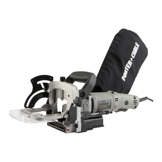
Double insulated plate joiner
Hide thumbs
Also See for 557:
- Instruction manual (23 pages) ,
- Instruction manual (18 pages) ,
- Instruction manual (64 pages)
Table of Contents
Advertisement
Quick Links
900016 - 10-31-01.qxd
Instruction
manual
To learn more about Porter-Cable
visit our website at:
http://www.porter-cable.com
Copyright © 2001 Porter-Cable Corporation
2/12/02
2:37 PM
Page 1
Double Insulated
Plate Joiner
Please make certain that the person who is
to use this equipment carefully reads and
understands these instructions before
starting operations.
The Model and Serial No. plate is located on the main
housing of the tool. Record these numbers in the
spaces below and retain for future reference.
Model No. ______________________________________
Type ___________________________________________
Serial No. _______________________________________
ESPAÑOL: PÁGINA 19
FRANÇAISE : PAGE 39
MODEL
557
IMPORTANT
Part No. 900016 - 10-31-01
Advertisement
Table of Contents

Related Manuals for Porter-Cable 557


Summary of Contents for Porter-Cable 557
- Page 1 Double Insulated manual Plate Joiner MODEL IMPORTANT Please make certain that the person who is To learn more about Porter-Cable to use this equipment carefully reads and visit our website at: understands these instructions before http://www.porter-cable.com starting operations. The Model and Serial No. plate is located on the main housing of the tool.
-
Page 2: General Safety Rules
900016 - 10-31-01.qxd 2/12/02 2:37 PM Page 2 WARNING: SOME DUST CREATED BY POWER SANDING, SAWING, GRINDING, DRILLING, AND OTHER CONSTRUCTION ACTIVITIES contains chemicals known to cause cancer, birth defects or other reproductive harm. Some examples of these chemicals are: ·... -
Page 3: Personal Safety
900016 - 10-31-01.qxd 2/12/02 2:37 PM Page 3 PERSONAL SAFETY Stay alert, watch what you are doing, and use common sense when operating a power tool. Do not use tool while tired or under the influence of drugs, alcohol, or medication. A moment of inattention while operating power tools may result in serious personal injury. -
Page 4: Specific Safety Rules And Symbols
WARNING: There are certain applications for which this tool was designed. Porter-Cable strongly recommends that this tool NOT be modified and/or used for any application other than for which it was designed. If you have any questions relative to its application DO NOT use the tool until you have written Porter-Cable and we have advised you. -
Page 5: Replacement Parts
When servicing use only identical replacement parts. MOTOR Many Porter-Cable tools will operate on either D.C., or single phase 25 to 60 cycle A.C. current and voltage within plus or minus 5 percent of that shown on the specification plate on the tool. Several models, however, are designed for A.C. -
Page 6: Functional Description
FUNCTIONAL DESCRIPTION FOREWORD Model 557 is designed to cut the grooves required for Porter-Cable biscuit sizes “FF”, “0”, “10”, and “20”. Adjustments are also provided which allow the tool to cut grooves for the following plate joiner accessories sold by other manufacturers: #6 biscuits, Duplex accessories, and Simplex accessories. -
Page 7: Fine Adjustment
10 For “10” size accessories Fig. 2 20 For “20” size accessories MAX For “6” size accessories, provides maximum depth of cut with 4" blade FF For Porter-Cable “FF” biscuits For “Duplex” accessories For “Simplex” accessories FINE ADJUSTMENT (Depth of Groove) The “quick set”... - Page 8 Fig. 4 Fig. 5 ADJUSTABLE FENCE Model 557 is equipped with an integral, adjustable fence which: • Provides micro height adjustment, distance scale includes indexes to top of cut, to center of cut, and to bottom of cut. • Tilts 0° through 135°, with an adjustable stop at 90°.
- Page 9 BLADES (2" and 4") Model 557 is shipped with a 4" diameter blade installed. This blade is used for all operations except for the “FF” biscuit. The “FF” biscuit requires that the 2" blade (furnished with the tool), be installed as follows: CAUTION: Disconnect tool from power source.
- Page 10 900016 - 10-31-01.qxd 2/12/02 2:38 PM Page 10 Fig. 11 Fig. 10 Continue to hold spindle lock button while using the hex wrench (furnished with tool), to tighten blade retaining bolt securely, (by rotating clockwise). Rotate the “quick set” depth adjusting turret (A) Fig. 12, to the “FF” position.
- Page 11 900016 - 10-31-01.qxd 2/12/02 2:38 PM Page 11 11. Reposition blade cover plate to tool, and secure in place with the four retaining screws (removed in step 1). WARNING: Do not operate tool without blade cover installed. ASSEMBLY ALIGNMENT PLATE (For Narrow Stock) When joining narrow material, it will be necessary to install the alignment plate (A) Fig.
-
Page 12: Operation
“DUPLEX” HINGES The 557 can be used to make the mortises required for installing “duplex” hinges. To accomplish this, you must make a spacer and attach it to the 557 fence. The spacer can be made of scrap " thick wood. Cut the spacer to approximately 3 "... - Page 13 900016 - 10-31-01.qxd 2/12/02 2:38 PM Page 13 CORNER JOINT SURFACE JOINT PRACTICE CUTS BUTT After each set-up JOINT adjustment to the tool, it is recommended you make several practice cuts in scrap material to verify desired operation. CORNER JOINTS Layout groove positions Fig.
- Page 14 900016 - 10-31-01.qxd 2/12/02 2:38 PM Page 14 Hold tool firmly as shown in Fig. 21, squeeze trigger switch to start tool. At a slow, steady pace, push tool forward in base as far as depth stop allows. Release trigger switch to stop tool and remove tool from work.
-
Page 15: Butt Joints
900016 - 10-31-01.qxd 2/12/02 2:38 PM Page 15 At a slow, steady pace, push tool forward in base as far as depth stop allows. Release trigger switch to stop tool and remove tool from work. 10. Repeat steps 5 through 8 until all the grooves in workpiece “A” are completed. -
Page 16: Maintenance
900016 - 10-31-01.qxd 2/12/02 2:39 PM Page 16 Fig. 29 Fig. 28 Hold tool firmly as shown in Fig. 28, and squeeze trigger switch to start tool. At a slow, steady pace, push tool forward in base as far as depth stop allows. -
Page 17: Service And Repairs
(model number, type, serial number, etc.). ACCESSORIES A complete line of accessories is available from your Porter-Cable • Delta Supplier, Porter-Cable • Delta Factory Service Centers, and Porter-Cable Authorized Service Stations. Please visit our Web Site for a catalog or for the name of your nearest www.porter-cable.com... - Page 18 PORTER-CABLE LIMITED ONE YEAR WARRANTY Porter-Cable warrants its Professional Power Tools for a period of one year from the date of original purchase. We will repair or replace at our option, any part or parts of the product and accessories covered under this warranty which, after examination, proves to be defective in workmanship or material during the warranty period.
- Page 19 Pour obtenir des pièces et accessoires pour les produits Porter-Cable • Delta, s’adresser à tout distributeur Porter- Cable • Delta, centre de service agréé ou centre de service d’usine Porter-Cable • Delta. Si vous n’avez accès à aucun de ces centres, appeler le 888-848-5175 et on vous dirigera vers le centre de service d’usine Porter-Cable •...