
Related Manuals for Master Lift Conveyor


Summary of Contents for Master Lift Conveyor
- Page 1 CONVEYORS Cinta de elevación Lift Conveyor Manual de uso y mantenimiento Instructions for use and maintenance...
-
Page 3: Table Of Contents
Contenido 1. Cinta de elevación 5. Indicaciones básicas de seguridad 2. Indicaciones generales 5.1. Símbolos de seguridad 2.1. Objetivo del manual 5.2. Seguridad para el operario 2.2. Dónde dejar el manual 5.3. Quién puede utilizar la cinta de elevación 3. Garantía 5.4. -
Page 4: Cinta De Elevación
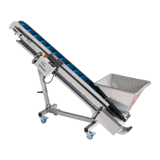
La cinta de elevación es un transportador de banda que permite alimentar de forma constante diferentes máquinas como la clasificadora de flores Master Sorter 500, la peladora Master Tumbler 500 o la peladora Master Tumbler 500 Medical. Su velocidad es ajustable según las necesidades del producto a tratar. - Page 5 Solo un trabajador cualificado por Master Products Inoxidable SL puede desmantelar, reparar e instalar nuevas piezas. En caso de que el producto esté en periodo de garantía, solo un trabajador de Master Products Inoxidable, SL puede realizar acciones sobre estos sin perder la garantía.
-
Page 6: Exclusiones De Responsabilidad
De no ser así, contactar con el servicio técnico de Master Products Inoxidable, S.L o su distribuidor. - Page 7 ¡IMPORTANTE! Accionar los frenos de las cuatro ruedas del soporte para evitar el desplazamiento involuntario del equipo durante su montaje. Debido al transporte y para evitar daños en los componentes, la cinta transportadora y el soporte sé entre- gan pre montados como se muestra en la siguiente imagen. En primer lugar, es necesario desatornillar y retirar con ayuda de una llave Allen n.º...
- Page 8 Con ayuda de otra persona, bascular y sujetar la cinta transportadora hasta alcanzar la posición mostrada en la siguiente imagen aproximadamente. Posteriormente, bascular también el brazo telescópico y aflojar la manecilla habilitada en él para poder deslizar el tubo hasta alcanzar la longitud deseada. Apretar la manecilla para fijar su posición.
- Page 9 Colocar la bandeja inferior entrándola, en primer lugar, por el lateral de la cinta transportadora como se muestra en la siguiente imagen y desplazándola, a continuación, hacia abajo hasta encajarla en los tubos del so- porte. Conectar el extremo del cable de alimentación al conector hembra de la caja eléctrica. Finalmente, conectar un extremo del cable de alimentación suministrado al conector hembra presente en la caja eléctrica y el otro extremo a la corriente eléctrica.
-
Page 10: Controles A Realizar Antes De Trabajar
En caso de existir alguna duda sobre aspectos y/o problemas no cubiertos en este manual, no dudar en comuni- carse con Master Products Inoxidable, S.L para solicitar asistencia técnica. Un mantenimiento de rutina o preventivo constituye una práctica necesaria de seguridad. Se lleva a cabo solamen- te con unos pasos básicos y ayudará, a garantizar una vida útil, larga y confiable del equipo adquirido. - Page 11 Desconectar el extremo del cable de alimentación, representado en color rojo en la siguiente imagen, de la caja eléctrica. Retirar la caja eléctrica como se muestra en la siguiente imagen. Retirar la bandeja inferior, levantándola levemente en primer lugar y seguidamente desplazándola hacía arribar para poderla extraer por el lateral como se muestra en la siguiente imagen.
- Page 12 Retirar la tolva de alimentación, desplazándola en primer lugar suavemente en la dirección mostrada en la si- guiente imagen, y levantándola a continuación. Aflojar los pomos de ambos lados y tirar suavemente hacia arriba, cada uno de los dos resguardos laterales, para desencajarlos y retirarlos como se muestra en la siguiente imagen.
- Page 13 Para lograr disolver la suciedad de la mejor manera, mantenga la temperatura del agua entre 32 °C-57 °C. Final- mente, para completar la limpieza, pulverizar el equipo y sus componentes con Master Clean. No utilizar deter- gentes ni otros productos de limpieza no especificados por el fabricante. Dejar actuar Master Clean durante varios segundos y a continuación, retirarlo solo con ayuda de papel.
- Page 14 Bascular el cabezal tensor, hasta la posición de tensando, y comprobar que los seguros del cabezal tensor que- dan bien posicionados. Posicionar y encajar los dos resguardos laterales como se muestra en la siguiente imagen. Finalmente, atornillar los dos pomos de ambos lados para asegurar la posición. Posicionar y encajar la tolva de alimentación encima de los dos resguardos laterales ayudándose para ello de las cuatro ranuras con perfil de bombín presentes en la base de la tolva y las cuatro cabezas de los tornillos Allen de los resguardos laterales.
- Page 15 Posicionar y encajar la bandeja inferior en el soporte de la banda transportadora como se muestra en la siguien- te imagen. Entrarla en primer lugar por el lateral y a continuación, desplazándola hacia abajo y dejándola encajada en los tubos del soporte. Montar la caja eléctrica encajándola en las ranuras del cuerpo principal de la banda transportadora.
-
Page 16: Desmontaje Y Desmantelamiento
Finalmente, conectar un extremo del cable de alimentación suministrado al conector de la caja eléctrica y el otro extremo a la corriente eléctrica. ¡IMPORTANTE! Asegurarse que el cableado eléctrico queda perfectamente colocado, sin formar bucles que puedan hacer tropezar los usuarios. 12. - Page 17 15. Datos generales Cinta de elevación Master Modelo 90 W Potencia CMP-839-00-B Manual España País MASTER PRODUCTS INOXIDABLE, S.L. Nombre de la empresa Veïnat de la Banyeta nova, 10 Dirección Palol de Revardit Localidad Teléfono (+34) 972 299 355 Email info@masterproducts.es...
- Page 18 www.masterproducts.es...
- Page 19 5.1. Security symbols 2.1. Aim of the manual 5.2. User safety 2.2. Where to keep the manual 5.3. Who can use the lift conveyor 3. Warranty 5.4. Repairing the lift conveyor 4. Contents of the box 5.5. How to stop the lift conveyor 6.
-
Page 20: Lift Conveyor
3. Warranty Master Products offers a 2 years warranty on any defective part on this machine, as long as the defect is not due to misuse and/or lack of maintenance. For the warranty, it is essential to present the purchase invoice and get in contact with the manufacturer info@masterproducts.es. - Page 21 Only a qualified worker of Master Products Inoxidable SL may dismantle, repair and install new parts in the machi- ne. In the event that the product is in the warranty period, it must be dismantled by Master Products Inoxidable SL staff without voiding the warranty.
-
Page 22: Disclaimers
9. Placement The Lift conveyor must be placed on a flat surface, without irregularities on the ground, ensuring stability and a good working position. It is only suitable for indoor use and under no circumstances should the electrical part be exposed to water. - Page 23 ¡IMPORTANT! Apply the brakes on the four wheels of the support to prevent unintentional movement of the equipment during assembly. Due to transport and in order to avoid damage to the components, the conveyor belt and support are deli- vered pre-assembled, as shown in the following image. First of all, unscrew and remove the two DIN 7380 M8 screws and the two stop washers, shown in red in the following image, using an Allen key no.
- Page 24 With the help of another person, tilt and hold the conveyor belt until it reaches the position shown in the fo- llowing image, approximately. Subsequently, also tilt the telescopic arm and loosen the handle on it so that the tube can be slid to the desired length.
- Page 25 Place the lower tray by first inserting it into the side of the conveyor belt as shown in the following image and then sliding it downwards until it is fitted into the tubes of the support. Connect the end of the power cable to the socket connector on the electrical box. Finally, connect one end of the power cord supplied to the socket on the electrical box and the other end to the mains power supply.
-
Page 26: Checks To Be Carried Out Before Connecting
Failure to follow the instructions and safety precautions could cause serious injury to persons and damage to the equipment. If there is any question about issues or problems not covered by this manual, do not hesitate to contact Master Products Inoxidable, S.L. to request technical assistance. - Page 27 Disconnect the end of the power cable, shown in red in the following image, from the electrical box. Remove the electrical box as shown in the image below. Remove the lower tray by first lifting it slightly and then moving it upwards so that it can be pulled out from the side as shown in the following image.
- Page 28 Remove the feed hopper by first moving it gently in the direction shown in the image below, and then lifting it up. Loosen the knobs on both sides and gently pull upwards, each of the two side guards, to undo and remove them as shown in the following image.
- Page 29 Master Clean. Do not use detergents or other cleaning products not specified by the manufacturer. Let Master Clean act for several seconds and then remove it with the help of paper. 11.3. Assembly the equipment Once the equipment and its components have been cleaned, complete the assembly of the conveyor belt following the instructions below.
- Page 30 Tilt the tensioning head to the tensioning position and check that the tensioning headlocks are correctly positio- ned. Place and fit the two side guards as shown in the following image. Finally, screw up the two knobs on both sides to secure the position.
- Page 31 Position and fit the lower tray on the conveyor belt support as shown in the following image. First insert it from the side and then slide it downwards and fit it into the tubes of the support. Assemble the electrical box by fitting it into the slots in the main body of the conveyor belt. Connect the end of the power cable, shown in red in the following image, to the connector on the electrical box.
-
Page 32: Disassembly And Dismantling
14. Residuals risks The improper use of the machine can lead to: REASON DANGER REMAINING RISKS PRECAUTION Not tightening screws The lift conveyor can be Crushing and entrapment Secure and tighten screws correctly disassembled of the operator firmly Not placing correctly,... - Page 33 15. GENERAL DATA Master Lift Conveyor Model 90 W Power CMP-839-00-B Manual Spain Country MASTER PRODUCTS INOXIDABLE, S.L. Name of the company Veïnat de la Banyeta nova, 10 Address Palol de Revardit Location Telephone (+34) 972 299 355 Email info@masterproducts.es www.masterproducts.es...
- Page 34 Email: info@masterproducts.es N.I.F: B55310817 Declara bajo su única responsabilidad que la máquina Cinta de elevación Master, con Nº de serie: Declares under its sole responsibility that the machine Master Lift Conveyor, with serial Nº. : se encuentra en conformidad con la Directiva de Máquinas 2006/42/CE.