
Related Manuals for Invacare Esprit Action


Summary of Contents for Invacare Esprit Action
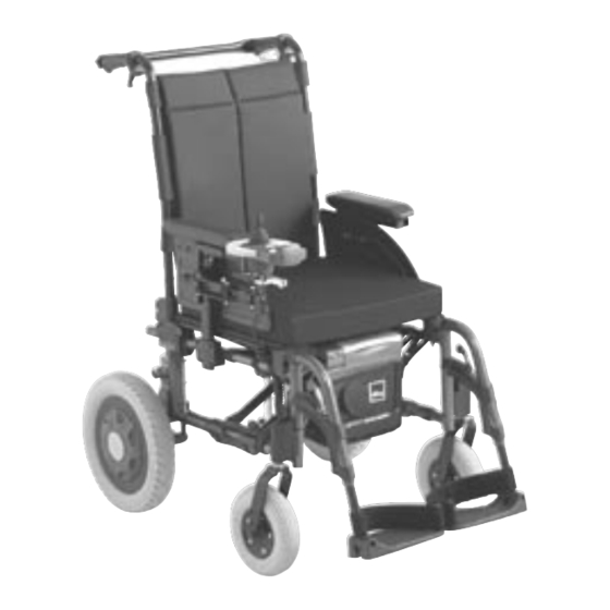
- Page 1 ® Invacare Esprit Action S E R V I C E M A N U A L ( M A I N T E N A N C E A N D A D J U S T M E N T ) The procedures in this manual MUST be performed by a qualified technician.
-
Page 2: Table Of Contents
TABLE OF CONTENTS T A B L E O F C O N T E N T S SECTION 1—TROUBLESHOOTING A N D M A I N T E N A N C E ......... 4 General information ......................4 Troubleshooting. - Page 3 TABLE OF CONTENTS SECTION 6—SEAT-TO-FLOOR HEIGHT .................. 29 Measuring Seat-to-Floor Height ..................29 Changing Seat-to-Floor Height ................... 30 SECTION 7—OPTIONS ......................31 Installing/Adjusting Headrest ....................31 SECTION 8—ANTI-TIPPERS ....................32 Installing/Adjusting Anti-Tippers ..................32 SECTION 9—PERIODIC MAINTENANCE GUIDELINES ............33 Initially ..........................
-
Page 4: Section 1-Troubleshooting A N D M A I N T E N A N C E
For pre-sales information and user manual related to this wheelchair, please consult the www.invacare.eu.com website. Esprit Action Junior specific options: Refer to Action³ Junior Service Manual for specific options (adjustable cross brace, back- brace, headrest, …) dedicated to the Junior version. -
Page 5: Maintenance Guidelines
SECTION 1— MAINTENANCE GUIDELINES C A U T I O N It is compulsary to use original Invacare spare parts which you can obtain from any Invacare subsidiaries. A list of spare parts is available at www.invacare.eu.com W A R N I N G After ANY adjustments, repair or service and before use, make sure all attaching hardware is tightened securely - otherwise injury or damage may occur. -
Page 6: Tightened Torques
SECTION 1— MAINTENANCE GUIDELINES & STABILITY WARNING 5. The wheels, castors and tyres should be checked periodically for cracks and wear; and should be replaced when necessary. 6. Periodically check castor wheel bearings to make sure they are clean and free from ®... -
Page 7: Section 2-Front Hangers
SECTION 2—FRONT HANGERS S E C T I O N 2 — F R O N T H A N G E R S W A R N I N G After ANY adjustments, repair or service and before use, make sure all attaching hardware is tightened securely - otherwise injury or damage may occur. -
Page 8: Replacing Heel Strap
SECTION 2—FRONT HANGERS Replacing Heel Strap NOTE: For this procedure, refer to FIGURE 2.2. 1. Remove the locking screw that secure the footrest tube to the footrest support. 2. Remove the lower footrest assembly. 3. Remove the mounting screw, strap pin that secure the heel strap to the footplate. -
Page 9: Installing Angle Adjustable Footplate
SECTION 2—FRONT HANGERS Installing Angle Adjustable Footplate NOTE: For this procedure, refer to FIGURE 2.4. NOTE: This procedure is for individual Angle and Depth Adjustable Footrests standard version (1) and new version (2) only. 1. Position the angle adjustable footplate on the footrest support tube at the desired height. -
Page 10: Adjusting The Footplate Height
SECTION 2—FRONT HANGERS 2. Reposition footplate to desired height, securely tighten locking screw 3. If necessary, repeat STEPS 1 2 to adjust remaining footplate height. Adjusting Calf pad Height 1. Loosen the locking button that secure the calf pad bracket to the elevating legrest assembly. -
Page 11: Section 3-Armrests
SECTION 3—ARMRESTS S E C T I O N 3 — A R M R E S T S W A R N I N G After ANY adjustments, repair or service and BEFORE use, make sure all attaching hardware is tightened securely - otherwise injury or damage may occur. To adjust the armrest, refer to dedicated paragraphs in user manual. - Page 12 SECTION 3—ARMRESTS 2. Move the side protection upwards or downwards until you reach the desired height. 3. Tighten the 2 screws of the side protect (0,7–1,2 Nm) with 4 mm Allen key or Pozidriv screwdriver. 4. Perform the setting on both sides. FIGURE 3.1 Removable and Multi-adjustable Armrest Adjusting the Depth and Height of the Control Unit...
-
Page 13: Replacing Armrest Arm Pad
SECTION 3—ARMRESTS Replacing Armrest Arm pad NOTE: For this procedure, refer to FIGURE 3.3. 1. Remove the mounting screws (M5) that secure the arm pad to the armrest assembly. 2. Replace arm pad and securely tighten with the existing mounting screws (M5). 3. -
Page 14: Section 4-Seat/Back
SECTION 4—SEAT/BACK S E C T I O N 4 — S E A T / B A C K W A R N I N G The seat height, seat depth, back angle, seating system, size/position of the rear wheels, size/position of the front castors, seating options (e.g. -
Page 15: Removing/Installing Standard Back Upholstery
SECTION 4—SEAT/BACK 1. Fold the wheelchair. 2. Remove the mounting screw (Torx) that secures the seat upholstery to the front and back seat rails. 3. Remove the end caps from the front of the seat rails. 4. Slide the seat upholstery out of the seat rails. FIGURE 4.2 Removing/Installing Seat Upholstery Removing/Installing Standard Back Upholstery NOTE: For this procedure, refer to FIGURE 4.3. -
Page 16: Contour (Adjustable) Back-Upholstery
SECTION 4—SEAT/BACK Contour (adjustable) Back-Upholstery Contour (adjustable) Tension Strips The adjuster strips can be adjusted at various levels of tension to accommodate individual end users. In a typical scenario, the bottom two strips can be adjusted tightly to support and/or assist the extensor muscles. Installing/Replacing Adjustable Back-Upholstery NOTE: For this procedure, refer to FIGURE 4.4, next page. - Page 17 SECTION 4—SEAT/BACK 4. Slide each section (anchor loop/adjuster strap) of the new adjustable back-upholstery with the grommet hole facing the rear of the wheelchair. 5. Secure new adjustable back-upholstery to the back-canes with the two mounting screws and washers. W A R N I N G Ensure that the wheelchair is fully opened, the back brace is fitted, and the seat rails properly located.
-
Page 18: Adjusting The Height Adjustable Back
SECTION 4—SEAT/BACK Adjusting the Height Adjustable Back NOTE: For this procedure, refer to FIGURE 4.5. 1. Loosen, but DO NOT remove, the height adjustment knobs. 2. Reposition the back canes to the desired height. NOTE: Both back canes should be adjusted to the same height. NOTE: DO NOT raise push handles to maximum height when tilting the chair. -
Page 19: Removing/Installing Different Type Of Backrests
SECTION 4—SEAT/BACK DETAIL « A » Backrest Adjustable -15°/+15° DETAIL « B » Step Less Adjustment -15°/+15° Allen Key 5 mm FIGURE 4.6 Adjusting the Angle Adjustable Backrest Removing/Installing different type of Backrests NOTE: For this procedure, refer to FIGURE 4.7, next page Folding b a ckre s t NOTE: To Install the Fixed/Folding backrest, reverse this procedure from STEP 3 to 1. - Page 20 SECTION 4—SEAT/BACK Back-cane Mounting Backrest Cane Bracket Screws FIGURE 4.7 Fixed/Folding Backrests Removing/Installing different type of Backrests Re cline r bac k re st (Mech a nic a l a nd Gas strut v ersions) NOTE: For this procedure, refer to FIGURE 4.8. To Install the Recliner backrest;...
- Page 21 SECTION 4—SEAT/BACK Removing/Installing different type of Backrests Com fort backr es t (Mecha nical an d Ga s st rut v ers ions) NOTE: For this procedure, refer to FIGURE 4.9. To Install the Comfort backrest; reverse this procedure from STEP 1 to 3. 1.
-
Page 22: Removing/Installing/Adjusting The Back-Cane Bracket
SECTION 4—SEAT/BACK Removing/Installing the Back-cane Bracket NOTE: For this procedure, refer to FIGURE 4.10. NOTE: To install the back-cane bracket, reverse this procedure. 1. Remove the back canes. Refer to Removing Back-canes paragraph. 2. Pull up on the seat upholstery. 3. -
Page 23: Installing/Removing Seat Posture Belt
SECTION 4—SEAT/BACK Installing/Removing Seat Posture Belt NOTE: For this procedure, refer to FIGURE 4.11. 1. Remove seat cushion from wheelchair, if necessary. 2. Remove the mounting screw and locknut that secures the seat posture belt half to the back-cane bracket. 3. -
Page 24: Installing/Removing The Back-Brace
SECTION 4—SEAT/BACK Installing/Removing the Back-brace W A R N I N G If a back brace is already installed, you don’t have to re-install the back-cane inserts (for fixed back-canes only). After ANY adjustments, repair or service and before use, make sure all attaching hardware is fitted and tightened securely - otherwise injury or damage may occur. -
Page 25: Section 5-Rear Wheels/Front Casters
SECTION 5—REAR WHEELS/FRONT CASTORS SECTION 5—REAR WHEELS/FRONT CASTERS W A R N I N G The seat height, seat depth, back angle, seating system, position of the rear wheels, position of the front casters, seating options (e.g. headrest, back bag, …) as well as the user condition directly relate to the stability of the wheelchair. -
Page 26: Adjusting Rear Wheel Height
SECTION 5—REAR WHEELS/FRONT CASTORS Adjusting Rear Wheel Height NOTE: For this procedure, refer to FIGURE 5.2. 1. Remove the rear wheel. Refer to Removing/Fitting Rear Wheels paragraph. 2. Remove the locknut and washer that secures the axle bracket to the axle plate and the connector bracket (3 screws M4). -
Page 27: Adjusting Fork Rotation
SECTION 5—REAR WHEELS/FRONT CASTORS Adjusting Fork Rotation W A R N I N G Caster angle vertical axis MUST be at 90° +/- 1° from the ground, if not a flattering risk may occur. Both caster assemblies should be at the same angle. After ANY adjustments, before use, make sure all attaching hardware is tightened securely - otherwise injury or damage may occur. -
Page 28: Removing/Installing/Repositioning The Caster Assemblies
SECTION 5—REAR WHEELS/FRONT CASTORS Removing/Installing/Repositioning the Caster Assemblies NOTE: If replacing a front caster note the mounting position of the existing front caster for installation of the new front caster. NOTE: If repositioning front casters, refer to Changing Front Seat Floor Height paragraph to determine the front caster position needed for the required front seat-to floor height. -
Page 29: Section 6-Seat-To-Floor Height
SECTION 6—SEAT-TO-FLOOR HEIGHT SECTION 6—SEAT-TO-FLOOR HEIGHT W A R N I N G After ANY adjustments, repair or service and before use, make sure all attaching hardware is tightened securely - otherwise injury or damage may occur. Measuring Seat-to-Floor Height NOTE: For this procedure, refer to FIGURE 6.1. -
Page 30: Changing Seat-To-Floor Height
SECTION 6—SEAT-TO-FLOOR HEIGHT Changing Seat-to-Floor Height W A R N I N G The seat height, seat depth, back angle, seating system, position of the rear wheels, position of the front casters, seating options (e.g. headrest, back bag, …) as well as the user condition directly relate to the stability of the wheelchair. -
Page 31: Section 7-Options
SECTION 7—OPTIONS S E C T I O N 7 — O P T I O N S Installing/Adjusting Headrest W A R N I N G After ANY adjustments, repair or service and before use, make sure all attaching hardware is tightened securely - otherwise injury or damage may occur. -
Page 32: Section 8-Anti-Tippers
After ANY adjustments, repair or service and BEFORE use, make sure all attaching hardware is tightened securely - otherwise injury or damage may occur. Anti-tippers MUST be attached always. Invacare strongly recommends checking the fixation of the anti-tippers as they are an additional safeguard for the wheelchair user. -
Page 33: Section 9-Periodic Maintenance Guidelines
SECTION 9— PERIODIC MAINTENANCE GUIDELINES S E C T I O N 9 — P E R I O D I C M A I N T E N A N C E G U I D E L I N E S NOTE: Always clean the wheelchair before any inspection/adjustment. -
Page 34: Weekly/Monthly/Annually
SECTION 9—PERIODIC MAINTENANCE GUIDELINES Inspect/Adjust Weekly Wheelchair rolls straight (no excessive drag or pull to one side). Check and control the perfect fitting of the control unit on its armpad and armrest bracket and its absence of visual damage. Quick-release axles lock properly (see page 25). - Page 35 SECTION 9— PERIODIC MAINTENANCE GUIDELINES Inspect/Adjust every twelve months (2) Wheel brake pivot point are free of wear and looseness. Clean upholstery and armrests. Sealed bearings and axle nut tension are correct. Wheel/fork assembly has proper tension when caster is spun. Caster should come to a gradual stop. ...
- Page 36 Invacare France Operations SAS 60129701-A Route de St Roch 02-2021 37230 Fondettes, France...