Table of Contents
Advertisement
Quick Links
Download this manual
See also:
User Manual
Advertisement
Table of Contents

Related Manuals for Invacare Twister


Summary of Contents for Invacare Twister
- Page 1 Invacare® TWISTER TWISTER-JUNIOR SERVICE MANUAL These instructions contain information about: Troubleshooting Testing of Components Repair Edition: 10.2001...
- Page 2 • Information about operation or about general maintenance and care work should be taken from the corresponding wheelchair Operating Manual. • You can find information about complete replacement of the Twister Junior seating system in the Twister Junior assembly instructions.
- Page 3 Twister / Twister Junior Service Manual Notes on transport • If the wheelchair has to be shipped back to the manufacturer for major repairs, you should always use the original packaging for transport. • You should also include as accurate a fault description as possible.
-
Page 4: Table Of Contents
Twister/Twister Junior Service Manual Contents SAFETY AND ASSEMBLY INSTRUCTIONS Before any inspection or repair work During dismantling/reassembly Before operation / after completion of work: TOOL LIST LAYOUT OF MODULES, COMPONENTS AND DISPLAYS AND CONTROLS ELECTRONIC CONTROL COMPONENTS (ACS) General Module connection cables... - Page 5 Twister / Twister Junior Service Manual INSPECTION AND REPAIR WORK TO STANDARD SEATING SYSTEMS Armrests and side panels 9.1.1 Disassembly of armrests and side panels 9.1.2 Reassembly of armrests and side panels Standard legrests without angle-adjustable footplate 9.2.1 Disassembly of legrests 9.2.2...
- Page 6 Reassembly of the seat unit 11.10 Footplate for Twister Junior 11.10.1 Disassembly of the footplate 11.10.2 Reassembly of footplate 11.11 Legrest upper part for Twister Junior 11.11.1 Disassembly of legrest upper parts 11.11.2 Reassembly of legrest upper parts Page 6 Issued:21.01.02...
- Page 7 11.12.1 Disassembly of legrest attachments 11.12.2 Reassembly of legrest attachments 11.13 Chin control and switch joystick for Twister Junior 11.13.1 Disassembly of the chin control and switch joystick 11.13.2 Reassembly of the chin control and switch joystick TESTING AND REPAIR WORKS ON CHASSIS 12.1...
- Page 8 Twister/Twister Junior Service Manual 14.2 30 Ah battery unit. 14.2.1 Disassembly of battery unit 14.2.2 Reassembly of the battery unit 14.3 40 Ah battery unit. 14.3.1 Disassembly of battery unit 14.3.2 Reassembly of the battery unit 14.4 Charge batteries. 14.4.1 General 14.4.2...
- Page 9 Twister / Twister Junior Service Manual 16.4 Testing motor, magnetic brake and freewheel switch 16.4.1 Testing preparations / replacement of drive motors 16.4.2 Testing drive motor 16.4.3 Checking the magnetic brake 16.4.4 Checking the freewheel switch TESTING AND REPAIR WORK ON THE ACTUATOR MOTORS 17.1...
- Page 10 Twister/Twister Junior Service Manual TESTING THE DRIVING ELECTRONICS 19.1 Standard joystick box 19.1.1 Disassembly of the standard joystick box 19.1.2 Reassembly of the standard joystick box 19.1.3 Disassembly joystick box support tube and joystick box attachment 19.1.4 Reassembly joystick box stay bar and joystick box attachment 19.1.5...
- Page 11 Twister / Twister Junior Service Manual 20.2 Test procedure 20.2.1 Checking plugs and cables 20.2.2 Checking the sensors WHEELCHAIR PROGRAMMING 21.1 General 21.2 Programming on the PC 21.3 Programming with the programming device STORING THE WHEELCHAIR SAFETY AND ASSEMBLY INSTRUCTIONS...
- Page 12 Twister/Twister Junior Service Manual INSPECTION PLAN OPERATIONAL FAULTS General Fault causes ERROR MESSAGE AT JOYSTICK BOX Joystick box error codes INSPECTION AND REPAIR WORK TO STANDARD SEATING SYSTEMS Armrests and side panels 9.1.1 Disassembly of armrests and side panels 9.1.2...
- Page 13 General 11.2 Twister Junior headrest 11.2.1 Disassembly of headrest 11.2.2 Reassembly of headrest 11.3 Twister Junior backrest trunk supports 11.3.1 Disassembly of backrest trunk supports 11.3.2 Reassembly of backrest trunk supports 11.4 Electrical backrest adjustment, Twister Junior 11.4.1 Disassembly of actuator motor 11.4.2...
- Page 14 11.12.1 Disassembly of legrest attachments 11.12.2 Reassembly of legrest attachments 11.13 Chin control and switch joystick for Twister Junior 11.13.1 Disassembly of the chin control and switch joystick 11.13.2 Reassembly of the chin control and switch joystick TESTING AND REPAIR WORKS ON CHASSIS 12.1...
- Page 15 Twister / Twister Junior Service Manual 13.2.1 Converting the standard vehicle(without lifter) 13.2.2 Conversion of vehicle with lifter 13.3 Retrofitting the lifter module to current safety standards 13.3.1 Instructions for retrofitting the lifter module: 13.3.2 Final inspection TESTING AND REPAIR WORKS ON POWER SUPPLY 14.1...
- Page 16 17.5 Replacement of seat adjustment (with lifter module) 17.5.1 Disassembly (Twister) 17.5.2 Reassembly (Twister) 17.5.3 Disassembly (Twister Junior) 17.5.4 Reassembly (Twister Junior) 17.6 Replacing actuator of automatic seat back adjustment or support tube for manual seat back adjustment. 17.6.1 Disassembly 17.6.2...
- Page 17 Twister / Twister Junior Service Manual 18.4 Checking lighting modules or combined lighting / actuator module 18.4.1 Status display 18.4.2 Preparations for testing 18.4.3 Check the power supply from the power module to the lighting module 24V 12V, or to the lighting / actuator module 18.5...
- Page 18 Twister/Twister Junior Service Manual 19.6 Power module 19.6.1 Preparation 19.6.2 Removal of power module 19.6.3 Fitting the power module 19.7 Lighting and actuator module (Clam), lighting module and lighting module with voltage converter 19.7.1 General 19.7.2 Removal of module 19.7.3...
-
Page 19: Safety And Assembly Instructions
Twister / Twister Junior Service Manual 1 Safety and assembly instructions The safety instructions are intended as prevention of accidents at work and it is imperative that they are observed. Before any inspection or repair work • Read and observe this repair manual and the associated operating manual. -
Page 20: During Dismantling/Reassembly
Twister/Twister Junior Service Manual During dismantling/reassembly • Mark all current settings for the wheelchair (seat, armrests, backrest etc.), and the cable connecting plugs associated, before any removals. This makes reassembly easier. Caution: • Prop up the lifted wheelchair with appropriate supports before starting the disassembly or assembly. -
Page 21: Tool List
Twister / Twister Junior Service Manual 2 Tool list You will need a standard tool set with at least the following: • Open-end and ring spanner 6, 7, 8, 10, 11, 12, 13, 17, 19 (mm) • Allen key 2.5, 3, 4, 5, 6, 8, 10 (mm) •... -
Page 22: Layout Of Modules, Components And Displays And Controls
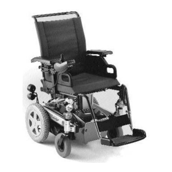
5. Side panel 6. Rear wheel 7. Battery 8. Front wheel 9. Footplates 10.Legrest Standard "Twister" configuration, 11. Standard joystick front wheel drive, without lighting with standard seat attachments, standard seat, standard backrest and 65°/73° legrests, without headrests. Page 22... - Page 23 Twister / Twister Junior Service Manual 1. . Recaro seat cushion 2. Side panel upholstery 3. . Recaro backrest upholstery 4. Armrest 5. Side panel 6. . Rear wheel, complete 7. Batteries 8. . Front wheel, complete 9. Footplates 10.Legrest, complete 11.Calf support...
- Page 24 7. Footplates 8. Legrest 9. Standard joystick 10. Calf support "Twister" configuration, front view with KAB seat, front wheel drive, manually adjustable backrest, manually adjustable seat tilting, height and tilt-adjustable footrests, standard joystick box, calf support without headrests. Page 24...
- Page 25 11. Front wheel 12. Battery 13. Footplate 14. Calf strap 15. Legrest "Twister Junior" configuration with Junior seating system, rear wheel drive, adjustable backrest, seat tilt, height and lean-adjustable footplate, standard joystick box, calf strap and headrest: Issued: 21.01.02 Page 25...
-
Page 26: Electronic Control Components (Acs)
Twister/Twister Junior Service Manual 4 Electronic control components (ACS) General The wheelchair's electronic control ACS (Action Control System) is composed of individual components (modules. According to type, the wheelchairs are equipped with different modules. ACS Control module : Module designation... - Page 27 DX - REM 41 / REM 41 S Chin control voltage converter for Recaro seat DX - ACC 1, or DC - DC converter Standard joystick box for Twister Junior (G - 80 - I) Chin control and switch joystick for Twister Junior...
-
Page 28: Module Connection Cables
Twister/Twister Junior Service Manual Module connection cables BUS cable The module connection cables are called BUS cables. They are designed as four- conductor cables. Two conductors serve the power supply and two the transfer of data. Cable allocation Power supply... - Page 29 The ACS is equipped with an error memory, which can be evaluated by means of a commercially available PC. Additionally required hardware and software can be obtained from INVACARE Deutschland GmbH under Item No.: P10 076. Issued: 21.01.02 Page 29...
-
Page 30: Module Composition
Twister/Twister Junior Service Manual 5 Module composition The composition of modules depends on the type of wheelchair. The basic equipment consists of the power module with its joystick box. The joystick box can be used for any available module that is not older than the original joystick box. -
Page 31: Wheelchair Fittings: With 24 V Lighting System, Without Actuators
Twister / Twister Junior Service Manual Wheelchair fittings: with 24 V lighting system, without actuators Module fittings: Cables: • • BUS cable to joystick Main module (power module) • • BUS cable from power Combined lighting + module to lighting... -
Page 32: Wheelchair Fittings: Without Lighting, With Actuators
Twister/Twister Junior Service Manual Wheelchair fittings: without lighting, with actuators Module fittings: Cables: • Main module (power • BUS cable to joystick module) • Combined lighting + • BUS cable from power actuator module module to lighting / actuator module •... -
Page 33: Wheelchair Fittings: With 24 V Lighting, With Actuators
Twister / Twister Junior Service Manual Wheelchair fittings: with 24 V lighting, with actuators Module fittings: Cables: • Main module • BUS cable to joystick box (power module) • BUS cable from power • Combined lighting module to lighting / actuator... -
Page 34: Wheelchair Fittings: With 12 V Lighting (Tüv Version), Without Actuators
Twister/Twister Junior Service Manual Wheelchair fittings: with 12 V lighting (TÜV Version), without actuators Module fittings: Cables: • Main module (power • BUS cable to joystick box module) • BUS cable from power • 12 module to lighting module V lighting module •... -
Page 35: Wheelchair Fittings: With 12 V Lighting (Tüv Version), With Actuators
Twister / Twister Junior Service Manual Wheelchair fittings: with 12 V lighting (TÜV Version), with actuators Module fittings: Cables: • Main module (power • BUS cable to joystick module) • Combined lighting + • BUS cable from power actuator module... -
Page 36: Wheelchair Fittings: With Electrically Adjustable Recaro Seat
Twister/Twister Junior Service Manual Wheelchair fittings: with electrically adjustable RECARO seat The RECARO seat basic equipment consists of the following components: Module fittings: Cables: • Main module (power • BUS cable to joystick module) • DC-DC Converter • Battery cable •... -
Page 37: Inspection Plan
Twister / Twister Junior Service Manual Inspection plan Component Check Remedy Chapter: • Check headrest shell and ⇒ Replace if damaged. Headrest upholstery. ⇒ Tighten screws, replace • Check headrest support components and screw connections. • Check headrest with ⇒ Replace if damaged. - Page 38 Twister/Twister Junior Service Manual Component Check Remedy Chapter: pressure spring. • Check seams and for 11.7 Twister Junior ⇒ Replace parts. damage. backrest unit • Check screw 11.7 ⇒ Tighten screws connections. ⇒ Replace seat if Check for function and Recaro seat damage.
- Page 39 Twister / Twister Junior Service Manual Component Check Remedy Chapter: • Check footplate. ⇒ Replace parts. 11.10 Twister Junior legrests • Check legrest upper ⇒ Replace parts. 11.11 parts. • Check legrest ⇒ Replace parts. 11.12 attachments • Check power supply.
- Page 40 Twister/Twister Junior Service Manual Component Check Remedy Chapter: • Check for damage to ⇒ Clean contacts, replace 14.2 Batteries batteries and case, batteries or battery boxes contact corrosion • Check contacts, terminals ⇒ Tighten, replace 14.3 • Check battery voltage ⇒...
-
Page 41: Operational Faults
Twister / Twister Junior Service Manual Operational faults General In the event of malfunctions to the drive mode, to the lighting system, the actuator motors or the power supply, please proceed as follows,: • First assess the fault causes described in Chapter .7.2 •... - Page 42 Twister/Twister Junior Service Manual Drive motor judders in drive mode Motor defective Replace motor Chapt.12.4 Manual for Programming Check programming wrong programming device or for PCD software One actuator motor does not react / reacts irregularly Motor or actuator module Check blink code at joystick Chapt.8...
- Page 43 Twister / Twister Junior Service Manual Lifter not functioning Check/replace Chapt.20 Cable / connector plug defective cable/connector plug Lifter module defective Replace lifter module Chapt. 13, Vehicle does not run at reduced speed with raised lifter and/or seat tilt above –5°...
-
Page 44: Error Message At Joystick Box
8 Error message at joystick box Joystick box error codes The error codes listed below relate to the different available TWISTER versions. Before assessing the error codes, carry out the following test: • Turn the control on and off several times. Wait approx. 5 seconds before switching on. - Page 45 Twister / Twister Junior Service Manual 4 x blink Fault in left-hand motor Check/replace motor Chapt.12. Motor connection loose / Check/replace cable/connector Chapt.20 defective plug 5 x blink Right-hand motor engage motor disengaged*** Right-hand motor brake Check motor brake Chapt.16.
-
Page 46: Inspection And Repair Work To Standard Seating Systems
Twister/Twister Junior Service Manual 9 Inspection and repair work to standard seating systems Armrests and side panels Component Check Remedy • Damaged? ⇒ Replace Attachment for side panel holder • Damaged? ⇒ Replace Attachment for side panel • Loose / damaged? ⇒... -
Page 47: Disassembly Of Armrests And Side Panels
Twister / Twister Junior Service Manual 9.1.1 Disassembly of armrests and side panels • Remove joystick box guide with joystick box • Remove machine screws (12) and armrest upholstery (11). • Remove grub screw (3) and armrest holder (9). • Remove wing nut (10) and side panel holder (4). -
Page 48: Standard Legrests Without Angle-Adjustable Footplate
Twister/Twister Junior Service Manual Standard legrests without angle-adjustable footplate Component Check Remedy • Damaged? ⇒ Replace 1. Calf belt for legrest • Damaged? ⇒ Replace 2. Footplate (short / long) • Damaged? ⇒ Replace 3. Bottom part for legrests • Damaged? ⇒... -
Page 49: Disassembly Of Legrests
Twister / Twister Junior Service Manual 9.2.1 Disassembly of legrests • Detach calf belt(1). • Unlock legrests and detach upper part of legrest (4) from the wheelchair. • Remove drilling screws (8) and pull off footplate (2) from lower part of legrest (3). -
Page 50: Standard Legrests With Angle-Adjustable Footplate
Twister/Twister Junior Service Manual Standard legrests with angle-adjustable footplate 12, 13 13, 14 12, 13 Component Check Remedy • Damaged? ⇒ Replace Calf belt for legrest • Damaged? ⇒ Replace Footplate (short / long) • Damaged? ⇒ Replace Bottom part for legrests •... -
Page 51: Disassembly Of Legrests
Twister / Twister Junior Service Manual 9.3.1 Disassembly of legrests • Detach calf belt(1). • Unlock legrests and detach upper part of legrest (4) from the wheelchair. • Remove drilling screws (8) and pull off footplate (2) from lower part of legrest (3). -
Page 52: Legrest, Manually Height-Adjustable
Twister/Twister Junior Service Manual Legrest, manually height-adjustable Component Check Remedy • Damaged? ⇒ Replace Top part for legrests • Damaged? ⇒ Replace Legrest rocker • Damaged? ⇒ Replace Insertion tube for legrest • Damaged? ⇒ Replace Footplate tube • Damaged? ⇒... - Page 53 Twister / Twister Junior Service Manual Component Check Remedy • Loose / damaged? ⇒ Tighten / replace. 16. Clamp terminal • Loose / damaged? ⇒ Tighten / replace. 17. Half-round screw M8 • Damaged? ⇒ Replace 18. Washer • Damaged? ⇒...
-
Page 54: Disassembly Of Legrests
Twister/Twister Junior Service Manual 9.4.1 Disassembly of legrests • Unlock legrests and detach upper part of legrest (1) from the wheelchair • Remove drilling screws (40) and pull off footplate (5) from footplate tube(4). • Remove hex bolt (36) and detach footplate tube (4). -
Page 55: Legrests, Electrically Height-Adjustable
Twister / Twister Junior Service Manual Legrests, electrically height-adjustable Component Check Remedy • Damaged? ⇒ Replace Cover cap • Loose / damaged? ⇒ Tighten / replace. Hexagon bolt M8 x 35 • Damaged? ⇒ Replace Washer • Damaged? ⇒ Replace Lining •... - Page 56 Twister/Twister Junior Service Manual Component Check Remedy • Damaged? ⇒ Replace 14. Slider • Damaged? ⇒ Replace 15. Washer • Damaged? ⇒ Replace 16. Rocker for legrest (electr. height-adjustable) • Loose / damaged? ⇒ Tighten / replace. 17. Wing nut M6 x 10 •...
-
Page 57: Disassembly Of Legrests
Twister / Twister Junior Service Manual 9.5.1 Disassembly of legrests • Remove spring strip (5) from connection socket (at front, below battery attachment). • Remove cover caps (1) from screws (2). • Completely detach screws (2) from attachment tube (13) and from legrest rocker (16) plus motor (39) with linings (4) and washers (3). -
Page 58: Legrest With One-Piece Footplate
Twister/Twister Junior Service Manual Legrest with one-piece footplate Component Check Remedy • Loose / damaged? ⇒ Tighten / replace. Hexagon bolt M8 x 25 • Loose / damaged? ⇒ Tighten / replace. . Clamp 22 mm • Damaged? ⇒ Replace Washer •... -
Page 59: Disassembly Of Legrests
Twister / Twister Junior Service Manual 9.6.1 Disassembly of legrests • Detach calf strap (12) from insertion tubes (6). • Hold footplate (7) by its left side and fold upward until it is released from the left insertion tube (6). -
Page 60: Legrests With One-Piece Footplate For Shorter Lower Legs
Twister/Twister Junior Service Manual Legrests with one-piece footplate for shorter lower legs Component Check Remedy • Damaged? ⇒ Replace 1. Cover cap • Loose / damaged? ⇒ Tighten / replace. 2. Hexagon bolt M8 x 120 • Damaged? ⇒ Replace 3. - Page 61 Twister / Twister Junior Service Manual Component: Check Remedy • Damaged? ⇒ Replace Slider • Loose / damaged? ⇒ Tighten / replace. 10. Wing nut M6 x 10 • Damaged? ⇒ Replace 11. Sport footplate (aluminium) • Damaged? ⇒ Replace 12.
-
Page 62: Disassembly Of Legrests
Twister/Twister Junior Service Manual 9.7.1 Disassembly of legrests The following steps apply to both legrests! • Detach calf straps from insertion tubes (8). • Hold footplate (11) by its left side and fold upward until it is released from the left insertion tube (8). -
Page 63: Legrests 73° And
Twister / Twister Junior Service Manual Legrests 73° and 90° Component: Check Remedy • Damaged? ⇒ Replace Footplate • Damaged? ⇒ Replace Guard roller • Damaged? ⇒ Replace Screw M8*12 • Damaged? ⇒ Replace Footplate tube • Damaged? ⇒ Replace Slider •... -
Page 64: Disassembly Of Legrests
Twister/Twister Junior Service Manual 9.8.1 Disassembly of legrests • Detach calf strap (12) from the lower part of the legrest (13). • Release legrest lock and lift legrest from the hinge bolts. • Loosen screw (15) and pull the legrest upper part (16) from the legrest lower part (13). -
Page 65: Headrest
Twister / Twister Junior Service Manual Headrest 12 11 10 Component: Check Remedy • Damaged? ⇒ Replace Protective cap • Loose / damaged? ⇒ Tighten / replace. Hexagon bolt M8 x 55 • Damaged? ⇒ Replace Headrest holder • Damaged? ⇒... -
Page 66: Disassembly Of Headrest
Twister/Twister Junior Service Manual 9.9.1 Disassembly of headrest • Release clamping lever (4) and remove headrest together with headrest support (2) from the headrest holder. • Remove headrest upholstery (9) from the headrest shell (8) (Velcro fastener). • Unscrew clamping lever (6) with washer (22) completely and separate headrest shell (8) together with headrest arm (5) from the headrest holder. -
Page 67: Backrest Anatomic Element In Standard, Pin Dot- And Dutch Version
Twister / Twister Junior Service Manual 9.10 Backrest anatomic element in standard, pin dot- and Dutch version Component: Check Remedy • Damaged? ⇒ Replace Backrest element holder • Damaged? ⇒ Replace Clamping lever • Loose / damaged? ⇒ Tighten / replace. -
Page 68: Disassembly Of Backrest Element
Twister/Twister Junior Service Manual 9.10.1 Disassembly of backrest element • If existing, remove headrest first. (see chapter 9.9, page46) • Loosen clamping lever (2) and pull backrest frame tube (7) out of the backrest element holders (1). • Detach safety belt (6) from backrest frame tube (7). -
Page 69: Backrest Element, Electrically Adjustable, In Standard And Comfort Version
Twister / Twister Junior Service Manual 9.11 Backrest element, electrically adjustable, in standard and comfort version. Component: Check Remedy • Damaged? ⇒ Replace 1. Backrest frame tube • Loose / damaged? ⇒ Tighten / replace. 2. 2 Hexagon bolt M8 x 45 •... - Page 70 Twister/Twister Junior Service Manual Component: Check Remedy • Damaged? ⇒ Replace Quick-release bolt • Damaged? ⇒ Replace Actuator motor • Damaged? ⇒ Replace 11. Connection plug • Loose / damaged? ⇒ Tighten / replace. 13. 4 x hexagon bolt M8x50 •...
-
Page 71: Disassembly Of Backrest Element
Twister / Twister Junior Service Manual 9.11.1 Disassembly of backrest element • If existing, remove headrest first. See chapter 9.9. • Remove connection plug (11) from its socket. • Remove quick-release bolt (7) on the upper part of the backrest frame tube (1) and put actuator motor down. -
Page 72: Backrest Element, Manually Adjustable, In Standard And Comfort Version
Twister/Twister Junior Service Manual 9.12 Backrest element, manually adjustable, in standard and comfort version Component: Check Remedy • Damaged? ⇒ Replace Backrest frame tube • Loose / damaged? ⇒ Tighten / replace. 2 x hexagon bolt M8x50 • Damaged? ⇒ Replace 2 x washer 16x8.3x1.5... -
Page 73: Disassembly Of Backrest Element
Twister / Twister Junior Service Manual Component Check Remedy • Damaged? ⇒ Replace 16. Quick-release bolt • Loose / damaged? ⇒ Tighten / replace. 17. Gas pressure spring • Damaged? ⇒ Replace 18. Spacer washer • Damaged? ⇒ Replace 19. Lining •... -
Page 74: Reassembly Of The Backrest Elements
Twister/Twister Junior Service Manual • Loosen tapping screws (24) completely and detach the backrest belt (26) from the backrest frame tube (1) or press backrest upholstery (25) from the backrest frame tube (1). Note: The backrest upholstery can also be removed while the backrest frame tube is being mounted. -
Page 75: Expansion Wedge
Twister / Twister Junior Service Manual 9.13 Expansion wedge Component: Check Remedy • Damaged? ⇒ Replace Wedge cushion • Damaged? ⇒ Replace Wing nut M6x10 • Damaged? ⇒ Replace Insertion tube A • Damaged? ⇒ Replace Insertion tube B • Damaged? ⇒... -
Page 76: Testing And Repair Works On Recaro Seating System
Twister/Twister Junior Service Manual 10 Testing and repair works on Recaro seating system 10.1 General In this chapter, only the properties of the Recaro seating system are described. For disassembly / assembly of the legrests, see steps described in chapter 9. -
Page 77: Disassembly Of The Headrest, The Safety Belt And The Push Handle
Twister / Twister Junior Service Manual Note: The Recaro seat can be designed as a complete seating module (model DS) with integrated control, or as model LX with detachable headrest and backrest module. 10.2.1 Disassembly of the headrest, the safety belt and the push handle •... -
Page 78: Armrests And Side Panels
Twister/Twister Junior Service Manual 10.3 Armrests and side panels Side part, mounted Side part, dismounted Component: Check Remedy • Damaged? ⇒ Replace Armrest upholstery • Loose / damaged? ⇒ Tighten / replace. 2 x screw • Damaged? ⇒ Replace Armrest upholstery attachment •... -
Page 79: Disassembly Of Armrests And Side Panels
Twister / Twister Junior Service Manual 10.3.1 Disassembly of armrests and side panels • Detach connection plug, loosen wing or Allen screws (4) and remove joystick box (16), plus mirror (7) with mirror holder (6) from the adaptors (5). •... -
Page 80: Seating Module And Frame
Twister/Twister Junior Service Manual 10.4 Seating module and Frame Note: For the seat-tilt adjustment, also a manual adjustment can be mounted. Component: Check Remedy • Damaged? ⇒ Replace Seating module LX • Damaged? ⇒ Replace Backrest module LX • Loose / damaged? ⇒... - Page 81 Twister / Twister Junior Service Manual Component: Check Remedy • Loose / damaged? ⇒ Tighten / replace. Stop • Damaged? ⇒ Replace Lean adjuster • Damaged? ⇒ Replace Tilt mechanism • Loose / damaged? ⇒ Tighten / replace. Push handle, dismounted •...
-
Page 82: Disassembly Of Legrests
Twister/Twister Junior Service Manual Note: For maintenance and repair works on the chassis or on the seating system itself, the entire Recaro seat can be separated from the chassis: • Detach joystick box from the side panels. • If necessary, loosen the actuator motor electrical connections (Legrest adjustment). -
Page 83: Disassembly Of Seat Tilt Adjustment
Twister / Twister Junior Service Manual 10.4.3 Disassembly of seat tilt adjustment • Only for electrical leg adjustment: Remove connection plugs from the sockets (in front, lower part) at the battery box attachment. • Release legrest lock and detach legrests. -
Page 84: Testing And Repair Works On Recaro Seating System
In this chapter, only maintenance work on the Junior seating system is described. Replacing the complete seating systems or conversion to different seating widths is described in "Reassembly Instructions for Twister Junior Seating Systems". The Junior seating system consists of the following components: 1. -
Page 85: Twister Junior Headrest
Twister / Twister Junior Service Manual 11.2 Twister Junior headrest Component Check Remedy • Damaged? ⇒ Replace 1. Allen screw M5 x 16 • Damaged? ⇒ Replace 2. Ball socket • Damaged? ⇒ Replace 3. Slider 15*15 • Damaged? ⇒ Replace 4. -
Page 86: Disassembly Of Headrest
Twister/Twister Junior Service Manual 11.2.1 Disassembly of headrest • Loosen the clamping lever (8) and pull the complete headrest upwards out of the attachment. • Loosen screws (10) with 5 mm Allen key and remove, so that the clamps and the height and depth adjustment can move freely. -
Page 87: Twister Junior Backrest Trunk Supports
Twister / Twister Junior Service Manual 11.3 Twister Junior backrest trunk supports Component Check Remedy • Damaged? ⇒ Replace 1. Allen screw M5 x 12 • Damaged? ⇒ Replace 2. Washer 6.4 x 12.5 x 1.6 • Damaged? ⇒ Replace 3. -
Page 88: Disassembly Of Backrest Trunk Supports
Twister/Twister Junior Service Manual 11.3.1 Disassembly of backrest trunk supports • Open the zips and take the trunk support covers (4) of the trunk support (3). • Loosen screws (1) with Allen key (4 mm) and remove from the trunk support attachment (6) together with washers (2) and trunk support set. -
Page 89: Electrical Backrest Adjustment, Twister Junior
Twister / Twister Junior Service Manual 11.4 Electrical backrest adjustment, Twister Junior Component Check Remedy • Damaged? ⇒ Replace 1. Actuator motor • Damaged? ⇒ Replace 2. Hexagon bolt M8 x 40 • Damaged? ⇒ Replace 3. Washer 8.4 x 17 x 1.6 •... -
Page 90: Disassembly Of Actuator Motor
Twister/Twister Junior Service Manual 11.4.1 Disassembly of actuator motor • Remove connector plug (10) and remove cable binders if present. • Loosen bolt (2) and nut (5) with 13 mm spanner, and remove together with washers (3) and bush (4) from the headrest attachment (8) on the backrest tubes (9). -
Page 91: Manual Backrest Adjustment, Twister Junior
Twister / Twister Junior Service Manual 11.5 Manual backrest adjustment, Twister Junior Component Check Remedy • Damaged? ⇒ Replace 1. Fork piece M8 x 1 • Damaged? ⇒ Replace 2. Clamping screw for interior Bowden cable • Damaged? ⇒ Replace 3. -
Page 92: Disassembly Of Backrest Adjustment
Twister/Twister Junior Service Manual • Damaged? ⇒ Replace 16. Washer 8.4 x 17 x 1.6 • Released? ⇒ Always replace. 17. Nut M8 self-locking • Damaged? ⇒ Replace 18. Bowden cable • Damaged? ⇒ Replace 19. Gas pressure spring 150 N •... -
Page 93: Twister Junior Armrests
Twister / Twister Junior Service Manual 11.6 Twister Junior armrests Component Check Remedy • Damaged? ⇒ Replace 1. Arm upholstery • Damaged? ⇒ Replace 2. Armrest holder • Damaged? ⇒ Replace 3. Locating plate • Damaged? ⇒ Replace 4. Washer •... - Page 94 Twister/Twister Junior Service Manual Note: The armrest holder width (2) is dependent on the seat width (SB 25, SB 30, and SB 35). Page 94 Issued:21.01.02...
-
Page 95: Disassembly Of Armrests
Twister / Twister Junior Service Manual 11.6.1 Disassembly of armrests Note: The joystick box and the unlatching unit for the gas pressure spring (if necessary) should be removed before completely disassembling the armrests. The attachment for the joystick box is screwed underneath the armrest tube (6) together with the lateral trunk support attachment (11). -
Page 96: Twister Junior Backrest Unit
Twister/Twister Junior Service Manual 11.7 Twister Junior backrest unit Component Check Remedy • Damaged? ⇒ Replace 1. Countersunk screw 5 x 30 • Damaged? ⇒ Replace 2. Allen screw M5 x 12 • Damaged? ⇒ Replace 3. Washer 6.4 x 12.5 x 1.6 •... -
Page 97: Disassembly Of The Backrest Unit
Twister / Twister Junior Service Manual • Damaged? ⇒ Replace 21. Allen screw M6 x 20 • Damaged? ⇒ Replace 22. Distance bush • Damaged? ⇒ Replace 23. Push handle • Damaged? ⇒ Replace 24. Expanded foam handle • Damaged? ⇒... -
Page 98: Expanding Wedge For Twister Junior
Twister/Twister Junior Service Manual 11.8 Expanding wedge for Twister Junior 9/10 Component Check Remedy • Damaged? ⇒ Replace 1. Fixing plate with detent • Damaged? ⇒ Replace 2. Upper part attachment • Damaged? ⇒ Replace 3. Countersunk screws M5 x 20 •... -
Page 99: Issued: 21.01.02 Page
Twister / Twister Junior Service Manual Caution: The self-locking nut (10) must always be replaced. Issued: 21.01.02 Page 99... -
Page 100: Twister Junior Seating Unit
Twister/Twister Junior Service Manual 11.9 Twister Junior seating unit 14 15 16 16 15 14 12 11 10 Component Check Remedy • Damaged? ⇒ Replace 1. Self-tapping screw 4.8 x 22 • Damaged? ⇒ Replace 2. Countersunk Allen screwM4 x 20 •... -
Page 101: Removal Of Seat Unit
Twister / Twister Junior Service Manual • Released? ⇒ Always replace. 19. Nut M4 self-locking • Damaged? ⇒ Replace 20. ACS-BUS T-adapter • Damaged? ⇒ Replace 21. Lighting/actuator module Note: Seat upholstery is available in versions for the following seating systems: SB 25, SB 30 and SB 35. -
Page 102: Footplate For Twister Junior
Twister/Twister Junior Service Manual 11.10 Footplate for Twister Junior Component Check Remedy • Damaged? ⇒ Replace 1. Calf strap • Damaged? ⇒ Replace 2. Plastic rivet • Damaged? ⇒ Replace 3. Expanding rivet 5 mm • Damaged? ⇒ Replace 4. Rubber cover •... -
Page 103: Disassembly Of The Footplate
Twister / Twister Junior Service Manual Note: Footplates (16) are available in lengths 240 mm and 280 mm. The fitting method is dependent on the seat system used: SB 25, SB 30 or SB 35. The footplate (16), adjustment plate (14) and the footplate bracket (8) fitting positions are dependent on the seat system used: SB 25, SB 30 or SB 35. -
Page 104: Legrest Upper Part For Twister Junior
Twister/Twister Junior Service Manual 11.11 Legrest upper part for Twister Junior Component Check Remedy • Damaged? ⇒ Replace 1. Legrest shell RH • Damaged? ⇒ Replace 2. Press cone • Damaged? ⇒ Replace 3. Straight pin RD. 8 x 40; DIN-7 •... - Page 105 Twister / Twister Junior Service Manual Note: Both legrest upper parts are of identical construction. Issued: 21.01.02 Page 105...
-
Page 106: Disassembly Of Legrest Upper Parts
Twister/Twister Junior Service Manual 11.11.1 Disassembly of legrest upper parts • Loosen screws (14) with 5 mm spanner and remove footplate from the legrest upper parts. • Press the release button (8), and swivel the legrest upper parts approx. 45° outwards so that they can be removed. -
Page 107: Legrest Attachment For Twister Junior
Twister / Twister Junior Service Manual 11.12 Legrest attachment for Twister Junior Component Check Remedy • Damaged? ⇒ Replace 1. Insert • Damaged? ⇒ Replace 2. Allen screw M6 x 35 • Damaged? ⇒ Replace 3. Legrest attachment • Damaged? ⇒... -
Page 108: Disassembly Of Legrest Attachments
Twister/Twister Junior Service Manual 11.12.1 Disassembly of legrest attachments • Remove footplate and legrest upper parts. • Loosen the self-tapping screw (9) and pull the legrest contact out. • Loosen the stud bolts front bottom on the seat support with a 4 mm spanner and remove the legrest attachments. -
Page 109: Chin Control And Switch Joystick For Twister Junior
Twister / Twister Junior Service Manual 11.13 Chin control and switch joystick for Twister Junior Component Check Remedy • Damaged? ⇒ Replace 1. Switch joystick • Damaged? ⇒ Replace 2. Chin control • Damaged? ⇒ Replace 3. Clamping screw • Damaged? ⇒... -
Page 110: Disassembly Of The Chin Control And Switch Joystick
Twister/Twister Junior Service Manual 11.13.1 Disassembly of the chin control and switch joystick • Disconnect the electrical connections for the chin control and switch joystick. • Loosen the bolt (6) with 4 mm spanner, and remove the swivel arm (4) with the chin control (2) and the switch joystick (1). -
Page 111: Testing And Repair Works On Chassis
Twister / Twister Junior Service Manual 12 Testing and repair works on chassis 12.1 Steering wheel suspension and steering wheels 8" x 2" Component: Check Remedy • Damaged? ⇒ Replace 9. Slider • Damaged? ⇒ Replace 10. Locking washer • Damaged? ⇒... -
Page 112: Disassembly Of The Steering Wheel Suspension And Steering Wheels
Twister/Twister Junior Service Manual Component: Check Remedy • Damaged, bent, tight fit? ⇒ Replace 23. Front wheel fork • Loose / damaged? ⇒ Replace 24. Hexagon nut M8 self- locking • Damaged? ⇒ Replace 25. Washer 8.4x17x1.6 • Loose / damaged? ⇒... -
Page 113: Splash Protection For Modules
(4) on the attachment for the motor or on the tube used to adjust the seat tilt. • On the Twister Junior, the central covering is also merely push-fitted. After the lifter has been raised and the batteries have been removed, the covering can be raised and tied up. -
Page 114: Drive Wheels, Tyres And Wheel Hubs
Twister/Twister Junior Service Manual 12.3 Drive wheels, tyres and wheel hubs Component: Check Remedy • Loose / damaged? ⇒ Tighten / replace. 1. Countersunk screw with Allen key M8 x 25 • Damaged? ⇒ Replace 2. Cover for wheel hub •... -
Page 115: Disassembly Of Drive Wheels And Tyres
Twister / Twister Junior Service Manual 12.3.1 Disassembly of drive wheels and tyres • Engage motor • Place the vehicle on its side on some form of padding which is not too soft so that the drive wheel to be removed is on top, or use a suitable support such as a wooden block to prop up the vehicle so that the drive wheels are not loaded. -
Page 116: Reassembly Of Drive Wheels And Tyres
Twister/Twister Junior Service Manual 12.3.2 Reassembly of drive wheels and tyres • Pump up inner tube (5) a little until round • Place inner tube (5) into the outer cover (6) and place the two rim halves (4, 7) from the outside into the outer cover (6). -
Page 117: Drive Unit Complete
Twister / Twister Junior Service Manual 12.4 Drive unit complete Issued: 21.01.02 Page 117... - Page 118 Twister/Twister Junior Service Manual Page 118 Issued:21.01.02...
- Page 119 Twister / Twister Junior Service Manual Issued: 21.01.02 Page 119...
- Page 120 Twister/Twister Junior Service Manual Component: Check Remedy • Damaged? ⇒ Replace 1. Cover cap • Loose / damaged? ⇒ Tighten / replace. 2. Hexagon bolt M8x20 • Damaged? ⇒ Replace 3. Washer 8.4x17*1.6 • Loose / damaged? ⇒ Tighten / replace.
-
Page 121: Dismounting The Drive Unit
Twister / Twister Junior Service Manual 12.4.1 Dismounting the drive unit Note: Please refer to the Twister Junior operating manual, "Breaking down for transport" • Unclamp joystick box and electronics from the seat. • Remove batteries. • Remove splash protection. See also chapter:12.2 •... -
Page 122: Disengaging Mechanism
Twister/Twister Junior Service Manual 12.5 Disengaging mechanism 1. Shift lever 2. Clutch rod left 3. Dowel pin 4. Motor 5. Locking washer 6. Clutch rod right 7. Spring for back-locking 8. Grub screw 9. Motor clutch lever 10. Star lock cap 12.5.1 Performance test of the disengaging mechanism... -
Page 123: Adjusting The Disengaging Mechanism
Twister / Twister Junior Service Manual 12.5.2 Adjusting the disengaging mechanism The disengaging mechanism is set up via twisting the motor clutch levers on the clutch rods (2, • Prop up vehicle in order to relieve the drive wheels. •... -
Page 124: Anti-Tip Mechanism
Twister/Twister Junior Service Manual 12.6 Anti-tip mechanism The anti-tip mechanism prevents that the vehicle with rear wheel drive tips over backwards when accelerating on an ascent. Caution: In vehicles with rear wheel drive, the installation of the anti-tip mechanism Anti-tip mechanism 1. -
Page 125: Changes, Testing And Repair Works On Lifter Unit
The standard vehicle (without lifter) with rear wheel drive can also be supplied optionally with a shorter wheelbase. In this case, a shorter clutch rod must be built in, which is available from INVACARE. Issued: 21.01.02... -
Page 126: Conversion Of A Vehicle With Lifter
• Raise (1) lifter. • Take out batteries. • Remove seating unit. See "Twister" operating manual, chapter 10 "Disassembling for Transport". • Detach chassis central covers and side covers. See also chapter:12.2 • Separate cable connections to lifter (1). - Page 127 Twister / Twister Junior Service Manual • Reinstall the lifter, turned by 180°, and place cables Speed sensor again according to their original position. • If existing, change lighting system lamps diagonally. • Loosen the clamping screws (Pos. 4 in chapter 12.4) under the aluminium section.
-
Page 128: Conversion Of The Vehicle From Rear Wheel To Front Wheel Drive
13.2.1 Converting the standard vehicle(without lifter) • Take out batteries. • Remove seating unit. See "Twister/Twister Junior" Operating Manual, chapter "Disassembling for Transport". • Detach chassis central covers and side covers. See chapter 12.2. • Remove both screws (2) from the seat angle... -
Page 129: Conversion Of Vehicle With Lifter
• Raise (1) lifter. • Take out batteries. • Remove seating unit. See "Twister/Twister Junior" Operating Manual, chapter "Disassembling for Transport". • Detach chassis central covers and side covers. See also chapter:12.2 • Separate cable connections to lifter (1). •... - Page 130 Twister/Twister Junior Service Manual • Unscrew speed sensor (4) on main frame (5) and Speed sensor screw on again on opposite side. For this purpose, unscrew only the front nut. The screw in the back serves as limit stop and for the adjustment of the correct distance between the magnet and the sensor.
-
Page 131: Retrofitting The Lifter Module To Current Safety Standards
Twister / Twister Junior Service Manual 13.3 Retrofitting the lifter module to current safety standards Note: The retrofitting, if not done yet, must be performed at the vehicle during the next repair and maintenance works, at the latest. These instructions describe the procedure of retrofitting to the current safety standard of a vehicle with a lifter. -
Page 132: Final Inspection
Twister/Twister Junior Service Manual • Replace 4 hexagon bolts DIN 933 M8x20 (Pos. 2 in chapter 13.2.2) with 4 hexagon bolts DIN 933 M8x16 and fix the lifter module to chassis again together with washers. The upper edges of the screws must be level with the base plate. -
Page 133: Testing And Repair Works On Power Supply
Twister / Twister Junior Service Manual 14 Testing and repair works on power supply 14.1 Testing battery voltage and charge testing Caution: • Risk of short circuit. Take care with tools. Do not bridge battery poles. • Danger of crushing! Keep in mind the heavy weight of the batteries •... -
Page 134: Checking Total Voltage Of The Batteries In Non-Operative State And Under Load
Twister/Twister Junior Service Manual 14.1.2 Checking total voltage of the batteries in non-operative state and under load Check total voltage U of the batteries at the joystick box charging socket between poles 1 and 2 by means of a Multimeter (measuring range 50 V / 25 V DC). -
Page 135: Issued
Twister / Twister Junior Service Manual 14.2 30 Ah battery unit. Component: Check Remedy • Damaged? ⇒ Replace 1. Battery cable 30 Ah • Loose / damaged? ⇒ Tighten / replace. 2. Nut M6 • Melted? ⇒ see also Chapt. -
Page 136: Disassembly Of Battery Unit
Twister/Twister Junior Service Manual • Damaged? ⇒ Replace 12. Fuse cable 30 Ah • Loose / damaged? ⇒ Tighten / replace. 13. Hexagon bolt M8x20 • Loose / damaged? ⇒ Tighten / replace. 14. Hexagon nut M8 • Damaged? ⇒ Replace 15. -
Page 137: Ah Battery Unit
Twister / Twister Junior Service Manual 14.3 40 Ah battery unit. Component: Check Remedy • Damaged? ⇒ Replace 1. Battery cable 40 Ah • Loose / damaged? ⇒ Tighten / replace. 2. Hexagon nut M6 • Damaged? ⇒ Replace 3. Battery terminal clamp •... -
Page 138: Disassembly Of Battery Unit
Twister/Twister Junior Service Manual • Damaged? ⇒ Replace 17. Stop for battery case holder • Loose / damaged? ⇒ Replace 18. Hexagon nut M6 (self- locking) • Damaged? ⇒ Replace 19. Cover plugs • Damaged? ⇒ Replace 20. Carry strap •... -
Page 139: Charge Batteries
Twister / Twister Junior Service Manual 14.4 Charge batteries. 14.4.1 General Battery Charger Caution: Risk of short circuit. Do not bridge battery poles. Char Be Careful when testing / charging. ging Note: Main Also observe the information on the charging of... -
Page 140: Charging Procedure
There is an explosion hazard! • Put batteries back into the vehicle. • Fully charge battery using the Invacare charger via the joystick box charging socket . The charging procedure should last for at least 48 hours. Page 140 Issued:21.01.02... -
Page 141: Performance Test
Twister / Twister Junior Service Manual Battery Charger Note: Also observe the information on the charging of batteries contained • in the charger Operating Manual, • on the front and rear sides of the charger. 14.4.5 Performance test • Connect the charger mains plug (5) •... -
Page 142: Testing And Repair Works On Lighting System
Twister/Twister Junior Service Manual 15 Testing and repair works on lighting system 15.1 Fault causes Faults Drive light and / or direction Bulbs defective Chapt.15.2 indicators not functioning Contacts in bulb holder Chapt.15.2 bent Power supply from lighting module to lamps Chapt. -
Page 143: Check Lighting System
Twister / Twister Junior Service Manual 15.2 Check lighting system Check bulb Bulb Replace bulb Chapt. 15.3- defective? 15 5 Check contacts in bulb holder Contact Make contact or replace bulb bent / Chapt. 15.3- oxidised? Check voltage at bulb holder... -
Page 144: Disassemble / Check Headlight
Twister/Twister Junior Service Manual 15.3 Disassemble / check headlight Headlight, fitted Headlight, dismantled 15.3.1 Disassembly of headlights • Loosen tapping screw (2) and remove headlight glass (1). • Pull the bulb socket (3) out of the headlight glass (1). •... -
Page 145: Reassembly Of Headlights
Twister / Twister Junior Service Manual Note: Make sure that the earth cable is placed inside the bulb socket and does not touch the positive terminal (7) of the light bulb (4). Note: check whether the bulb socket thread is oxidised. -
Page 146: Disassembling / Checking Rear Lights
Twister/Twister Junior Service Manual 15.4 Disassembling / checking rear lights 15.4.1 Disassembling rear lamps • Loosen slotted screw (1) up to the point where the rear bulb (2) can be taken out of the housing (4). While doing this, ensure that the nut is not lost. -
Page 147: Disassemble / Check Direction Indicators
Twister / Twister Junior Service Manual 15.5 Disassemble / check direction Remove direction indicators 15.5.1 Disassembly of direction indicators • Loosen the fasting screw (2) and remove the direction indicator glass (1). • Take out light bulb by slightly pressing down and Remove bulb turning by 1/8 rotation to the left. -
Page 148: Checking The Direction Indicators
Twister/Twister Junior Service Manual Check voltage 15.5.2 Checking the direction indicators • Check using the Multimeter the voltage U located between the contact in the direction indicator housing (positive terminal) and the bulb socket (negative terminal). Voltage in: 6 km/h wheelchair... -
Page 149: Disassembling Headlight / Direction Indicator Unit Completely
Twister / Twister Junior Service Manual 15.6 Disassembling headlight / direction indicator unit completely The four lighting units of the vehicle consist on each side of one direction indicator and the headlight in front, and of one direction indicator and the rear bulb in the back. -
Page 150: Disassembly Of The Direction Indicators
Twister/Twister Junior Service Manual 15.6.3 Disassembly of the direction indicators • Loosen tapping screw (8) completely and detach the direction indicator glass (16). • Press light bulb (18) down slightly, turn 1/8 rotation to the left and pull from its socket (11). -
Page 151: Disassembling Rear Light And Direction Indicator Unit Completely
Twister / Twister Junior Service Manual 15.7 Disassembling rear light and direction indicator unit completely 1. Slotted screw 4. Bulb housing 7. Rubber grommet 2. Rear light glass 5. Bulb holder 8. Positive cable 3. Hexagon nut M5 6. Slotted screw 9. -
Page 152: Testing And Repair Work On The Drive Unit
Twister/Twister Junior Service Manual 16 Testing and repair work on the drive unit 16.1 General Both drive units consist of a motor and a gearing unit, and are almost completely maintenance- free except for checking or replacement of the motor carbon brushes; they must, however, be checked for performance during service work. -
Page 153: Removing Carbon Brushes
Perform a visual inspection of the running surface. Only very slight running traces must be noticeable. If the running surface shows deep grooves, the motor collector is damaged. Any further repair of the motor can only be performed by the INVACARE Service. 16.3.3 Refitting carbon brushes Installation takes place in reverse order. -
Page 154: Testing Motor, Magnetic Brake And Freewheel Switch
Hints for Testing: If the following tests do not show any results, the drive unit should be sent in to the factory for testing. Any further measuring can only be performed by the INVACARE Service Department. Plug contact Visual inspection of the plug contacts:... -
Page 155: Checking The Magnetic Brake
Twister / Twister Junior Service Manual Checking the magnetic 16.4.3 Checking the magnetic brake • Engage motors. • Set the Multimeter to resistance measuring. • Measure the continuity or resistance (R 20 200 Ω) of the brake coil motor circuitry at the connector plug contacts shown in the adjacent sketch. -
Page 156: Testing And Repair Work On The Actuator Motors
Twister/Twister Junior Service Manual 17 Testing and repair work on the actuator motors Connector plug for 17.1 General The actuator motors are driven by the ACS via an actuator module. Depending on which type of vehicle, the wheelchair can be equipped with the following actuator motors: •... -
Page 157: Performance Test
Twister / Twister Junior Service Manual 17.2.3 Performance test: Performance • Pull the actuator motor plug to be tested from the socket board. • Apply a test voltage of 24 V direct-current to the plug connection check windows. • Interchange the testing connections to reverse the moving direction. -
Page 158: Replacing The Actuator Motors For The Legrests
Twister/Twister Junior Service Manual 17.3 Replacing the actuator motors for the legrests 17.3.1 Disassembly Legrest actuator motor • Pull the actuator motor plug to be replaced from the connector socket. • Remove the upper motor fastening cover. • Disassemble now the actuator motor by... -
Page 159: Replacing The Seat Adjustment Actuator Motor (Without Lifter Module)
Twister / Twister Junior Service Manual 17.4 Replacing the seat adjustment actuator motor (without lifter module) 17.4.1 Disassembly Disassembly preparations • Loosen all cable connections from the vehicle seat, remove the quick-release bolt (1), unlock the rear seat fastening pull-catch and remove the seat frame. -
Page 160: Replacement Of Seat Adjustment (With Lifter Module)
In vehicles with a lighting system, the lighting module is located under the seat. On the Twister Junior, the actuator motor is fixed with a M8 x 40 bolt at the top to the side of the seat support. Snap buckle or Seat frame (Twister) or The quick-release bolt is omitted. -
Page 161: Replacing Actuator Of Automatic Seat Back Adjustment Or Support Tube For Manual Seat Back Adjustment
• Pull off the snap buckle (1) and remove the actuator motor or the support tube. Note: On the Twister Junior, the actuator motor is fixed at the top and bottom with the snap buckle. 17.6.2 •... -
Page 162: Testing The Driving Electronics
Twister/Twister Junior Service Manual 18 Testing the driving electronics 18.1 Overview of the electronic module and cable Page 162 Issued:21.01.02... - Page 163 The electronic modules, too, have status displays. These, however, show only whether the relevant module is operative. Any defective modules must be replaced and sent-in to the INVACARE Service Department. Issued: 21.01.02...
-
Page 164: Testing Joystick Boxes
⇒ Replace BUS cable. BUS plug defective? • ⇒ Replace BUS cable. BUS cable damaged? • Joystick tight / damaged? ⇒ Replace joystick box. Standard joystick box Twister • ⇒ Replace holder. Joystick box damaged? • ⇒ Replace joystick box. Displays or keyboard defective? •... - Page 165 Twister / Twister Junior Service Manual Fault Cause Remedy • ⇒ - Check/replace BUS cable. (Chapt. 19 No voltage? - BUS cable defective. - BUS plug defective. - Check/replace BUS cable. (Chapt. 19 - power module - Check power module. (Chapt. 18.3) - defective.
-
Page 166: Check Power Module
Twister/Twister Junior Service Manual 18.3 - Check power module. Note: • The power module is maintenance-free. Only basic tests can be performed. • The power module is located in the frontal part of the chassis and is accessible after removing the chassis central cover. -
Page 167: Check Power Supply To Power Module
Twister / Twister Junior Service Manual 18.3.2 Check power supply to power module. Battery cableCheck voltage Remove the battery cable plug from the power module. • Measure the voltage at the contacts for the power supply (see sketch). All combinations between positive and negative poles must be measured. -
Page 168: Checking Lighting Modules Or Combined Lighting / Actuator Module
• Remove battery boxes. • Remove splash protection. See chapter 12.2. • On the Twister Junior, also remove the protection sheet in front of the power module. For more information, see chapter 18.3 • Reinsert battery boxes. Page 168 Issued:21.01.02... - Page 169 Twister / Twister Junior Service Manual 18.4.3 Check the power supply from the power module to the lighting module 24V 12V, or to the lighting / actuator module • Remove the BUS plug from the connecting cable to the lighting module 24 * 12V, or to the lighting / actuator module •...
-
Page 170: Testing Additional Power Supply Of Lighting Module 24V
Twister/Twister Junior Service Manual 18.5 Testing additional power supply of lighting module 24V 12V (TÜV version) Note: • First check the module as described in chapter 18.4 if necessary. 18.5.1 Preparations for testing • Remove battery boxes. • Remove splash protection. See chapter 12.2. -
Page 171: Check The Voltage Converter For The Recaro Seat
Twister / Twister Junior Service Manual 18.6 Check the voltage converter for the Recaro seat Power module and voltage 18.6.1 Preparations for testing Fuse • Plug to Remove battery boxes. Recaro seat • Remove splash protection. See chapter 12.2. •... -
Page 172: Testing The Driving Electronics
Twister/Twister Junior Service Manual 19 Testing the driving electronics 19.1 Standard joystick box 1. Armrest, standard 11. Slider 21. 4 x screw M5 x 40 2. Armrest 12. Hoop guard 22. 4 x locknut M8 3. Joystick box 13. Joystick box attachment, 23. -
Page 173: Disassembly Of The Standard Joystick Box
Twister / Twister Junior Service Manual Check Remedy Joystick box holder for • ⇒ See chapter 18.2. Check electrical functions! • ⇒ Replace BUS cable. BUS plug defective? • ⇒ Replace BUS cable. BUS cable damaged? • ⇒ Replace joystick box. -
Page 174: Disassembly Of The Joystick Box Holder (Hinged)
Twister/Twister Junior Service Manual 19.1.5 Disassembly of the joystick box holder (hinged) • Detach joystick box (3) as described above. • Loosen regulating screw (23) at armrest (1 or 2) and detach joystick box holder. • Loosen four nuts (22). Remove the screws (21) and remove the four levers (18, 19 and 20) from the bearing blocks (17). -
Page 175: Joystick Box For Attendant
Twister / Twister Junior Service Manual 19.2 Joystick box for attendant 1. Joystick box for attendant 2. BUS cable 3. Holder for RECARO seat 4. 2 x clamp 5. 4 x screw M6x35 6. 4 x locknut M6 7. Screw M6x16 8. -
Page 176: Disassembly Of Joystick Box
Twister/Twister Junior Service Manual 19.2.1 Disassembly of joystick box • Detach BUS cable (2) from the joystick box (1). • Loosen wing screws (11) and detach the joystick box (1). 19.2.2 Reassembly of the joystick box • Reassembly takes place in the reverse order. -
Page 177: Table Control / Central Control
Twister / Twister Junior Service Manual 19.3 Table control / central control 21 17 1. Joystick box 12. 4x washer 8.4x17x1.6 23. Attachment for table 2. BUS cable 1.6m 13. 2 x locknut M8 24. Acrylic table 660x540x8 3. Table operation holder 14. -
Page 178: Disassembly Of Joystick Box
Twister/Twister Junior Service Manual Check Remedy • ⇒ See chapter 18.2. Check electrical functions! • ⇒ Replace BUS cable. BUS plug defective? • ⇒ Replace BUS cable. BUS cable damaged? • ⇒ Replace joystick box. Drive lever tight or damaged? •... -
Page 179: Disassembly Of Table Plate And Support
Twister / Twister Junior Service Manual 19.3.5 Disassembly of table plate and support • Detach joystick box (1) as described above. • Loosen nuts (28) and remove together with washers (27) and screws (26). • Detach table plate (24) with guide rod (32) from its attachment (23). -
Page 180: Chin Control, Manually / Electrically Swivelling In Horizontal Direction
Twister/Twister Junior Service Manual 19.4 Chin control, manually / electrically swivelling in horizontal direction 1. Operating console 15. 3 x washer 13x24x2.5 29. Motor LA22, 5E-75-24 2. Backrest holder 16. Locknut M12 x 1.5 30. 2 x bush RD 10x1x22.5 3. -
Page 181: Issued: 21.01.02 Page
Twister / Twister Junior Service Manual cable Issued: 21.01.02 Page 181... -
Page 182: Disassembly Of Control
Twister/Twister Junior Service Manual Note: • In the manual version, the control (1) is swivelled using the push bar (4). • In the electrical version, the control (1) is swivelled using the motor (29). • Push bar or motor, respectively, are attached to the back support rod (2) and to the swivel arm (3). -
Page 183: Disassembly Of The Motor
Twister / Twister Junior Service Manual 19.4.3 Disassembly of the motor • Detach motor connection cable (38) from wheelchair and lay bare. • Remove securing ring (17) from bolt (14) so that the motor (8) can be freed from the back support rod (2). -
Page 184: Chin Control, Electrically Swivelling In Vertical Direction
Twister/Twister Junior Service Manual 19.5 Chin control, electrically swivelling in vertical direction 26 18 18 20 1. Control 14. Bolt RD 16x88, M12x1.5 27. 5 x screw M6*40 2. Backrest holder 15. 2 x nut M12x1.5 28. Switchbox, Cpl.. 3. Swivel arm 16. -
Page 185: Disassembly Of Control
Twister / Twister Junior Service Manual Check Remedy Note: • ⇒ See chapter 18.2. Check electrical functions • On the motor, a continuity on control! test can be performed. • ⇒ Replace BUS cable. BUS plug defective? • Also, a performance test •... -
Page 186: Disassembly Of The Switchbox
Twister/Twister Junior Service Manual 19.5.5 Disassembly of the switchbox • Detach connection cable (38) from wheelchair and lay bare. • Loosen nut (13) completely and detach together with screw (27). • Detach switch box (28) from the switch box rod (5). -
Page 187: Power Module
(4), if required. • On the Twister Junior, the cover plate is Power module with lifter screwed to the power module and must be removed first. -
Page 188: Lighting And Actuator Module (Clam), Lighting Module And Lighting Module With Voltage Converter
Twister/Twister Junior Service Manual 19.7 Lighting and actuator module (Clam), lighting module and lighting module with voltage converter 19.7.1 General Module fixing under seat plate According to fittings, the vehicle is provided with: • Lighting/actuator module • Lighting / actuator module (Clam) and lighting module with voltage converter (for German 12 V TÜV version) -
Page 189: Removal Of Module
Twister / Twister Junior Service Manual 19.7.2 Removal of module Module fixing on chassis • Remove all plugs from the connector board of the module to be taken out. Note: For removal, press down all plug locks. • When fastening under the seat: Detach seat cushion (2). -
Page 190: Checking Cables, Plugs And Sensors
Twister/Twister Junior Service Manual 20 Checking cables, plugs and sensors 20.1 General All cables, plugs and sensors can be checked for defects Multimeter such as broken cables using a continuity check. This test is carried out using a Multimeter. The way in which the correct continuity is indicated (i.e. -
Page 191: Checking The Sensors
Twister / Twister Junior Service Manual Sensor check 20.2.2 Checking the sensors In the vehicle with lifter, information is passed to the control on the position of the lifter and the tilting of the seat using the sensors. • Set the Multimeter to continuity test. -
Page 192: Wheelchair Programming
You can find the article number for the software or for the programming device in chapter 2. You can find out more information about the PCD software, or the programming device from INVACARE SERVICE, Tel: + 49 5731-210. Page 192... -
Page 193: Programming On The Pc
Twister / Twister Junior Service Manual 21.2 Programming on the PC Programming socket • and version number Connect the PC using the programming cable to the programming socket of the joystick box. Standard joystick box • Switch the PC on and start the programme (Dynamic Wizard). -
Page 194: Programming With The Programming Device
Twister/Twister Junior Service Manual 21.3 Programming with the programming device • Connect programming device transfer cable to the Programming joystick box programming socket. • Switch the wheelchair on. • Select the programming parameters, which you wish to change, and programme the wheelchair. For this purpose, follow the description of the programming device. -
Page 195: Storing The Wheelchair
• Check tyre pressure and reinflate to nominal pressure (2.5 bar) if necessary. • Charge batteries for 48 hours using the INVACARE charger. For more information, see chapter 14.4. • Take out batteries. •...