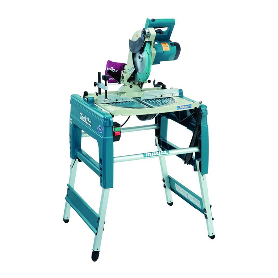
Makita LF1000 Instruction Manual
Flip over saw
Hide thumbs
Also See for LF1000:
- Instruction manual (180 pages) ,
- Instruction manuals (22 pages) ,
- Instruction manual (68 pages)
Table of Contents
Advertisement
Quick Links
Advertisement
Table of Contents

Related Manuals for Makita LF1000


Summary of Contents for Makita LF1000
- Page 1 INSTRUCTION MANUAL Flip over saw LF1000 DOUBLE INSULATION Read before use.
-
Page 2: Specifications
SPECIFICATIONS Model LF1000 Blade diameter 260 mm Blade body thickness 1.8 mm - 2.0 mm Riving knife thickness 2.2 mm Hole diameter For European countries 30 mm Max. Cutting capacities at 90°in the table saw (bench saw mode) 70 mm... -
Page 3: Ec Declaration Of Conformity
Power supply Work area safety The tool should be connected only to a power supply of the same Keep work area clean and well lit. Cluttered or voltage as indicated on the nameplate, and can only be operated dark areas invite accidents. on single-phase AC supply. - Page 4 Power tool use and care Do not use saw blades manufactured from high speed steel. 18. Do not force the power tool. Use the correct power tool for your application. The correct Wear eye protection. power tool will do the job better and safer at the Wear hearing protection to reduce the risk of rate for which it was designed.
-
Page 5: Installation
25. Be alert at all times, especially during repeti- 43. Hold the handle firmly. Be aware that the saw tive, monotonous operations. Do not be lulled moves up or down slightly during start-up and into a false sense of security. Blades are stopping. -
Page 6: Functional Description
When the tool is ready in the foot-folded position, secure Bench mounting the tool by using U-shaped grooves shown in the figure. For the fully-extended feet set up as the high table FUNCTIONAL DESCRIPTION When the tool cannot be set up stable, turn the adjust- ing nut at the foot of the tool for proper stability. - Page 7 After cleaning, always reinstall it securely. If any of these blade guards becomes discolored through age or UV light exposure, contact a Makita service center for a new guard. DO NOT DEFEAT OR REMOVE GUARDS.
-
Page 8: Adjusting The Miter Angle
Adjusting the miter angle ► 1. Handle To adjust the bevel angle, loosen the lever at the rear of ► 1. Clamping screw 2. Guide fence the tool counterclockwise. Push the handle to the left to tilt the saw blade until the pointer points to the desired angle on the bevel scale. -
Page 9: Switch Action
Switch action Adjusting the depth of cut ► 1. Switch in the miter saw mode 2. Switch in the ► 1. Cutting depth adjusting knob table saw mode 3. Lock-off button 4. Switch trigger The depth of cut can be adjusted by turning the cutting 5. - Page 10 Hex wrench storage ► 1. Hex wrench 2. Wrench holder The hex wrench is stored as shown in the figure. When using the hex wrench, pull it out of the wrench holder. After using the hex wrench, return it to the wrench holder. Table height two-way set up The table height can be set up in two ways, high or low table.
- Page 11 Always be sure that the tool is switched off and unplugged before installing or removing the blade. • Use only the Makita hex wrench provided to ► 1. Lever 2. Lifting lever install or remove the blade. Failure to do so may result in overtightening or insufficient tightening To install the blade, mount it carefully onto the spindle, of the hex socket bolt.
-
Page 12: Adjusting Riving Knife
Adjusting riving knife ► 1. Blade case 2. Arrow 3. Saw blade 4. Arrow NOTE: ► 1. Clamping nut 2. Hex socket bolt 3. Riving knife • When installing a saw blade, be sure to insert There must be a clearance of about 5 - 6 mm between it between the blade guard B at first and then the riving knife and the blade teeth when pushing the raise it so that the blade is finally placed in the... - Page 13 If they are not aligned for any reasons, always have Makita authorized service center repair it. • When adjusting the riving knife clearance from the blade teeth, always loosen the hex socket bolt only after loosening the clamping nut.
- Page 14 The rip fence is factory adjusted so that it is parallel to the CAUTION: blade surface. Make sure that it is parallel. To check to • Be sure to adjust the rip fence so that it is parallel with be sure that the rip fence is parallel with the blade, adjust the blade, or a dangerous kickback condition may occur.
-
Page 15: Securing Workpiece
The use of the dust bag makes cutting operations clean and dust Securing workpiece collection easy. To attach the dust bag, fit it onto the dust nozzle. When the dust bag is about half full, remove the dust bag from WARNING: the tool and pull the fastener out. - Page 16 2. Securing the tool head Position the vise arm according to the thickness and shape of the workpiece and secure the vise arm by tightening the clamping screw. If the screw to secure the vise arm contacts the guide fence, install the clamping screw on the opposite side of vise arm.
- Page 17 4. Repositioning the riving knife Fig.1 Fig.2 Fig.3 Fig.5 Fig.4 Fig.6 ► 1. Riving knife 2. Clamping nut The position (Fig. 1) should be changed as follows. 6. Locking the tool head at fully Loosen the clamping nut (Fig. 2). lowered position Pull and pivot the riving knife to the position at the angle of 90°...
- Page 18 CAUTION: CAUTION: • When the tool head cannot be locked in the fully • After installing the top blade guard, make sure lowered position, turn the depth adjusting knob that it works smoothly. by several turns clockwise. Setting up the tool in miter saw •...
-
Page 19: Operation
5. Repositioning riving knife Fig.3 Fig.2 Fig.1 Fig.4 Fig.5 ► 1. Riving knife 2. Clamping nut The position of riving knife (Fig. 1) should be changed 1. Press cutting as follows. Loosen the clamping nut and hold the lower blade guard A using its lug by hand (Fig. 2). While holding the lower blade guard A, pull the riving knife so that it turns and pivot it to the position in the direction of arrow (Fig. -
Page 20: Bevel Cut
3. Bevel cut 5. Cutting aluminum extrusion ► 1. Vise (accessory) ► 1. Vise 2. Spacer block 3. Guide fence 4. Aluminum extrusion 5. Spacer block Loosen the lever and tilt the saw blade to set the bevel angle (Refer to the previously covered When securing aluminum extrusions, use spacer "Adjusting the bevel angle"). -
Page 21: Work Helpers
Turn the tool on and gently feed the workpiece into Work helpers the blade along with the rip fence. When the width of rip is 150 mm and wider, Push sticks, push blocks or auxiliary fence are types of "work carefully use one hand to feed the work- helpers". -
Page 22: Miter Gauge
CAUTION: • Secure the knob on the miter gauge carefully. • Avoid creep of workpiece and gauge by firm work-holding arrangement, especially when cutting at an angle. • NEVER hold or grasp the intended "cut-off" portion of the workpiece. Use of miter gauge ►... -
Page 23: Carrying Tool
Carrying tool WARNING: • Always be sure that the blade is sharp and clean for the best and safest performance. Adjusting the cutting angle This tool is carefully adjusted and aligned at the factory, but rough handling may have affected the alignment. If your tool is not aligned properly, perform the following: 1. -
Page 24: Bevel Angle
2. Bevel angle ► 1. Arm 2. Bevel scale 3. Pointer 4. Turn table ► 1. 0° adjusting bolt 2. 45° adjusting bolt 45° bevel angle Adjust the 45° bevel angle only after per- 0° bevel angle forming 0° bevel angle adjustment. To adjust Lower the handle fully and lock it in the left 45°... -
Page 25: After Use
CAUTION: • These accessories or attachments are recom- mended for use with your Makita tool specified in this manual. The use of any other accessories or attachments might present a risk of injury to persons. Only use accessory or attachment for its stated purpose. - Page 28 Makita Europe N.V. Jan-Baptist Vinkstraat 2, 3070 Kortenberg, Belgium Makita Corporation 3-11-8, Sumiyoshi-cho, Anjo, Aichi 446-8502 Japan 884597L221 20200310 www.makita.com...