Table of Contents
Advertisement
Quick Links
DELTA ELEKTRONIKA B.V.
DC POWER SUPPLIES
SM3300 - series
• SM18-220
• SM66-AR-110
• SM100-AR-75
• SM330-AR-22
• SM660-AR-11
Firmware Update
It is strongly recommended, first to perform a firmware update before further
operation. Download the SM3300 Quick Start Manual for instructions.
Driver & Example Software
For several applications and Interfaces there is Driver & Example Software
available on our website. See PRODUCTS\SM3300\DOWNLOADS.
PRODUCT MANUAL
Firmware version P0157
Contents:
1
–
Safety Instructions
2
–
Sicherheitshinweise
3
–
Consignes de Sécurité
4
–
Quick Start
5
–
General
6
–
Installation
7
–
Front Menu Operation
8
–
Remote Programming
9
–
Trouble Shooting
10 –
Maintenance & Calibration
11 –
EU Declaration of Conformity
12 –
UK Declaration of Conformity
1 / 32
Vissersdijk 4, 4301 ND
Zierikzee, the Netherlands
DELTA ELEKTRONIKA B.V.
www.DeltaPowerSupplies.com
Tel. +31 111 413656
rev. June 2022
Advertisement
Table of Contents

Related Manuals for Delta Electronics SM3300 Series

Summary of Contents for Delta Electronics SM3300 Series
- Page 1 DELTA ELEKTRONIKA B.V. Vissersdijk 4, 4301 ND www.DeltaPowerSupplies.com Zierikzee, the Netherlands Tel. +31 111 413656 DC POWER SUPPLIES SM3300 - series • SM18-220 • SM66-AR-110 • SM100-AR-75 • SM330-AR-22 • SM660-AR-11 Firmware Update It is strongly recommended, first to perform a firmware update before further operation.
- Page 2 SAFETY INSTRUCTIONS SM3300 SAFETY INSTRUCTIONS – SM3300-series Caution The following safety precautions must be observed during all phases of operation, service and repair of this equipment. Failure to comply with the safety precautions or warnings in this document violates safety standards of design, manufacture and intended use of this equipment and may impair the built-in protections.
- Page 3 SAFETY INSTRUCTIONS SM3300 • Switch off the unit and disconnect the unit from the AC mains supply and from the DC power application. • Wait for 5 minutes to allow internal capacitors to discharge, then unscrew and remove the cover(s). •...
- Page 4 SAFETY INSTRUCTIONS SM3300 SICHERHEITSHINWEISE – SM3300-series Vorsicht Die folgenden Sicherheitsvorkehrungen müssen in allen Betriebs-, Service- und Reparaturphasen dieses Geräts befolgt werden. Die Nichteinhaltung der Sicherheitsvorkehrungen oder Warnungen in diesem Dokument verstößt gegen die Sicherheitsstandards im Hinblick auf Bauart, Produktion und vorgesehene Nutzung dieses Geräts und kann die eingebauten Schutzvorrichtungen beschädigen.
- Page 5 SAFETY INSTRUCTIONS SM3300 2.11 Entfernung von (Sicherheits-) Abdeckungen Sicherheitsabdeckung(en) werden verwendet, um potenziell gefährliche Spannungen abzudecken. Beachten Sie Folgendes, wenn Sie die Sicherheitsabdeckung(en) entfernen: • Gerät ausschalten, Gerät von dem AC-Versorgungsnetz und DC-Anwendung trennen. • Warten Sie 5 Minuten um interne Kondensatoren zu entladen. Abschrauben und entfernen von Abdeckung(en). •...
- Page 6 SAFETY INSTRUCTIONS SM3300 CONSIGNES DE SÉCURITÉ - Série SM3300 Mise en garde Les précautions de sécurité suivantes doivent être suivies dans toutes les phases de fonctionnement, d’entretien et de réparation de cet appareil. Le non-respect des précautions de sécurité ou des avertissements contenus dans le présent document enfreint les normes de sécurité...
- Page 7 SAFETY INSTRUCTIONS SM3300 3.11 Retrait des couvercles (de sécurité) Les couvercles de sécurité sont utilisés pour couvrir les tensions potentiellement dangereuses. Gardez les points suivants à l’esprit lorsque vous retirez le(s) couvercle(s) de sécurité : • Éteignez l’appareil, déconnectez-le du réseau d’alimentation CA et de l’application CC. •...
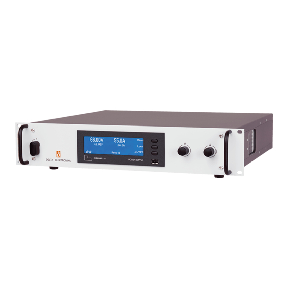
- Page 8 QUICK START SM3300 QUICK START – SM3300-series Connecting the unit V-knob A-knob Mains switch CON B1 & CON B2 CON D fig 4 - 1 - controls and connections. Warning! Never make connections to the Power Inputs, Power Outputs or Sense Connector when the unit is connected to the mains supply or power outlet! Safety covers are used to cover these in- and outputs.
- Page 9 QUICK START SM3300 actual voltage actual current 4.2.2 FIRST OPERATION • The first line in the front display indicates the actual output voltage and current. The second line shows the settings of the controls. • Check the text 'front' is indicated - this means the unit is in local-operation and can be controlled by the V-knob and A-knob at the front panel.
- Page 10 GENERAL SM3300 GENERAL DC OUTPUT • The SM18-220, SM66-AR-110, SM100-AR-75, SM330-AR-22 and SM660-AR-11 can either be used as a constant voltage source with current limiting or as a constant current source with voltage limiting. • The change of mode occurs sharply at the crossing of the voltage and current settings.
- Page 11 GENERAL SM3300 TURN ON DELAY • The output voltage is available very quickly after mains switch • In the datasheet the exact specifications can be found. INRUSH CURRENT • The inrush current is electronically limited. • Repeatedly switching on and off does not change the maximum peak current.
- Page 12 GENERAL SM3300 5.18 PARALLEL OPERATION • The power supplies can be connected in parallel without special precautions and limitations. • For easier control, the optional Master/Slave interface is recommended (see fig. 5 - 5 and fig. 5 - 6). By using the Master/Slave series interface, a dual tracking power supply can be made with one unit as master and one or more units as slave.
-
Page 13: Operating Temp
GENERAL SM3300 5.25 OPTIONAL POWER SINK • With optional power sink, the output voltage setting is maintained when there is power fed back into the unit. • Ideal for fast discharge of the output at no-load conditions. • For series operation in combination with Power Sink option, all units must have a Power Sink built inside otherwise no power can be absorbed. -
Page 14: Installation
INSTALLATION SM3300 INSTALLATION • Warning! carefully read the chapter "Safety Instructions" in this manual before connecting or operating the unit! Unit DC Output Bolts Torque cable [mm [Nm] HUMIDITY & CONDENSATION SM18-220 • During normal operation, humidity will not harm the power SM66-AR-110 supply, provided the air is not aggressive. - Page 15 INSTALLATION SM3300 • No neutral connection is required on a 3-phase grid. • For a single-phase grid, connect between L1 and L2. • After installation, connect the pull relief and add the safety cover over the input. 6.4.2 DC POWER TERMINALS •...
-
Page 16: Optional Interfaces
INSTALLATION SM3300 6.4.7 OPTIONAL INTERFACES • For programming via an optional interface, refer to the interface manual for installation and cable connections. INSULATION • The insulation of the separating components between input and output, such as transformers and opto-couplers, is tested before assembly during 1 minute @ 3750 Vrms (5300VDC). -
Page 17: Parallel Operation
INSTALLATION SM3300 • The operational isolation of SM18-220, SM66-AR-110 and SM100-AR-75 allows a total series voltage of 1000V. • The operational isolation of SM330-AR-22 and SM660-AR-11 allows a total series voltage of respectively 1330V and 1400V. • Warning! The minus power output of the unit is allowed to be maximum 1000VDC higher or lower than the Protective Earth, regardless of the higher allowed series voltage! •... -
Page 18: Battery Charger
INSTALLATION SM3300 a DC-motor), use a capacitor in series with a resistor over the Suggested circuit breakers for protection power supply load (see fig. 6 - 10). Like this the AC-component caused by Model Type nr. Brand Remarks the pulsing of the load is filtered. •... - Page 19 INSTALLATION SM3300 6.13.5 FRONT ICONS AC FAIL • This indicator is active if the input voltage is too low / too high. DC FAIL • This indicator is active if the output is 5% below or above the set value. OVER TEMPERATURE •...
-
Page 20: Accessing The Main Menu
FRONT MENU OPERATION SM3300 FRONT MENU OPERATION ACCESSING THE MAIN MENU • After switching on the unit, the right side of the display shows the texts 'Menu', 'Lock' and 'on/Off' (see fig. 7 - 1). Press the upper push button right from the text 'Menu' to enter the menu of the unit. - Page 21 FRONT MENU OPERATION SM3300 SOUNDS • Select the sound for each indicator separately. • Possible settings are 1xCHANGE, 3xCHANGE, • DOWNWARDS and CONTINUOUS BEEP. LANGUAGE For firmware package P0120 the language available is 'ENGLISH'. POWER-ON STATE VOLTAGE • Select CV setting of the unit after mains switch on. •...
-
Page 22: Firmware Updating
FRONT MENU OPERATION SM3300 7.3.3 PROTECTION ACCESS SECURITY CHANGE KEY • Select the 4-digit access key. • Default setting is '0000'. • In case of a forgotten access key see troubleshooting, chapter 8. LOCK OPTIONS • Select which functions are blocked with the 'LOCK' •... - Page 23 FRONT MENU OPERATION SM3300 • Note: when DHCP is enabled the IP-address can change, for example after a power cycle. • In the web interface, go to Administration -> Firmware. • Select "Choose File" and browse to the downloaded package. •...
-
Page 24: Source Settings
REMOTE PROGRAMMING SM3300 REMOTE PROGRAMMING SOURCE SETTINGS • Via the front menu, the source can be set to the required programming input via: Menu -> Configuration -> Source. • The possible settings for V-settings, I-settings and P- settings are: front encoders, ethernet, web interface, sequencer or an optional interface in rear slot1, 2, 3 or 4. - Page 25 REMOTE PROGRAMMING SM3300 • Enable / disable Power Sink. • Enable / disable Power Sink when Remote ShutDown status is high. • Enable / disable Power Sink when Interlock status is high. • Enable / disable Power Sink when the Output is Off. NETWORK •...
- Page 26 REMOTE PROGRAMMING SM3300 • The default password is "depower". • Passwords are not case sensitive. • In case of a forgotten password see next chapter Trouble Shooting. 8.2.4 DOCUMENTATION • Unit documentation in PDF-format available: - Safety instructions. - Unit operation and installation manual. - Interfaces operation and installation manual.
-
Page 27: Master / Slave Control
REMOTE PROGRAMMING SM3300 opto-isolated logic open drain outputs. • All in- and outputs have a common zero. • See datasheet and manual of the INT MOD DIG for more information. 8.5.4 ISOLATED CONTACTS • On this interface, there are 4 floating relay contacts available that can be controlled by Ethernet commands. -
Page 28: Troubleshooting
TROUBLE SHOOTING SM3300 TROUBLE SHOOTING GENERAL • If you have a question about the unit, please contact our engineers using the address Support@Delta-Elektronika.nl. • In case the unit is defect, please first fill out the RMA-form before sending the unit to us. Adding a detailed fault description will help us to repair the unit as soon as possible. - Page 29 TROUBLE SHOOTING SM3300 OT indicator blinks • The temperature of the internal heat sink is too high, the output has been shutdown to avoid overheating. • Check if the cooling fan is running. • Check if the air temperature of the air inlet (left) is below fig 9 - 4 If the OT-icon is shown on the display, the unit has 50 °C and the airflow is not obstructed.
-
Page 30: Maintenance And Calibration
MAINTENANCE & CALIBRATION SM3300 10 MAINTENANCE & CALIBRATION 10.1 GENERAL • The SM-series power supplies do not need any maintenance or calibration. However, care must be taken that the cooling unit is not obstructed. 10.2 COOLING FAN • The internal construction of the power supply is such that no dust will reach the sensitive control circuitry, only the heat fig 10 -1 sink in a tunnel will be cooled by forced air (see fig. - Page 31 EU DECLARATION SM3300 DELTA ELEKTRONIKA B.V. Vissersdijk 4, 4301 ND www.DeltaPowerSupplies.com Zierikzee, the Netherlands Tel. +31 111 413656 DC POWER SUPPLIES 11 EU Declaration of Conformity – SM3300-series Delta Elektronika Vissersdijk 4 4301 ND ZIERIKZEE The Netherlands Declare under sole responsibility that the following Power Supplies: SM18-220 SM66-AR-110 SM100-AR-75...
- Page 32 UK DECLARATION SM3300 DELTA ELEKTRONIKA B.V. Vissersdijk 4, 4301 ND www.DeltaPowerSupplies.com Zierikzee, the Netherlands Tel. +31 111 413656 DC POWER SUPPLIES 12 UK Declaration of Conformity – SM3300-series Product: SM3300 Power Supply Series Model Numbers: SM18-220, SM66-AR-110, SM100-AR-75, SM330-AR-22, SM660-AR-11. Manufacturer: Name: Delta Elektronika B.V.