
Related Manuals for GE Lanpro 33


Summary of Contents for GE Lanpro 33
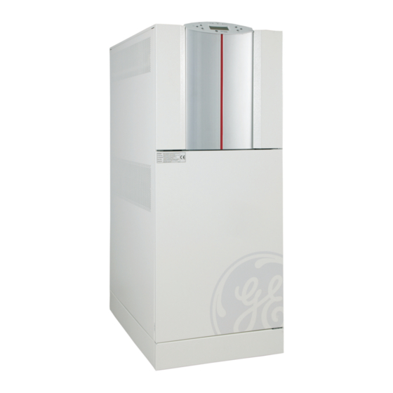
- Page 1 GE Digital Energy LanPro 33 Installation and commissioning guide Purpose of this document is to be a guide for the person in charge involved in the installation and the startup of the UPS, as a step by step procedure.
- Page 2 While every precaution has been taken to ensure the completeness • and accuracy of this document, assumes GE Digital Energy no responsability nor liability for damages or errors resulting from the the use of the information contained in this document. After unpacking the UPS(s) check carefully for any visible damages, which could have occurred during transport.
- Page 3 Cabinet Lanpro 33 Dimension Weigh Weight with rating W x D x H without standard Battery Battery 10kVA 500x780x 1280 113kg 247kg 20kVA 500x780x 1280 140kg 372kg 30kVA 660x780x 1280 172kg 520kg Panel remove Frontpanel Pressed on, remove with screw driver...
- Page 4 Panel and Display To access Function Measurements, Move to next page, metering Statistics and or scroll in edit ID-Number mode Move to previous page in metering Messages and alarms − and alarms, or in Alarms edit mode, change value Press to execute a command or enter Commands in edit mode to...
- Page 5 UPS Input / Output connection Cable sections (European standard) Input / Output 10kVA 20kVA 30kVA 5 x 4 mm2 5 x 10 mm2 5 x 10 mm2 Use the eyelet terminals from the plastic bag, for the connection of Neutrals and Earth to Input / Output.
- Page 6 UPS Frontview with Frontdoor open...
-
Page 7: Installation
UPS commissioning procedures (Standard product, single UPS) Preliminary and mechanical checks After unpacking and placing of the UPS, verify for any mechanical damage. Do never try to startup a damaged UPS. Make sure to maintain a minimum clearance of 10cm of the UPS’s lateral parts, for adequate ventilation with UPS’s on wheels. -
Page 8: System Checks
System checks Switch ON the Mains (Utility) voltage from the input distribution. At this stage the electronic power supply is switched ON and at the end of a selftest on the display should appear “SELF TEST OK” and the buzzer sounds, followed by showing the main page. - Page 9 Listing of second level Parameters Below a listing of the Parameters: • Battery type • Floating voltage adjust • Battery capacity • Battery charge current limitation • Number of Battery cells • Autonomy (Backup) time in Minutes • Stop operation time in Battery discharge •...
- Page 10 Startup in Service Mode (Q1 open) Connect Mains voltage (Utility) to the UPS. The Electronics are now powered. Control selftest on the display. At the end of selftest, the first page is displayed Example of first page (Series 0) The yellow LED on the Frontpanel should now be constantly ON, indicating Q1 to be open, thus the UPS in service mode.
- Page 11 • Insert Battery fuses and verify that after a few seconds in the first measurement screen for Ubp / Ubn, if the floating voltage with charged battery has reached it’s nominal value of +/- 270 V, +/- 3V. In case of discharged Battery this value can be lower, the Battery charger would run then in current limitation.
- Page 12 Startup in normal mode (Q1 closed) Connect Mains voltage (Utility) to the UPS. The Electronics are now powered. Control selftest on the display. At the end of selftest, the first page is displayed. The yellow LED on the Frontpanel should now be constantly ON, indicating that Q1 open, thus the UPS in service mode.