
Related Manuals for Johnson Controls SABROE ChillPAC


Summary of Contents for Johnson Controls SABROE ChillPAC
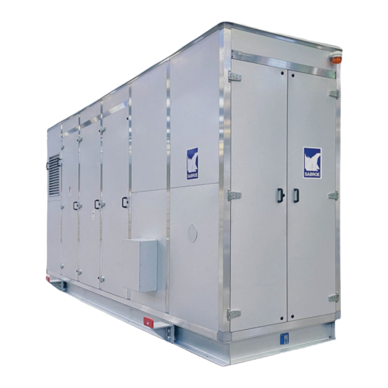
- Page 1 Installation and operation manual Sabroe enclosure for ChillPAC, HeatPAC and ChillPAC LP...
-
Page 3: Table Of Contents
Contents Introduction ..................4 Transport ....................5 Transport ..................5 Lifting the enclosure ..............5 Fixing the enclosure during transport ..........6 Enclosed trailer ................6 Transport security ................6 Installation on site .................7 Panel adjustment .................7 Lifting brackets ................8 Safety relief system ..............8 Electrical connection ..............9 Settings for heating panels ............9 Drain connection ................ -
Page 4: Introduction
Introduction 1. Introduction This manual contains guidelines for transport, installation and service of the Sabroe enclosure and instructions on how to ensure access to the equipment inside the enclosure. Installation and operation manual 4/20 0013321 en 2022.05... -
Page 5: Transport
Transport 2. Transport Transport The enclosure is top heavy. See the centre of gravity location on the specific GA drawings. Lifting the enclosure A crane, which can lift the stated weight of the enclosure, is required. Further, a lifting yoke must be used to make sure the panel plates are not damaged when lifted, see Fig. -
Page 6: Fixing The Enclosure During Transport
Transport Fixing the enclosure during transport Place the enclosure on straws and fasten it by lashing straps to prevent it from tipping during transport, see Fig. 2. Truck Fig. 2 Enclosed trailer The best way to transport the enclosure is in an enclosed mega trailer. Customised enclosures that cannot be transported in an enclosed trailer must NOT be covered by a tarpaulin instead, as the tarpaulin may damage the panels. -
Page 7: Installation On Site
Installation on site 3. Installation on site Panel adjustment The door hinges may loosen a little during transport so that the door is sagging or crooked on delivery, and this may cause the door to hit the aluminum profile (indicated by the green ar- rows). -
Page 8: Lifting Brackets
Installation on site Lifting brackets When the enclosure is placed on site, the lifting bracket should be disassembled and stored, if needed. See Fig. 6. Fig. 6 Safety relief system Remove the plug or tape to assemble the rest of the safety relief system with the included pipe fittings. -
Page 9: Electrical Connection
Installation on site Electrical connection The enclosure is supplied with a reinforced panel for cable lead-in. The exact location of the re- inforced panel is shown in the GA drawing, see also Fig. 9. The panel section is reinforced with a glued double outer plate to mount cable glands for cable entry. -
Page 10: Drain Connection
Installation on site Drain connection The enclosure has two drain pipes on the side of the base frame. They serve as drain for the entire floor of the enclosure. The drain pipes are 50 mm Blücher EuroPipes. Fig. 12: Drain on the enclosure Installation and operation manual 10/20 0013321 en 2022.05... -
Page 11: Service Of The Plant And Enclosure
Service of the plant and enclosure 4. Service of the plant and enclosure Safety Safety box The enclosure is classified as a machinery room. As the room is not part of a building, some re- quirements can be waived. There is light inside and an emergency exit sign above the doors. Manual control of the fans, main switch and emergency stop is possible from the front of the safety box. -
Page 12: Area Classification
Service of the plant and enclosure Area classification All refrigerant-containing parts are located in a ventilated enclosure or open air. The ventilated enclosure is classified as a machinery room, and the requirements for a class III location are applied (EN 378). As a unit, the enclosure is intended for use in normal areas;... -
Page 13: Leak Detection System
Service of the plant and enclosure Leak detection system The leak detection system has two levels: • Level A: High level - Emergency stop • Level B: Low level - Alarm Level A Normal Level B Function operation High level Low level Refrigerant detector Evacuation fan... -
Page 14: Access For Service
Service of the plant and enclosure Access for service Fig. 15 - Fig. 17 show the access options for a specific “6 high” version enclosure. The number of sections and the positioning of doors may vary depending on the plant inside. However, in general, access will be possible as shown in Fig. - Page 15 Service of the plant and enclosure Opening the doors The doors provide the main access. They are locked in the top, middle and at the bottom. Use the supplied square key to unlock the three latches, see Fig. 18. Fig. 19 shows how the open door provides access to part of the compressor and the WHC system.
-
Page 16: Sensors
Service of the plant and enclosure Sensors Two sensors are mounted at the top of the enclosure: one for ammonia and one for ventilation. Fig. 21 Fig. 22 Fig. 21 shows the ammonia detector, which activates the ventilation system at certain quanti- ties (350 mg/m starts a prealarm) and gives signal to turn off the power to the plant at other quantities (21,200 mg/m... -
Page 17: Ventilation
Service of the plant and enclosure Ventilation Check regularly that the ventilation filter is not clogged with dirt. The filter is accessible from the inside of the door panel, see Fig. 23 and Fig. 24. Fig. 23 Fig. 24 Oil trap for protection of safety valves Check regularly that the oil trap has oil. -
Page 18: Siren And Alarm
Service of the plant and enclosure Siren and alarm Do NOT open the door, if the siren and alarm are on. If the siren and alarm are on, gas has been detected. The detection will also activate the venti- lation system to let fresh air into the enclosure and ensure that the gas concentration cannot cause explosion hazard. - Page 19 Service of the plant and enclosure Major service or replacement of compressor/motor If there is not enough space to pull out the crankshaft, the entire compressor must be pulled out sideways from the enclosure. The compressor or motor can be pulled out by using a forklift, sliding bench or a lightweight portable gantry crane.
-
Page 20: Appendix
Appendix 5. Appendix Please find electrical drawings for the Sabroe enclosure in the following pages. Installation and operation manual 20/20 0013321 en 2022.05... - Page 22 Johnson Controls Denmark ApS Sabroe Factory Christian X's Vej 201 ∙ 8270 Højbjerg Denmark Phone +45 87 36 70 00 www.sabroe.com Version 3...
- Page 23 Johnson Controls Denmark ApS Christian X's Vej 201 DK-8270 Højbjerg, Denmark www.sabroe.com...
- Page 24 Johnson Controls Denmark ApS Christian X's Vej 201 DK-8270 Højbjerg, Denmark www.sabroe.com...
- Page 25 Johnson Controls Denmark ApS Christian X's Vej 201 DK-8270 Højbjerg, Denmark www.sabroe.com...
- Page 26 Johnson Controls Denmark ApS Christian X's Vej 201 DK-8270 Højbjerg, Denmark www.sabroe.com...
- Page 27 Johnson Controls Denmark ApS Christian X's Vej 201 DK-8270 Højbjerg, Denmark www.sabroe.com...
- Page 28 Johnson Controls Denmark ApS Christian X's Vej 201 DK-8270 Højbjerg, Denmark www.sabroe.com...
- Page 29 Sectional side view Mounting plate Johnson Controls Denmark ApS Christian X's Vej 201 DK-8270 Højbjerg, Denmark www.sabroe.com...
- Page 30 Johnson Controls Denmark ApS Christian X's Vej 201 DK-8270 Højbjerg, Denmark www.sabroe.com...
- Page 31 Johnson Controls Denmark ApS Christian X's Vej 201 DK-8270 Højbjerg, Denmark www.sabroe.com...
- Page 32 Johnson Controls Denmark ApS Christian X's Vej 201 DK-8270 Højbjerg, Denmark www.sabroe.com...
- Page 33 Johnson Controls Denmark ApS Christian X's Vej 201 DK-8270 Højbjerg, Denmark www.sabroe.com...
- Page 34 Johnson Controls Denmark ApS Christian X's Vej 201 DK-8270 Højbjerg, Denmark www.sabroe.com...