Makita DTW700 Instruction Manual
Hide thumbs
Also See for DTW700:
- Instruction manual (101 pages) ,
- Instruction manual (100 pages) ,
- Instruction manual (80 pages)

Related Manuals for Makita DTW700


Summary of Contents for Makita DTW700
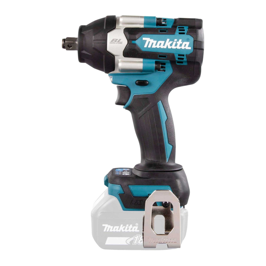
- Page 1 INSTRUCTION MANUAL Cordless Impact Wrench DTW700 DTW700XV DTW701 DTW701XV Read before use.
-
Page 2: Specifications
Noise meaning before use. Read instruction manual. The typical A-weighted noise level determined accord- ing to EN62841-2-1: Model DTW700 Only for EU countries Ni-MH Sound pressure level (L ) : 94 dB (A) Due to the presence of hazardous components in the... -
Page 3: Ec Declaration Of Conformity
The vibration total value (tri-axial vector sum) deter- Work area safety mined according to EN62841-2-1: Keep work area clean and well lit. Cluttered or Model DTW700 dark areas invite accidents. Work mode: impact tightening of fasteners of the maxi- Do not operate power tools in explosive atmo-... - Page 4 Use personal protective equipment. Always Disconnect the plug from the power source wear eye protection. Protective equipment such and/or remove the battery pack, if detachable, from the power tool before making any adjust- as a dust mask, non-skid safety shoes, hard hat or ments, changing accessories, or storing power hearing protection used for appropriate conditions will reduce personal injuries.
- Page 5 DO NOT let comfort or familiarity 12. Use the batteries only with the products with product (gained from repeated use) replace specified by Makita. Installing the batteries to strict adherence to safety rules for the subject non-compliant products may result in a fire, exces- product.
-
Page 6: Functional Description
If you can see the red indicator as causing fires, personal injury and damage. It will also shown in the figure, it is not locked completely. void the Makita warranty for the Makita tool and charger. CAUTION: Always install the battery cartridge Tips for maintaining maximum fully until the red indicator cannot be seen. - Page 7 Lighting up the front lamp Indicator lamps Remaining capacity CAUTION: Do not look in the light or see the Lighted Blinking source of light directly. 75% to 100% 50% to 75% 25% to 50% 0% to 25% Charge the battery. The battery may have malfunctioned.
- Page 8 Reversing switch action Fig.6 ► 1. Reversing switch lever CAUTION: Always check the direction of rotation before operation. CAUTION: Use the reversing switch only after the tool comes to a complete stop. Changing the direction of rotation before the tool stops may dam- age the tool.
-
Page 9: Changing The Application Mode
Changing the application mode Changing the impact force You can change the impact force in four steps: 4 (max), 3 (hard), 2 (medium), and 1 (soft). This allows a tightening suitable to the work. The level of the impact force changes every time you press the button You can change the impact force within approximately one minute after releasing the switch trigger. - Page 10 Changing the application mode This tool employs several easy-to-use application modes for driving bolts with good control. The type of the application mode changes every time you press the button You can change the application mode within approximately one minute after releasing the switch trigger. NOTE: You can extend the time to change the application mode approximately one minute if you press the but- Fig.8 Application mode...
- Page 11 NOTE: The way of impact socket installation varies depending on the type of the square drive on the tool. Tool with the ring spring Fig.9 Model DTW700 / DTW700XV ► 1. Button 2. Lamp For impact socket without O-ring and pin...
-
Page 12: Installing Hook
For impact socket with O-ring and pin For tool with firm fit detent pin Optional accessory Fig.11 ► 1. Impact socket 2. O-ring 3. Pin Fig.13 ► 1. Impact socket 2. Hole 3. Square drive 4. Detent Move the O-ring out of the groove in the impact socket and remove the pin from the impact socket. -
Page 13: Operation
The hook is convenient for temporarily hanging the tool. OPERATION This can be installed on either side of the tool. To install the hook, insert it into a groove in the tool housing on either side and then secure it with a screw. To remove, CAUTION: Always insert the battery cartridge loosen the screw and then take it out. -
Page 14: Maintenance
Discoloration, deformation or cracks may result. (2040) To maintain product SAFETY and RELIABILITY, repairs, any other maintenance or adjustment should be performed by Makita Authorized or Factory Service Centers, always using Makita replacement parts. (1020) OPTIONAL ACCESSORIES 1. - Page 16 Makita Europe N.V. Jan-Baptist Vinkstraat 2, 3070 Kortenberg, Belgium Makita Corporation 3-11-8, Sumiyoshi-cho, Anjo, Aichi 446-8502 Japan 885799C222 www.makita.com 20220325...