Table of Contents
Advertisement
Quick Links
Advertisement
Chapters
Table of Contents
Troubleshooting

Related Manuals for Johnson Controls SABROE UniSAB III


Summary of Contents for Johnson Controls SABROE UniSAB III
- Page 1 Engineering manual UniSAB III control Version 1.10.8...
- Page 3 Compressor type ____________________ Refrigerant _____________ Shop no. ________________________________________ Password ________________________________________ Software version ________________________________________ Engineering manual - UniSAB III Control Control system for refrigerating compressors Version 1.10.8 Engineering manual - UniSAB III 1.10.8 001930 en 2021.06 3/346...
- Page 4 Copyright © Johnson Controls Denmark This manual must not be copied without the written permission of Johnson Controls Denmark and the contents must not be imparted to a third party nor be used for any unauthorised purpose. Contravention will be prosecuted.
- Page 5 Whenever the emergency stop is activated during operation, the alarm text Compr. motor error will ap- pear in the display. Before the compressor can be restarted, deactivate the alarm by means of the /RESET key and release the emergency stop. Note: If UniSAB III is set at Remote or Auto, the compressor will restart automatically.
-
Page 6: Table Of Contents
Contents UniSAB III control ................14 Introduction ................14 Operating the UniSAB III control ..........15 1.2.1 Start-up ................15 1.2.2 Display ................17 1.2.3 Front panel ................. 18 1.2.4 Menu structure ..............19 1.2.5 Session ................28 1.2.6 Changing set values ............31 1.2.7 Favourites ................ - Page 7 2.2.13 Cooling fan error ..............54 2.2.14 Oil rectifier error ..............54 2.2.15 Wrong starting number in sequence ........55 2.2.16 Limiting suction pressure ............. 55 2.2.17 Limiting discharge pressure ..........55 2.2.18 Limiting process out temperature ......... 55 2.2.19 Limiting hot water ..............
- Page 8 Shutdowns and alarms list with id nos.......... 64 2.3.1 Shutdowns and alarms for screw compressors ...... 64 2.3.2 Shutdowns and alarms for reciprocating compressors ... 67 Compressor control and surveillance ..........69 Compressor regulation set-up ............. 69 3.1.1 Control mode set-up ............69 3.1.2 Regulator set-up ..............
- Page 9 3.3.17 SAB 120 and 151 without oil pump ........113 3.3.18 SAB 193, 233, 283 and 355 with oil pump ......114 3.3.19 SAB 193, 233, 283 and 355 without oil pump ...... 115 3.3.20 SABCube 109, 133 and 159 ..........116 3.3.21 SAB 157 HR ..............
- Page 10 Compressor control - adjusting slide speed (screw compressors with hydraulic slides) ........150 3.7.1 Capacity slide ..............150 3.7.2 Volume ratio slide ............. 150 Compressor control - variable zero position (screw compres- sors with hydraulic slides) ............151 3.8.1 General ................151 3.8.2 Corrected capacity ............
- Page 11 Set-up ....................180 Compressor control ..............180 6.1.1 Compressor operating set-up ..........180 Sequencing ................182 6.2.1 Multisab sequencing ............182 6.2.2 Sequencing parameters ............ 182 6.2.3 Sequencing status info ............184 Multisab .................. 185 6.3.1 Multisab ................185 Configuration ................188 6.4.1 Drive ................
- Page 12 6.6.5 Function interface ............. 255 6.6.6 E-mail ................257 6.6.7 Language ................. 257 Calibration ..................258 Before start-up ................. 258 Pressure transducers ............... 258 Temperature sensors (process out temperature) ......260 Motor ..................260 7.4.1 Motor frequency signal ............260 7.4.2 Motor current ..............
- Page 13 8.3.3 Uploading new/additional language ........279 Info ..................279 8.4.1 Flash ................280 8.4.2 Ethernet, IP address set-up ..........281 8.4.3 File system ............... 283 8.4.4 Contrast (display) ............. 283 Communication set-up ............. 285 8.5.1 Connection overview ............285 8.5.2 Configuration of Ethernet channel ........
-
Page 14: Unisab Iii Control
UniSAB III control 1. UniSAB III control Introduction The purpose of the UniSAB III control system is to monitor, protect, control and regulate reciprocating and screw compressors. The control cabinet as well as the electrical components have been connected from factory. Thus, only a few connections are needed to link to the electrical installations on site. UniSAB III is programmed according to the type of compressor it is going to control. -
Page 15: Operating The Unisab Iii Control
UniSAB III control Operating the UniSAB III control 1.2.1 Start-up On delivery all electrical components in the compressor are connected to UniSAB III. On site it is only necessary to add the correct supply voltage from the local installations. The electric wiring must be car- ried out according to the wiring diagrams for UniSAB III at the end of this manual. - Page 16 UniSAB III control Fig. 2: UniSAB III with front open This way the front panel remains easy to operate and easy access to the cabinet interior is obtained. When UniSAB III is open, it is still fully operational. Engineering manual - UniSAB III 1.10.8 16/346 001930 en 2021.06...
-
Page 17: Display
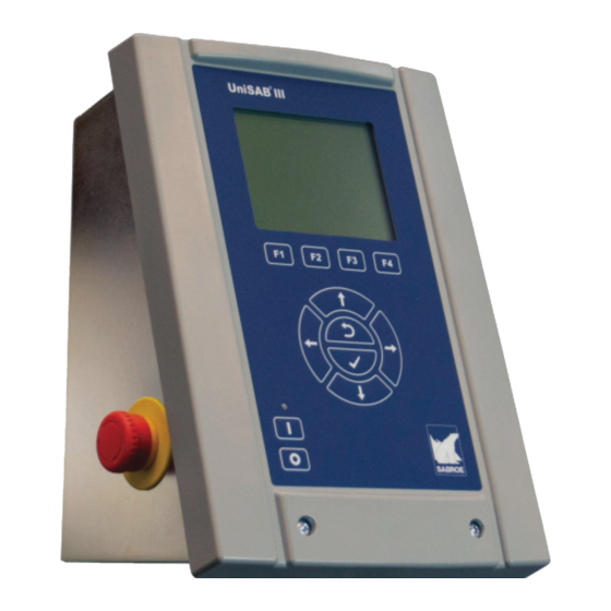
UniSAB III control 1.2.2 Display Top bar Content area Info bar F-key area Fig. 3: UniSAB III front Display The display has a background illumination with screen saver function. It consists of a top bar with navi- gation information, a content area with 7-11 lines of information, an info bar with mode and status infor- mation and an F-key area with information about the active function keys. -
Page 18: Front Panel
The Enter (check) key has several functions. When changing the set values, pressing this key will enter the change into the UniSAB III memory. To make changes, you must use the password provided by Johnson Controls Denmark. As to the encoding of a password, see subsection 1.2.6 Changing set values. -
Page 19: Menu Structure
UniSAB III control F-key section Function key 1. Has several functions, e.g. jumping to the Favourites/Default picture. Function key 2. Has several functions, e. g. increasing capacity during manual operation. If there is a scroll bar to the right in the picture the key has a PAGE UP function. - Page 20 UniSAB III control UniSAB III HMI menu tree Bold text = menu Normal text = a selectable picture Menu level 1 Menu level 2 Menu level 3 Menu level 4 Favourites Default User 1 User 2 User 3 User 4 User 5 User 6 Manage...
- Page 21 UniSAB III control Menu level 1 Menu level 2 Menu level 3 Menu level 4 Control values Suction Values Pressure Bar Limits Control Pressure Deg. Limits Control Superheat Limits Control Pressure gradient Limits (default enabled for heat pump compr.) Internal suction pressure Limits (SABflex, SABCube) Control (SABflex, SABCube) Internal pressure...
- Page 22 UniSAB III control Menu level 1 Menu level 2 Menu level 3 Menu level 4 Control values Values Pressure Limits Control Filter Limits pressure Pump Limits (SAB 120-151, SAB 193-355, SAB 193 H-355 H, SAB 157 HR, SAB 273 S) (SAB 80, S70, S50, S93) Temperature Limits Control...
- Page 23 UniSAB III control Menu level 1 Menu level 2 Menu level 3 Menu level 4 Control values Motor Values Current Control Power Control Speed Control (VSD only) Speed ref. (VSD/Modbus only) Frequency (VSD/Modbus only) /DA Final speed (VSD/Modbus only) /LS Voltage (VSD/Modbus only) Torque Nm...
- Page 24 UniSAB III control Menu level 1 Menu level 2 Menu level 3 Menu level 4 Control values Process temp. Values Process out temp. Limits (Chiller only) Control (Chiller only) Process in temp. Limits (Chiller only) Liquid level Control (LP/HP control) Suction superheat Control (DX control) User...
- Page 25 UniSAB III control Menu level 1 Menu level 2 Menu level 3 Menu level 4 Service Maintenance Service timers Maint. compr. Drive (VSD/Modbus only) Diagnosis Hardware Analogue inputs Analogue outputs Digital inputs Digital outputs Software Software version Power on Zero cap. pos. (screws only) Proficom Rotatune piston (rota rec.
- Page 26 UniSAB III control Menu level 1 Menu level 2 Menu level 3 Menu level 4 Setup Compr. Control Sequencing Multisab Configuration Drive (VSD/Modbus only) Compressor Block Plant Oil system Communication Dig. in by Com. (If Dig input by Com) Measuring External input Aux.
- Page 27 UniSAB III control Menu level 1 Menu level 2 Menu level 3 Menu level 4 Setup Configuration Calibration Pressure Process temperature Position Frequency Analogue input Analogue output Digital input Digital output Quick set up Factory reset Timers Timer list (Recip./Screw) Timer setup (Recip./Screw) Date - Time...
-
Page 28: Session
User - access to change set points linked to normal operation • Superuser - access to change configuration and critical set points • Supervisor - Johnson Controls Denmark supervisor level Switch between the password levels with . Choose the appropriate level with and enter the four digit password using the arrow keys. - Page 29 Session menu. Log in at the level where you want to change your password and en- ter your new password. Make sure you remember your new password as you will need to contact Johnson Controls Denmark in order to have the password re-established if you forget it. User interface The user interface appearance can be changed (see subsection 1.2.6 Changing set values).
- Page 30 UniSAB III control Languages Like any other function setting (see subsection 1.2.6 Changing set values) the language can be changed to any of the following, even when the compressor is running: en=English fi=Finnish fr=French es=Spanish da=Danish de=German cs=Czech sv=Swedish ru=Russian pl=Polish pt=Portuguese nl=Dutch it=Italian no=Norwegian hu=Hungarian el=Greek tr=Turkish pt-BR=Brazilian ko=Korean When UniSAB III is switched on for the first time the set language will be English (en).
-
Page 31: Changing Set Values
UniSAB III control 1.2.6 Changing set values This example illustrates how to change set values such as alarm limits, shutdown limits, set points and timer starting value. First you must position the (dark) cursor on the value you want to change. In this ex- ample it is the Low shutdown limit for suction pressure. - Page 32 UniSAB III control Switch between the password levels with the keys. When you have selected the appropriate level with the key, you must enter in this case the four digit Superuser password using the arrow keys. When you have entered the four digits, press /OK.
-
Page 33: Favourites
UniSAB III control 1.2.7 Favourites Favourites contain a number of overview pictures for daily compressor operation. There is one prede- fined favourite picture designated as Default. The other six favourite pictures are user definable, named User 1 to User 6. Each favourite picture may contain up to seven parameters. The User 1 to User 6 favourites pictures are as the name indicates user definable. - Page 34 UniSAB III control UniSAB III automatically skips back to the Manage Favourites picture. In this picture, place the cursor on the user picture you want to insert the value into, e.g. the User 1 favourite. Press /CONFIRM to in- sert the actual setpoint into User 1. Press /OK to continue bookmarking.
-
Page 35: Manual And Auto Operation
UniSAB III control 1.2.8 Manual and auto operation Select compressor control mode Compressor control mode, i. e. Stopped, Manual, Auto or Remote operation, is selected in the Setup menu in the Compr Control picture. Alternate between manual and auto/remote control mode In the Default or any User favourites picture (if set up by the user) you may set Manual Mode to “Yes”, i. -
Page 36: Shutdown And Alarm Acknowledgement
UniSAB III control Manual stop You can stop the compressor immediately by pressing . Compressor status in the info bar will be cap. slide down or pause depending on compressor type. The light diode above the start key will be off. For SAB 109, 133 and 159 you will experience a time delay from pressing the stop key and until the compressor stops. -
Page 37: Factory Settings
UniSAB III control 1.2.10 Factory settings On delivery UniSAB III is preset with factory settings for all appropriate points. Although other values may have been entered from factory or after delivery, UniSAB III can always be reset to its factory set- tings. -
Page 38: Alarms And Shutdowns
Alarms and shutdowns 2. Alarms and shutdowns Analogue alarms and shutdowns 2.1.1 Introduction Shutdown and alarm limits can be set separately as described in subsection 1.2.6 Changing set values. UniSAB III does not check whether shutdown and alarm limits have been interchanged by mistake (e.g. if alarm limit for high discharge pressure is set higher than the shutdown limit). -
Page 39: Measured And Calculated Pressure Levels - Screws
Alarms and shutdowns 2.1.2 Measured and calculated pressure levels - screws Measuring Min. Max. Factory Note High shutdown High alarm 3+4+5+33 Suction pressure (bar) -1.0 Low alarm 3+4+5 -1.0 Low shutdown 3+4+5 High shutdown Suction pressure (bar) 22.0 19.0 3+4+5 High alarm -1.0 20.0... - Page 40 Alarms and shutdowns Measuring Min. Max. Factory Note Oil pressure (bar) Low alarm Calculated value Low shutdown SAB Mk 1 compressors Oil pressure (bar) Low alarm Calculated value Low shutdown SAB Mk 2 compressors Oil pressure (bar) Low alarm Calculated value Low shutdown SAB Mk 3, Mk 4 compressors Set point 1...
- Page 41 Alarms and shutdowns Measuring Min. Max. Factory Note Diff. pressure across oil filter (bar) High shutdown 2+11b Calculated value High alarm 2+11b SAB 120-151 and SAB 193-233-283-355 Diff. pressure across oil filter High shutdown 2+11b (bar) High alarm 2+11b Calculated value Low alarm SAB 157HR, SAB 273S Low shutdown...
-
Page 42: Measured And Calculated Temperatures - Screws
Alarms and shutdowns 2.1.3 Measured and calculated temperatures - screws Measuring Min. Max. Factory Note High shutdown 60.0 130.0 100.0 High alarm 50.0 120.0 90.0 Discharge temperature (°C) Low alarm -65.0 -65.0 -65.0 Low shutdown High shutdown 60.0 170.0 120.0 High alarm Discharge temperature (°C) 50.0... -
Page 43: Measured And Calculated Pressure Levels - Recips
Alarms and shutdowns Measuring Min. Max. Factory Note High shutdown 120.0 110.0 2+7+12 Suction gas superheat (°C) High alarm 120.0 100.0 2+7+12 Calculated value Low alarm 40.0 2+7+10 Low shutdown 40.0 2+7+10 Low alarm 40.0 15.0 2+7+10 Low shutdown Discharge gas superheat (°C) 40.0 10.0 2+7+10... -
Page 44: Measured And Calculated Temperatures - Recips
Alarms and shutdowns 2.1.5 Measured and calculated temperatures - recips. Measuring Min. Max. Factory Note High shutdown 60.0 155.0 125.0 High alarm 50.0 155.0 120.0 Discharge temperature (°C) Low alarm -65.0 -65.0 -65.0 Low shutdown High shutdown 40.0 105.0 80.0 High alarm Oil temperature (°C) 30.0... -
Page 45: Measured/Calculated Pressure Levels/Temp. - Hpo/Hpc/Hpx
Alarms and shutdowns 2.1.6 Measured/calculated pressure levels/temp. - HPO/HPC/HPX Measuring Min. Max. Factory Note High shutdown Suction pressure 25.0 10.0 3+4+5 High alarm (bar) -1.0 25.0 3+4+5 Low alarm -1.0 25.0 3+4+5 Low shutdown Suction pressure gradient (bar/ High shutdown min) 0.10 5.00... -
Page 46: Notes
Alarms and shutdowns Measuring Min. Max. Factory Note High shutdown 100.0 60.0 Process in temperature High alarm 100.0 50.0 (°C) Low alarm -100 100.0 Low shutdown -100 100.0 High shutdown 120.0 110.0 Suction gas superheat High alarm 120.0 100.0 (°C) Low alarm 40.0 2+10+13... - Page 47 Alarms and shutdowns Note 10 A 0.0 setting disables alarm/shutdown monitoring. Note 11a 300 sec. delay, regardless of when limits are exceeded. Note 11b 600 sec. delay, regardless of when limits are exceeded. Note 12 The compressor must have been above 5% capacity. When below 5% capacity alarm/shutdown monitoring is disabled.
- Page 48 Alarms and shutdowns than the liquid slugging alarm/shutdown set point for a fixed 5-second period. Set point 1 = alarm set point. Set point 2 = shutdown set point. Note 24 Oil temperature settings on heat pumps should be increased to: High shutdown: 95 High alarm: 90 Low alarm: 55...
- Page 49 Alarms and shutdowns Note 35 For HPC compressors released for 50 bar design pressure (Mk 4 LL or newer), the max. settings for discharge pressure high alarm and high shutdown are raised to 44.0/45.0 bar. For HPC compressors released for 40 bar design pressure (Mk 4 or older), the max.
- Page 50 Alarms and shutdowns grad. Note 39 For SAB 193 H, 233 H, 283 H, 355 H and SAB 273 S screw compressors, the internal pressure inside the compressor block is calculated as follows: Internal pressure = P * Vi suct,abs Where the Vi parameter is a function of the actual volume ratio of the compressor, depending on whether the economizer is activated or not.
-
Page 51: Oil Pressure Calculations
Alarms and shutdowns 2.1.8 Oil pressure calculations SAB 80 Oil separator Oil filter Oil pump Compressor Oil cooler Others Oil separator Oil filter Oil pump Compressor Oil cooler SABflex and SABCube Oil separator Oil filter Compressor Oil cooler Internal suction pressure Oil pressure Suction pressure (SABflex and SABCube) -
Page 52: Suction Gas Superheat, Shutdown
Alarms and shutdowns 2.1.9 Suction gas superheat, shutdown The suction gas superheat shutdown is a shutdown which in many cases will protect the compressor against liquid slugging. However, many aspects may affect superheating and therefore this shutdown must not be considered full protection against liquid slugging. If the superheat falls below the set value, the compressor stops. -
Page 53: Capacity Error (Screw Compressors)
Alarms and shutdowns For SAB 80/GSV-RWF/SAB 120-151, SAB 193-355, SAB 193 H-355 H, SAB 157 HR and SAB 273 S, this is an oil separator level shutdown. For SAB 109-159 this is an oil separator level shutdown. 2.2.3 Capacity error (screw compressors) This shutdown/alarm is not active for SABflex and SABCube compressors (SAB 109→... -
Page 54: Compressor Motor Overload
Alarms and shutdowns 2.2.7 Compressor motor overload The reason for the shutdown is that within the time set in the Current overload timer, a motor current has been measured continually. This current exceeds the actual set point value set for Motor current in Set point 1 or Set point 2. -
Page 55: Wrong Starting Number In Sequence
Alarms and shutdowns 2.2.15 Wrong starting number in sequence The reason for the alarm is that two or more compressors have the same starting number and the same system number. 2.2.16 Limiting suction pressure The alarm indicates that the suction pressure limiter is active, i.e. the suction pressure is within the limit- er neutral zone or below the alarm limit. -
Page 56: Watch The Oil Pressure
Alarms and shutdowns 2.2.24 Watch the oil pressure The alarm will be activated if the oil pump for oil charging is started by means of the picture Timers/Oil charging and the compressor is in operation at the same time. 2.2.25 Low lubricating pressure monitoring (screw compressor) The reason for this shutdown is that the differential pressure across the compressor and thus the effec- tive lubricating pressure are too low. -
Page 57: Insufficient Main Oil Pressure Alarm
Alarms and shutdowns Note that in version 1.10.7, this shutdown also covers SAB 193 H, 233 H, 283 H and 355 H. 2.2.31 Insufficient main oil pressure alarm SGC compressors (SAB 157 HR) This alarm is released if the oil pressure is < [1.5 x P ] + 1 bar. -
Page 58: Oil Pump Low Pressure Shutdown
Alarms and shutdowns excess pressure is calculated as the difference between oil pressure before filter (P4) and the discharge pressure (P2). 2.2.37 Oil pump low pressure shutdown SGC compressors (SAB 120→ → 151, SAB 193→ → 355, SAB 193 H→ → 355 H, SAB 157 HR and SAB 273 S) This shutdown is issued if the oil pump excess pressure is less than a preset value, see Table 9. -
Page 59: Low Balance Pressure Reduction Alarm
Alarms and shutdowns The high oil balance pressure reduction supervision function is operative when the compressor is running. 2.2.42 Low balance pressure reduction alarm This alarm is released if the calculated balance pressure reduction P – P bal_press_red, rel disch, abs oil_press_ is lower than the low alarm limit. -
Page 60: Vsd Backspin
Alarms and shutdowns 2.2.49 VSD backspin SABflex and SABCube (SAB 109→ → 159) compressors For SABflex and SABCube with Danfoss drive, this shutdown indicates that the discharge pressure after compressor stop and after the timer Backspin delay has run out is higher than the Internal suction pressure. - Page 61 Alarms and shutdowns Low lubricating pressure t33 + 1 P oil - 1.1 x t33 > 25 sec ALARM P suct - < lim A P oil = Absolute oil pressure P suct = Absolute suct. pressure Lim A = Shutdown for low pressure Low lubricating pressure t33 >...
- Page 62 Alarms and shutdowns P oil > P oil > t36 + 1 [1.5 x P suct ] [1.5 x P suct ] + 1.1 bar + 1.0 bar Unload Allow load Low main oil pressure alarm Reset t36 > 3 min ALARM t36 = 0 Alarm off...
- Page 63 Alarms and shutdowns Low oil pressure P disch - P oil t38 > 15 min. SHUTDOWN shutdown > 3.0 bar Reset t38 = 0 Fig. 11: Oil circuit pressure drop Note: For SAB 157 HR, the shutdown limit is 3.0 bar. Critical oil circuil P disch P oil t39 >...
-
Page 64: Shutdowns And Alarms List With Id Nos
Alarms and shutdowns Shutdowns and alarms list with id nos. 2.3.1 Shutdowns and alarms for screw compressors Shutdown/alarm Danbuss Profibus/ Modbus Low suction pressure alarm + shutdown 5) High suction pressure alarm Low suction gas superheat alarm + shutdown High suction gas superheat alarm + shutdown Low discharge pressure shutdown... - Page 65 Alarms and shutdowns Shutdown/alarm Danbuss Profibus/ Modbus Oil pump 2 error shutdown Low oil separator temperature alarm + shutdown High oil separator temperature alarm Low oil circuit pressure alarm Water pump error shutdown High internal suction pressure alarm + shutdown High pressure ratio alarm + shutdown Liquid slugging...
- Page 66 Alarms and shutdowns For the optional protocols RS2LAN, Profibus DP and Modbus TCP you can also find the ID numbers in the dedicated manuals. Engineering manual - UniSAB III 1.10.8 66/346 001930 en 2021.06...
-
Page 67: Shutdowns And Alarms For Reciprocating Compressors
Alarms and shutdowns 2.3.2 Shutdowns and alarms for reciprocating compressors Shutdown/alarm Danbuss Profibus/ Modbus Low suction pressure alarm + shutdown 5) High suction pressure alarm Low suction gas superheat alarm + shutdown High suction gas superheat alarm + shutdown Low discharge pressure shutdown High discharge pressure alarm + shutdown... - Page 68 Alarms and shutdowns Shutdown/alarm Danbuss Profibus/ Modbus Low-low oil pressure shutdown High liquid level alarm High suction pressure gradient alarm + shutdown 1) May occur as alarm in MAN and AUTO. 2) Shutdown at prelubrication. Alarm during operation. 3) HPO/HPC/HPX only. 4) The shutdown Low oil pump pressure during operation applies to SAB 80.
-
Page 69: Compressor Control And Surveillance
Compressor control and surveillance 3. Compressor control and surveillance Compressor regulation set-up 3.1.1 Control mode set-up The compressor can be adjusted for different modes of operation. These are found in the picture Setup/ Compr.Control. When selecting this picture, the cursor will be positioned in the top line. Press to move the cursor to the second line. -
Page 70: Regulator Set-Up
Compressor control and surveillance 3.1.2 Regulator set-up UniSAB III includes a number of compressor capacity regulators. In the modes Auto and Remote, one (and only one) of these regulators is responsible for adjusting capacity according to the cooling (or heat- ing) requirements. -
Page 71: Capacity Pid Regulation (Outer Loop)
Compressor control and surveillance will usually pulse the digital outputs with a pulse/delay ratio. Consequently, a constant up or down signal will rarely be given. The capacity control must be seen as two PID control loops (an inner and an outer loop). The inner loop, which is a proportional regulator, adjusts the slide position continuously according to the capacity set F2 F3 point. -
Page 72: Capacity P Regulation (Inner Loop)
Compressor control and surveillance 3.1.5 Capacity P regulation (inner loop) The parameters for the inner loop, which is only a proportional regulation (P regulator), are set in the pic- ture Control values/Capacity/Capacity/Control. The P regulator parameters include Actual Set point, Neutral zone, Proportional band and P Part. - Page 73 Compressor control and surveillance Outer loop If PID is selected, it is not recommended to adjust the P band further down than 10°C and T.int. further down than 30 seconds. Higher values may very well occur. T.diff. is usually always 0. The neutral zone can be set for 0.4°C or higher if it is not required that the suction pressure is kept as narrow as possible around the set point.
- Page 74 Compressor control and surveillance If the regulator for a long period of time seems to hunt, increase the T. int. to e.g. 100-200 sec. If the hunting stops, reduce the T. int. until the system starts hunting again. Now increase the T. int. to the last applicable value.
- Page 75 Compressor control and surveillance The following diagrams show how the PID regulator reacts on a specific change in the input signal. The diagrams are divided into P, I and D parts. Input signal Time Output signal P-part A: Proportional band = 10°C B: Proportional band =5°C Time Output signal...
-
Page 76: Regulation Of Reciprocating Compressors
Compressor control and surveillance 3.1.8 Regulation of reciprocating compressors Reciprocating compressors are capacity regulated in stages by connection/disconnection of cylinders, typically in pairs, through solenoid valves controlled by UniSAB III. How fast the compressor loads/unloads stages is determined by the timers Delay up and Delay down, which will start counting as soon as the value is outside the neutral zone. -
Page 77: Set Points For Regulators
Compressor control and surveillance 3.1.9 Set points for regulators Settings - regulating parameters, screw compressors Factory Regulator type Parameter Minimum Maximum Unit setting 10.0 999.9 200.0 Capacity control Min. pulse sec. 50.0 sec. Run time 999.9 See note 1 Vi slide control, com- 10.0 999.9 200.0... - Page 78 Compressor control and surveillance Factory Regulator type Parameter Minimum Maximum Unit setting Sp 1 21.4 °C/R717 Sp 2 21.4 °C/R717 Sp 1 35.0 (SAB 193H-355H) 74.1 21.4 °C/R717 Sp 2 35.0 (SAB 193H-355H) 74.1 21.4 °C/R717 Discharge Sp 1 pressure (SAB 157 HR) 90.0 21.4...
- Page 79 Compressor control and surveillance Settings regulating parameters, SABCube and SABflex Start-up limiter Factory Para- Maxi- Regulator type Minimum Unit setting meter 0.3 (SABCube) Start-up limiter 0.0 (SABflex) High internal suction 100.0 pressure sec. T.int. 100.0 60.0 sec. Run time 0.3 (SABCube) Start-up limiter 0.0 (SABflex) Low oil pressure...
- Page 80 Compressor control and surveillance Note 2. Run time factory settings for SAB 120 → 355 and SAB 273 S: SAB 120 SAB 151 SAB 193 SAB 233 273 S Unit sec. Cap. run time sec. Vi run time Table 25: Run time factory settings Settings - regulating parameters, reciprocating compressors Para- Factory...
- Page 81 Compressor control and surveillance All regulators for capacity regulation (suction pressure, process temperature etc) can have two set points which are selected by opening/closing a digital input named Regulator Sp1/Sp2 (see wiring dia- grams). Note that also the Motor Current Limiter has two set points, which are selected with another dig- ital input named Motor Sp1/Sp2.
-
Page 82: User Input Regulator (Ext. Input)
Compressor control and surveillance 3.1.10 User input regulator (Ext. input) In addition to the above mentioned regulators the User input regulator can also be used. To do so, con- nect a 4-20 mA sensor (pressure, temperature or other) to the UniSAB III input named User input 1 (Ex- ternal set point). -
Page 83: Set Point Control With User Input 1
Compressor control and surveillance 3.1.11 Set point control with user input 1 The actual set points of Suction pressure, Process out (Brine) temperature, Discharge pressure, Proc- ess out (Hot Water) and Capacity can all be changed through the 4-20 mA User input 1 signal. Connect these to the terminals as shown in the wiring diagrams. - Page 84 Compressor control and surveillance Discharge pressure In the picture Setup/Compr. Control the parameter Control on must be set to Discharge Side. Select Setup/Configuration/External input and choose discharge pressure set point control. Ex.: The actual discharge set point is to vary from +10 to +35°C/R corresponding to a change in the cur- rent signal from 4-20 mA.
-
Page 85: Capacity Control With User Input 1
Compressor control and surveillance 3.1.12 Capacity control with user input 1 UniSAB III must be set in Remote mode in the picture Setup/Compr. Control. Select Setup/Configura- tion/External input, and choose capacity set point control. Ex.: The set point of the capacity slide on a screw compressor is to vary from 0 to 100% corresponding to a change in the current signal from 4-20 mA. -
Page 86: Climate Compensation
Compressor control and surveillance changes to 0. The “old” starting number is stored and reinserted if UniSAB III is configured differently from capacity set point control. 3.1.13 Climate compensation This function can be used for both reciprocating and screw compressors without automatic Vi regulation. The function is included in the picture Setup/Compr.Control and is further described in chapter 6. - Page 87 Compressor control and surveillance T inlet Sp 1 T out Fig. 15: Climate compensation, example 1 The settings in the drawing are: Sp1 = 12°C at To = 0°C and Sp2 = 4°C at To = 30°C. Note that Sp1 belongs to the lowest and Sp2 to highest outside temperature. The straight line in Fig.
- Page 88 Compressor control and surveillance Example 2: On a heat pump unit the inlet temperature must be corrected by the outside temperature. • If the outside temperature is +30°C, the inlet temperature must be +40°C. • If the outside temperature is -10°C, the inlet temperature must be +65°C. In the menu Setup/Compr.
- Page 89 Compressor control and surveillance The Actual set point shows the regulating value of the inlet temperature at that particular moment. If the outside temperature is 30°C, this value must be 40°C. If the outside temperature is -10°C, the val- ue must be 65°C. The outside temperature can be seen in % of the measuring range in the picture Con- trol values/Capacity/Values.
-
Page 90: Limiting Functions
Compressor control and surveillance Limiting functions 3.2.1 Introduction UniSAB III includes a number of capacity limiting functions (in the following referred to as limiters). The purpose of a limiter is to prevent shutdowns by limiting or even changing the compressor capacity when the measured value exceeds the selected limits. -
Page 91: Standard Limiters
Compressor control and surveillance 3.2.2 Standard limiters The standard limiting function is based on the user selected high/low shutdown limit, high/low alarm limit and the limiting zone (Lz). In the particular case of the high motor current/kW limiter, the value of Lz is 5% for both screw and reciprocating compressors. - Page 92 Compressor control and surveillance Motor current limiter (reciprocating compressors) When one stage is disengaged because of the limiter, the resulting motor current drop will be measured. It is assumed that if the disengaged stage is re-engaged, the motor current will increase by the size of the drop.
-
Page 93: Special Limiters
Compressor control and surveillance 3.2.3 Special limiters High suction pressure limitation The effect of the high suction pressure limiting function is that the compressor capacity is limited to an adjustable maximum value whenever the suction pressure is above the suction pressure alarm limit. Max. - Page 94 Compressor control and surveillance Low oil pressure limiter (SABflex and SABCube) If the oil pressure is lower than the low alarm limit the load is released by throttling the (S)SSTV valve. The (S)SSTV valve is closed and opened by issuing a pulse modulated signal to it. The period time of this signal can be set with the parameter Run Time found in the picture Control values/Suction/Internal pressure/Control.
- Page 95 Compressor control and surveillance Suction ramp With the Suction ramp timer it can be indicated at which speed the compressor is allowed to lower its suction pressure 1°C. The function, which is used for as long as it takes the compressor to reach its nor- mal operating point, is a combination of low suction pressure limiting function and a ramp function.
- Page 96 Compressor control and surveillance superheating of the plant must be entered as Set point 2 in the picture Control values/Suction/Super- heat/Control if differing from the above factory value. Adjusting range: -10 - +30°C By adjusting Set point 2 for Suction superheat upwards or downwards, the limit curve will be dislocated accordingly.
- Page 97 Compressor control and surveillance Max. sep. cap load is the calculated value for the maximum true capacity load in percent, allowed at current running conditions. When this value is between 100 and 102% the capacity inhibit function is ac- tivated. When the value is below 100% the capacity force unload is activated. Max.
- Page 98 Compressor control and surveillance rate limiter, which prevents the regulator from reducing Δ Yield/sec. (Yield change per second) with a higher rate than set in the following parameter: • Yield rate down limitation [%/sec] The Yield decrease rate limiter must limit the regulator decrease rate in Auto and Remote mode and the decrease rate in Manual mode.
- Page 99 Compressor control and surveillance When the plug valve is unloaded a High suction pressure alarm is given. High internal pressure (SAB 157 HR) To secure the internal threat pressure at start-up and during operation, the plug valve will unload if the in- ternal pressure is high.
-
Page 100: Display Indications (Screw Compressors)
Compressor control and surveillance 3.2.4 Display indications (screw compressors) The following table shows the display texts for the limiters. Overview picture indication Compressor Compressor Alarm picture, Alarm picture, Limiter stopped running Passive indication Active indication Standard Limiters: Low suction pressure Pause Suction lim. -
Page 101: Display Indications (Reciprocating Compressors)
Compressor control and surveillance 1) Only shown while capacity is limited. 2) If limiter is active (suction pressure > alarm limit), it will remain active until the pressure falls below the alarm limit less 2°C/R. 3) Limiter is not active or passive like standard limiters. It actively limits capacity so that it is less than or equal to the selected High limit. -
Page 102: Compressor Control - Screw Compressors
Compressor control and surveillance Compressor control - screw compressors 3.3.1 Start sequence The various types of reciprocating and screw compressors start up in different ways. Some types have prelubrication and others start up directly. They all have certain alarms which are suppressed at this stage as described in chapter 2. -
Page 103: Sab 128/163 Mk 2 Booster With Oil Pump
Compressor control and surveillance 3.3.4 SAB 128/163 Mk 2 Booster with oil pump Once the compressor has received starting permission, the pump will start. The built-in spring ensures that the capacity slide is in minimum position. Start the compressor and wait for a signal from the oil flow switch for max. 50+10 seconds. If there is no signal from the oil flow switch for 10 seconds during operation, the compressor will stop. -
Page 104: Sab 128Hr And 163Hr With Oil Pump
Compressor control and surveillance Alarm surveillance During start the following alarms are delayed: Low oil pressure 45 sec. High filter diff. pressure 300 sec. Low superheat 300 sec. High superheat 300 sec. 300 sec. Low/high oil temperature 3.3.6 SAB 128HR and 163HR with oil pump The compressors SAB 128 HR and SAB 163 HR are frequency-regulated screw compressors, i.e. -
Page 105: Sab 80 With Fitted (Mechanical) Oil Pump
Compressor control and surveillance 3.3.7 SAB 80 with fitted (mechanical) oil pump Starting sequence When the compressor has received starting permission, check if the capacity slide is in minimum posi- tion. Before starting the compressor, the oil level switch in the oil separator must be activated. Start the compressor. -
Page 106: Fv 19 With Oil Pump
Compressor control and surveillance Alarm surveillance During start the following alarms are delayed: Low oil pressure 45 sec. High filter diff. pressure 300 sec. Low superheat 300 sec. High superheat 300 sec. 300 sec. Low/high oil temperature See also section 6.5 Timers. 3.3.10 FV 19 with oil pump The compressor FV 19 is a small frequency-regulated screw compressor without the stage regulated ca-... -
Page 107: Fv 24/26 With Oil Pump
Compressor control and surveillance 3.3.11 FV 24/26 with oil pump The compressors FV 24 and FV 26 are small frequency-regulated screw compressors, i.e. the mounted slide is only used during start and stop. The electrical oil pump is used for prelubrication and to maintain a minimum oil pressure during opera- tion. -
Page 108: Gsv/Rwf With Oil Pump
Compressor control and surveillance Starting sequence Once the compressor has received starting permission, check that the capacity slide is in minimum posi- tion. The oil pump is started and oil will be pumped into the compressor lubrication system. To avoid shutdown the oil flow switch must be activated within 45 seconds. -
Page 109: Gst With Oil Pump
Compressor control and surveillance Alarm surveillance During start the following alarms are delayed: Low oil pressure 45 sec. High filter diff. pressure 300 sec. Low superheat 300 sec. High superheat 300 sec. 300 sec. Low/high oil temperature The delayed alarms are described in section 6.5 Timers. 3.3.14 GST with oil pump The compressors are equipped with capacity slide and automatic Vi-control. -
Page 110: Sab 283 Mk 1, Sab 330 And Sab 355 Mk 1 With Oil Pump
Compressor control and surveillance Alarm surveillance During start the following alarms are delayed: Low oil pressure 45 sec. High filter diff. pressure 300 sec. Low superheat 300 sec. High superheat 300 sec. 300 sec. Low/high oil temperature The delayed alarms are described in section 6.5 Timers. Stopping sequence When GST compressor stops, UniSAB III will attempt to move the capacity slide below 5% position. -
Page 111: Sab 120 And 151 With Oil Pump
Compressor control and surveillance Starting sequence When a SAB 283 Mk 1/330/355 Mk 1 compressor stops, UniSAB III will attempt to move the capacity slide below 5% capacity. If failing to do so, a Capacity error shutdown will be issued and the compressor will not start. - Page 112 Compressor control and surveillance decreasing capacity slide position will be activated for maximum 300 seconds. If the capacity slide is still higher than 10% position, a Capacity error shutdown will be issued and the compressor will not start. If the capacity slide is lower than 10% position the compressor is allowed to start. Before start-up UniSAB III will also check the oil level and temperature in the oil separator.
-
Page 113: Sab 120 And 151 Without Oil Pump
Compressor control and surveillance 3.3.17 SAB 120 and 151 without oil pump The compressors are equipped with capacity slide and automatic Vi-control. The Vi is controlled in three steps. If the compressor is equipped with a frequency converter (VSD) see subsection 6.4.1 Drive, 6: Rotatune for additional set-up of UniSAB III. -
Page 114: Sab 193, 233, 283 And 355 With Oil Pump
Compressor control and surveillance 3.3.18 SAB 193, 233, 283 and 355 with oil pump The compressors are equipped with capacity slide and automatic Vi-control. If the compressor is equipped with a frequency converter (VSD) see subsection 6.4.1 Drive, 6: Rotatune for additional set-up of UniSAB III. -
Page 115: Sab 193, 233, 283 And 355 Without Oil Pump
Compressor control and surveillance Alarm surveillance During start the following alarms are delayed: Low oil pressure 45 sec. High filter diff. pressure 600 sec. Low superheat 300 sec. High superheat 300 sec. 300 sec. Low/high oil temperature The delayed alarms are described in section 6.5 Timers. Stopping sequence When a SAB 193-233-283-355 compressor stops, UniSAB III will attempt to move the capacity slide be- low 5% position. -
Page 116: Sabcube 109, 133 And 159
Compressor control and surveillance Alarm surveillance During start the following alarms are delayed: Low oil pressure 45 sec. High filter diff. pressure 600 sec. Low superheat 300 sec. High superheat 300 sec. 300 sec. Low/high oil temperature The delayed alarms are described in section 6.5 Timers. Stopping sequence When a SAB 193-233-283-355 compressor stops, UniSAB III will attempt to move the capacity slide be- low 5% position. - Page 117 Compressor control and surveillance Alarm surveillance During start the following alarms are delayed: Low oil pressure 15 sec. High filter diff. pressure 300 sec. Low superheat 300 sec. High superheat 300 sec. 300 sec. Low/high oil temperature The delayed alarms are described in section 6.5 Timers. Running After the starting sequence and during normal running operation the following SSSTV limiters will be ac- tive: high torque, low oil pressure and high internal suction pressure.
-
Page 118: Sab 157 Hr
Compressor control and surveillance 3.3.21 SAB 157 HR The SAB 157 HR compressor is a frequency-regulated high-pressure (HPSH) screw compressor with- out capacity slide and volume slide. The screw compressor is for heat pump (NH ) and CO operation. There is a relief valve for unloading and the compressor is available with a number of fixed Vi ratios. The compressor has no oil pump. -
Page 119: Sab 193 H, 233 H, 283 H And 355 H
Compressor control and surveillance Vi ratio regulation UniSAB III calculates the Vi ratio according to refrigerant and the actual pressure ratio. The Vi ratio is shown in the /Capacity picture. There is no Vi slide and therefore no Vi regulation, but the relief valve will be activated if the compressor is running in Vi conditions which is significantly less than the configured fixed Vi ratio. -
Page 120: Sab 273 S
Compressor control and surveillance Before start-up, and if the configuration parameter Suction press. grad. is enabled, UniSAB III will check if the Suction superheat is lower than the Suction pressure gradient reset parameter. If this is the case, the compressor will not start. A Low suction superheat alarm will be issued and compressor state will be set to Pause. - Page 121 Compressor control and surveillance During operation, the oil pump is started and stopped in accordance with the compressor differential pressure (discharge pressure - suction pressure). The difference is set in the picture Oil/ Pressure/Con- trol where Set point 1 and Set point 2 will appear. Set point 1 is the pump start pressure and Set point 2 is the pump stop pressure.
-
Page 122: Sabflex
Compressor control and surveillance When the compressor has been stopped, the capacity slide will be moved below 5% slide capacity. The solenoid valves for decreasing capacity and Vi position are activated for maximum 300 seconds. If the capacity slide is not below 5% within the 300 seconds, a Capacity error shutdown will be issued. Balance piston For SAB 193 H - 355 H, the AUX output is dedicated for control of the balance piston. -
Page 123: Oil Charging, Manually (Screw Compressors)
Compressor control and surveillance Stopping sequence At normal stop (to avoid back-spin) the SSTV valve is closed for the time stated in the timer SSTV delay before the compressor is stopped. The default setting is 40 seconds but it is adjustable between 0 and 60 seconds. -
Page 124: Rotatune (Vsd)
A screw compressor can be fitted with a frequency converter (VSD) for additional capacity control. In documentation from Johnson Controls Denmark, this unit type is called a “Rotatune”. The cooling capacity can be a combination of the rotation speed set by the frequency converter and the capacity slide position. -
Page 125: Oil Heating
Compressor control and surveillance When main oil pressure has been achieved, the speed will fall back to minimum speed. The slide valve should now have increased to the set Manual zero point and the display will show 0%. When the 'Cap Up' button is pushed, the slide valve will start to move up against maximum capacity slide position. -
Page 126: Compressor Control - Reciprocating Compressors
Compressor control and surveillance Compressor control - reciprocating compressors 3.4.1 Start sequence There is no particular starting up sequence for reciprocating compressors. However, some alarms are delayed at start-up. Alarm surveillance During start the following alarms are delayed: Low oil pressure 60 sec. -
Page 127: Oil Heating
A reciprocating compressor can be fitted with a frequency converter (VSD) for additional capacity con- trol. In Johnson Controls Denmark documentation this unit type is called a RecipRota. The cooling ca- pacity is a combination of the number of engaged steps and the rotation speed set by the frequency converter. - Page 128 Compressor control and surveillance But notice that when more than half of the steps are engaged, a higher minimum speed 2 i.e. 700 [rpm] can be used. Unless a special motor is selected this higher minimum speed is necessary to maintain proper motor fan cooling at a higher step load than 50%.
- Page 129 Compressor control and surveillance Capacity vs speed diagram, SMC 116 S/L VSD with CFA30/90 coupling Minimum speed: 500 rpm Blue line: both SPEEDand STEP mode Green line: requires a motor able to give full torque at 500 rpm Black line: SPEED mode (optimised for best regulation) Red line: S T EP mode (optimised for best COP) Dashed lines: transient operation only 10 0...
- Page 130 Compressor control and surveillance Capacity vs speed diagram , SMC 11 6 E VSD w ith C F A30/90 coupling Minimum speed: 500 rpm Blue line: both SPEEDand STEP mode Green line: requires a motor able to give full torque at 500 rpm Black li n e : S P E E D mo d e (op t i mi sed f o r be st r egula t i on) Red line: S T EP mode (optimised for best COP) Dashed lines: transient operation only...
- Page 131 Compressor control and surveillance Capacity vs speed diagram, SMC/H P C 11 6 S / L V S D wi th CFA140/200 coupling Minimum speed: 700 rpm Blue line: both SPEEDand STEP mode Black line: SPEED mode (optimised for best regulation) Red line: S T EP mode (optimis e d for best COP) Dashed lines: transient operation only 10 0...
- Page 132 Compressor control and surveillance Capacity vs speed diagram , S MC 11 6 E VS D wi th C F A140/200 coupling Minimum speed: 700 rpm Blue line: both SPEEDand STEP mode Black line: SPEED mode (optimised for best regulation) Red line: S T EP mode (optimised for best COP) Dashed line s : transient operation only 10 0...
- Page 133 Compressor control and surveillance Capacity vs speed diagram, C MO/ H P O 28 & 38 V S D with C e nt a co u plin g Blue, red and black lines: operation with appro p riate motor selection Black line: SPEED mode (optimised for best regulatio n ) Red line: S T EP mode (optimised for best COP) Dashed lines: transient operation only...
- Page 134 Compressor control and surveillance Depending on the compressor type, the default settings and the min. and max. settings are as listed here; default value [min., max.]: Compressor Motor rpm min. Motor rpm max. SMC/HPC 500 [500,1000] 1500 [1100,1800] 500 [500,1000] 1800 [1100,1800] CMO/HPO 700 [700,1000]...
- Page 135 Compressor control and surveillance When the compressor is equipped with VSD and the soft Centa coupling one of the following unloading functions must be chosen: • VSD normal – see subsection 6.4.3 Compressor block. • VSD total – see subsection 6.4.3 Compressor block. Additional unloading is not available with Centa coupling.
- Page 136 Compressor control and surveillance Table 30 shows CMO VSD cylinder unloading configuration with the Centa coupling. Percentages shown are the capacity at maximum speed. Cylinders Compressor CMO/HPO 24 100% DO10 DO11 Digital output DO12 CMO/HPO 26 100% DO11 Digital output DO10 DO12 CMO/HPO 28...
-
Page 137: Compressor Control - User Functions
Compressor control and surveillance Compressor control - user functions 3.5.1 External starting permission - immediate stop The input must be connected for the compressor to run in Manual, Auto or Remote. If this input is opened during operation the compressor stops immediately. When the input is open Stopped appears in the bottom line of the display. -
Page 138: Aux. Output
Compressor control and surveillance Neutral zone (Nz) = 4 K Proportional band (Pb) = 5 K Normal Suct.press (°C/R) Pb = 5 K Nz = 4 K Pb = 5 K Compressor start (Just outside Nz) Cold store function Suct.press (°C/R) Pb = 5 K Nz = 4 K Pb = 5 K... - Page 139 Compressor control and surveillance • Max. slide • At bal. cap. This function is connected to a digital output. See wiring diagrams. Explanation • Ready If selecting this function, the output will be activated when the compressor is ready for operation in Remote/Auto.
- Page 140 Compressor control and surveillance • Max. slide When selecting this function, the output will be activated when the relative travel of the capacity slide position, Capacity slide position [%] > Signal high [%]. When calculating the relative position of the capacity slide, the absolute travel of the capacity slide position and the Vi slide position is included.
-
Page 141: User Input
Compressor control and surveillance 3.5.7 User input In the Configuration/External Input menu the following picture appears: Place the cursor on Function. Press and with choose between: • Not used • Suction pressure setpoint • Process out setpoint • Discharge pressure setpoint •... -
Page 142: Motor Power Measuring
Compressor control and surveillance In the Configuration/Drive menu, select Motor Input Signal for a 0-1 Amp or 4-20 mA signal source. In the same menu, select Display for Amp. The value for the current ratio of the current transformer or transmitter must be entered in the value Con- figuration/Drive Motor range Amp to get a correct reading of the current. -
Page 143: Thermistor Connection
Compressor control and surveillance In Set point 1 enter the motor top load power as stated on the name plate. In Set point 2 a lower value can be entered for periods requiring less power. Switch between the two set points by opening or closing a digital input, see wiring diagrams. -
Page 144: Refrigerant R000
Compressor control and surveillance 3.5.13 Refrigerant R000 If the refrigerant used cannot be found in the list of refrigerants - see subsection 6.4.4 Plant – you can select a user defined refrigerant designated R000 (the R000 designation does not refer to any known refrigerant). -
Page 145: Compressor Control - Chiller Functions
Compressor control and surveillance Compressor control - chiller functions Please note that when using the chiller functions described in this section there are certain limitations in the use of some of the other UniSAB III functions, e.g. oil cooling functions. •... -
Page 146: Oil Return From Oil Separator (Chillpac)
Compressor control and surveillance Alarm and shutdown supervision settings are made in the picture Control values/Process temp/Process in temp/Limits. This function is enabled in Set up/Configuration/Plant/Proces in temp. Monitoring is al- ways active. 3.6.3 Oil return from oil separator (ChillPAC) When the compressor starts running, the Oil return delay timer is started. -
Page 147: Level Control
Compressor control and surveillance For VSD controlled compressors, it will reduce capacity with up to 33% (i.e. speed or step) and the ramp function for max speed/step down at 3%/sec will be active. When the liquid level is low and back to normal, and after the Liquid level delay has timed out, the com- pressor may increase capacity. - Page 148 Compressor control and surveillance Superheat regulator The PID regulator will control an analogue expansion valve in order to regulate the liquid level according to the superheat set point. If the “Suction superheat” is lower than the set point, the opening position will be decreased.
- Page 149 Compressor control and surveillance Pump down To the compressor stop sequence is added a “Pump down function”. The expansion valve closes and the compressor keeps running until the suction pressure is below the Pump down Set point [°C] limit or until the Pump down stop timer has run out, whichever comes first.
-
Page 150: Compressor Control - Adjusting Slide Speed (Screw Compressors With Hydraulic Slides)
Compressor control and surveillance Compressor control - adjusting slide speed (screw compressors with hydraulic slides) 3.7.1 Capacity slide The capacity slide is moved by adding or removing oil from the slide piston cylinder. The movement is controlled by UniSAB III which activates the solenoid valves in the oil lines and moves the slide in the de- sired direction. -
Page 151: Compressor Control - Variable Zero Position (Screw Compres- Sors With Hydraulic Slides)
Compressor control and surveillance Compressor control - variable zero position (screw compressors with hy- draulic slides) 3.8.1 General The flow of screw compressors at low slide positions seen in relation to the fully loaded "flow" is strongly dependent on the operating conditions. It has turned out to be expedient to enter a "floating zero point" which ensures that the compressor is operating with a correct slide position. -
Page 152: Automatic Setting Of New Zero Point (Sab 202)
Compressor control and surveillance 3.8.3 Automatic setting of new zero point (SAB 202) The zero point for the various types of SAB 202 is calculated according to a programmed algorithm. The current calculated value of the zero point is displayed in the picture Service/Diagnose/Zero cap.pos. With manual Vi regulation, the zero point is corrected and set automatically corresponding to an opti- mum setting of the Vi slide. -
Page 153: Built-In Spacer Block
Compressor control and surveillance 3.8.5 Built-in spacer block If the compressor has a built-in spacer block and automatic Vi regulation, the mechanical zero must be set to Yes. This will reduce the travel of the capacity slide by the percentage value [0-40%] entered in Manual zero and the corrected capacity can be calculated and shown correctly. -
Page 154: Configuration
Compressor control and surveillance 3.8.7 Configuration To obtain a correct calculation of the zero point it is important that the compressor type and swept vol- ume have been entered correctly. The swept volume of the compressor is determined on the basis of: •... -
Page 155: Compressor Control - Electrical Slide Control
Compressor control and surveillance Compressor control - electrical slide control 3.9.1 Electrical slide control (SAB 330 screw compressors ) These screw compressors are fitted with a capacity slide (master slide) driven by an AC motor through magnetic transmission, gearbox and spindle and a hydraulically Vi slide (baby slide) controlled by a sol- enoid valve. -
Page 156: Position Indications
Compressor control and surveillance If necessary, move capacity slide (and Vi slide) as close as possible to the limit Vi mode to avoid undesirable capacity jumps. However, stop movement if/when reaching the limit for reasonable power consumption. Deactivate solenoid valve of Vi slide to release Vi slide and move it to minimum position. If still necessary, move capacity slide to the limit Vi mode. -
Page 157: History
History 4. History Shutdown list If irregularities occur in connection with the running of the compressor, UniSAB III can be inspected to determine the cause of these irregularities. In case of shutdown UniSAB III stores the operating situa- tion, including time and date. This information can then be inspected on the display which is particularly useful when searching the cause of a compressor shutdown. - Page 158 History This picture shows all the measuring values at the time of the above shutdown. Note that not all values are relevant for all compressor types. If a different shutdown situation is selected, a similar set of meas- uring values will appear. Use /INPUT to get to the following picture: This picture shows the state of all digital inputs connected to the selected shutdown.
-
Page 159: Numbering Of Inputs/Outputs
History 4.1.2 Numbering of inputs/outputs Screw Reciprocating SABCube Chiller type compressors compressors (Compressor motor Compressor motor Compressor motor feedback) feedback feedback Intermediate oil re- Oil pump feedback turn from sep. - thermostat High pressure oil re- Oil pump 2/cooling Water pump turn from sep. - Page 160 History Screw Reciprocating SABCube Chiller type compressors compressors Compressor motor Compressor motor (Compressor motor start signal start signal start signal) Oil pump start Oil rectifier signal Oil pump 2/cooling Additional steps Water pump start fan start signal valve B signal POV valve Shutdown Shutdown...
- Page 161 History Screw Reciprocating Sensor input SABCube Chiller compressors compressors type Pressures -1/+9 bar / Suction pressure Suction pressure Suction pressure -1/+25 bar 1) Discharge press. Discharge press. Discharge press. -1/+25 bar / -1/+59 bar 1) -1/+25 bar / Oil pressure Oil pressure Oil pressure -1/+59 bar 1)
-
Page 162: Number Of Shutdowns
History 4.1.3 Number of shutdowns The total number of shutdowns in the working life of the control system is shown here. In the History menu use to inspect the number: Engineering manual - UniSAB III 1.10.8 162/346 001930 en 2021.06... -
Page 163: Service
Service 5. Service Maintenance The maintenance menu contains information about running hours and operation time since last start. 5.1.1 Service timers Hour counter Shows the total number of compressor operating hours. Since start Shows for how long the compressor has been running since it was last started. When stopping the com- pressor, the counter stays on the value reached at that particular moment. - Page 164 Service The intention with the Service on Demand module is to optimise the length between service intervals. The optimisation is found by combining the knowledge of the actual compressor operation, based on UniSAB III data supervision combined with advanced calculations based on maintenance algorithms. In the maintenance picture Service/Maintenance/Maintenance Compr., you will find the following information: Service counter...
- Page 165 Service Main service C (recip and screw not supporting LLC automatic service) The calculated estimated number of running hours between the two main services C. If manual service is selected, Main service C is set equal to Service interval C. If automatic service is selected, Main serv- ice C is calculated on the basis of how the compressor has been operating since last main service, i.e.
- Page 166 UniSAB III will issue the alarm Compressor service needed contact JCI Service 1000 hours, 200 hours and 0 hours before a scheduled main service. This alarm can be acknowledged with password level Superuser or Supervisor (Johnson Controls). If the alarm is acknowledged with Superuser password (User) it will repeat up to three times, i.e. 1000, 200 and 0 hours before service.
- Page 167 Date, time and the service information (i.e. service name, service status, calculated service interval in hours and hour counter) will be saved in the event list. Service status will be User if the service alarm is acknowledged by the customer and JCI if the service alarm is acknowledged by a Johnson Controls service engineer.
-
Page 168: Drive
Service 5.1.3 Drive This menu shows the accumulated energy consumption of the compressor. Note: The Service/Maintenance/Drive menu will only be visible if Drive Com is set to LS or DA, see sub- section 6.4.1 Drive - 7: Drive Com for further information. For the Danfoss drive, in this example with a SABflex compressor, the energy consumption is displayed Energy 1 xxx kWh For the Leroy Somer drive, in this example with a SABCube compressor, the energy consumption is... -
Page 169: Remote Monitoring
Service 5.1.4 Remote monitoring A Remote Monitoring E-mail function has been introduced in UniSAB III. This function enables UniSAB III to report compressor operation and events i.e. trend files, shutdowns and alarms for central remote monitoring. This picture shows the set-up parameters for Remote Monitoring. Remote monitoring must be set to Yes to enable Trend and Events to the remote monitor server. - Page 170 Service See also subsection 6.6.6 E-mail for information regarding the EmailService.xml file for set-up of the e- mail and e-mail server addresses used for remote monitoring. Engineering manual - UniSAB III 1.10.8 170/346 001930 en 2021.06...
-
Page 171: Trend Information
Service 5.1.5 Trend information UniSAB III provides the possibility to log Trend data for export by e-mail to the remote monitoring server. Set-up for Trend files logging and handling is made in this picture. Service/Trend Function Choices Resolution (trend log resolution) 180, [30-300] Period (time between trend mails) 4, [1-24]... -
Page 172: Event E-Mails To User
Service 5.1.6 Event e-mails to user With the E-mail function you can enable UniSAB III to send event e-mails to up to four user specified e- mail addresses. Events can in this case be an e-mail in case of shutdown or alarm. This picture shows the set-up parameters for the user E-mail function. -
Page 173: Diagnosis
Service Last e-mail status See subsection 5.1.4 Remote monitoring for explanation. Diagnosis In the diagnosis menu you can troubleshoot both hardware and software. 5.2.1 Hardware When selecting the menu Diagnosis/Hardware, the following picture appears: Analogue inputs (Pressures, temperatures, current) This picture shows the actual state of the analogue inputs both at compressor standstill and during operation: It is 10 or 13 bit A/D-converted raw values of the input signal which are displayed. - Page 174 Service Reading 5910 Input (Amp AC) Table 40: Current Table 35 in subsection 4.1.1 shows the numbering of analogue inputs. Analogue outputs This picture shows which analogue output value (in percentage) UniSAB III is transmitting to the con- nected equipment. The signals are 4-20 mA signals and can e.g. be used to regulate the speed of a fre- quency converter or to open a motor valve.
- Page 175 Service Digital outputs This picture shows the actual state of the digital outputs both at compressor standstill and during opera- tion. 0 = Output open 1 = Output closed Table 33 and Table 34 in subsection 4.1.2 show the numbering of the digital inputs and outputs. Engineering manual - UniSAB III 1.10.8 001930 en 2021.06 175/346...
-
Page 176: Software
Service 5.2.2 Software When selecting the menu Diagnosis/Software, the following picture appears: Software version This picture shows which program version is running in UniSAB III: Power on This picture indicates how many times the power supply for UniSAB III has been reconnected. It is used for troubleshooting. - Page 177 Service Zero capacity position (screws) The current calculated value of the zero point and any manual setting value of the zero point are shown in this picture: For information about Zero capacity Position see also subsection 3.8.8 Zero pos. picture UniSAB III can be set to measure the compressor COP values (Coefficient of Performance) as well as the mechanical efficiency and the Carnot efficiency.
- Page 178 Service Separator velocity (screws) Max. sep. cap. load is the calculated value in % for the maximum true capacity load allowed at current running conditions. When this value is between 100 and 102% the capacity inhibit function is activated. When the value is below 100% the capacity force unload is activated. Max.
- Page 179 Service Suction Ramp Load shows the state of the suction ramp function. See subsection 3.2.3 Special limit- ers, Suction ramp. The value shows the actual suction pressure limit which will be equal to the suction pressure set point if the suction ramp is not active. When the suction ramp is active, the value will decrease by 1°C every N seconds, where N is the selected value of the Suct.
-
Page 180: Set-Up
Set-up 6. Set-up Compressor control The Compr. Control menu includes parameters for setting up compressor and plant operation. 6.1.1 Compressor operating set-up 1: Mode Stop Manual Auto Remote Stop means that the compressor is blocked and thus cannot start. Manual means that the compressor only operates manually, i.e. it is not possible to switch to another mode by means of the Manual Mode switch in Favourites/Default. - Page 181 Set-up Hot water temperature is measured by a Pt 100 sensor in the water output of the condenser. Set point is set in the picture Control values/ Process temp./Process out temp./Control. Ext. cool At this stage it is possible to connect an external 4-20 mA transducer as cooling function, i.e. at a rising signal the compressor will load capacity.
-
Page 182: Sequencing
Set-up 8: Multisab Master Start# Compr# If selecting Compr#, the compressor with the lowest compressor number will always be the regulator in a Multisab system independent of the starting sequence. If selecting Start#, the compressor with the lowest starting number and which is in Remote/Multisab will be the regulator. Sequencing 6.2.1 Multisab sequencing... - Page 183 Set-up • UniSAB no. 1 has the same System no as UniSAB no. 2 • UniSAB no. 3 has the same System no as UniSAB no. 4 • System no of UniSAB 1 and 2 differs from System no of UniSAB 3 and 4 In the right example each of the four compressors can be independently connected to any of the two suction main lines.
-
Page 184: Sequencing Status Info
Set-up 6.2.3 Sequencing status info The Multisab functions are found in the menu Setup/Sequencing. Compr. No, Start no and System no can be adjusted in the range 1-14 in the picture Setup/Configura- tion/Plant. Multisab Master can be set to Start# or Compr# in the picture Setup/Compr. Control. This pic- ture shows Multisab information for all compressors in the communication network - and can be seen on all UniSAB III units. -
Page 185: Multisab
Set-up Multisab 6.3.1 Multisab The Multisab sequencing status for this compressor is found in menu Setup/Multisab. The look of this picture depends on whether the configuration point Rotatune is set to Yes or No. If Rotatune is set to No the picture will appear like this: Multisab status Multisab status can be one of the following: State... - Page 186 Set-up With a parallel offset set to 0% (default), the lag compressor may not be able to stop at low capacity de- mand, and when the lag compressor (slave) does not stop, neither does the lead compressor (master). Multisab will in this case calculate the Screw parallel cap. to 53.1% which means that the lag compres- sor minimum capacity, plus a built-in safety margin at 20%, must be lower than 53.1% for the lag com- pressor to stop.
- Page 187 Set-up • Nothing • Decrease • Stop Note: The start sequence will still be followed. Rota. Signal out The Rotatune master sends out a regulating signal to the conventional compressors in the system. The signal out can vary between -100 and +100 %. Engineering manual - UniSAB III 1.10.8 001930 en 2021.06 187/346...
-
Page 188: Configuration
Set-up Configuration UniSAB III can be configured to a number of different functions depending on compressor type, refriger- ant etc. Some settings are factory set but it is always necessary to make some final settings before start-up. The immediate configuration can always be checked during operation but if one or more configuration points should be changed, always stop the compressor and activate the emergency stop while making the changes. - Page 189 Set-up Set-up/Configuration Function Choices Drive Motor range Amp 0 to 2500 Amp Motor range kW 0 to 2500 kW Motor nom. kW 0 to 2500 kW or Amp Display Amp or kW Motor input signal 0-1 A/4-20 mA Rotatune * No, Yes Drive Com AO, LS, DA...
- Page 190 Set-up Set-up/Configuration Function Choices Plant Refrigerant ** Not defined, R717, R22, R502, R23, R404A, R134A, R507, R410A, R407C, R744, R1270, R290, R000, R600 Compressor * 1-14 Start 1-14 System 1-14 Common evap./cond. N/N, N/Y, Y/N, Y/Y HP on two-stage No, Yes High limit 0 to 100% Capacity output AO1...
- Page 191 Set-up Set-up/Configuration Function Choices Communication Compressor * No. 1-14 Baud rate * 1200, 2400, 4800, 9600, 19200 Danbuss master enable No, Yes Profibus * Yes, No Profibus node no. * 1 to 254 Profibus baud rate Auto adjust (9600-1.5 M) GSD file no.
-
Page 192: Drive
Set-up 6.4.1 Drive The Drive menu includes the set-up for motor and frequency drive. 1: Motor range Amp 0 to 2500 Amp This value can be read on the current transformer at the compressor motor guard (not on the compres- sor motor) so that the 0-1 Amp. - Page 193 It should be noted that compressors running variable speed (VSD) are at higher risk of facing vibrational problems than similar fixed speed applications. Johnson Controls Denmark and the Sabroe factory have gained comprehensive experience in VSD and we are integrating this knowledge into both the mechani- cal design and control systems of our products.
- Page 194 Set-up regulate up to, and stay at, a minimum speed of 3000 rpm for the first 60 seconds after compressor start. Note that a function for controlling an electrical motor cooling fan may need to be enabled for screw compressor types when Rotatune is set to Yes. If you have an electrical cooling fan on the motor then connect it to the appropriate terminals on plug X12 and X3 in UniSAB III.
- Page 195 Set-up SAB 120-151, SAB 193-355, SAB 193 H-355 H, SAB 157 HR and SAB 273 S with frequency converter UniSAB III will quickly increase the speed in the frequency converter up to the “forced speed” rpm value entered here. This ensures that the oil pressure is raised quickly at compressor start-up. The compressor will stay at this speed as long as the main oil pressure is low.
- Page 196 Set-up 13: Rota Recip Step (Applicable for Centa coupling and for Rexnord coupling – if resonance frequencies are skipped) Speed (Applicable only for Centa coupling) Select the Step method to use the standard Rota control method for reciprocating compressors. For some compressor types it is possible to set and operate with a low minimum rpm value under part load.
-
Page 197: Vsd
Set-up 6.4.2 This menu shows parameters from the connected frequency converter. Note: The VSD menu will only be visible if Drive Com is set to LS or DA, see subsection 6.4.1 Drive - 7: Drive Com for further information. For the Danfoss (DA) frequency drive (e.g. SABflex) the VSD menu includes only the drive alarm word information found in VSD sub menu 16-19*: The Danfoss VSD menus intended for drive commissioning are not available from the UniSAB III VSD menu but only with the Danfoss drive interface unit mounted in the drive front. - Page 198 Set-up In the VSD menu you move the cursor up and down with the keys, and press to go to the sub-menu. When you are inside the sub-menu you must navigate in the pages with the /NEXT key to get to the next page and the /PREV key to get to the previous page.
-
Page 199: Compressor Block
Set-up 6.4.3 Compressor block The Compressor block menu includes the set-up for compressor mechanics and economiser. Engineering manual - UniSAB III 1.10.8 001930 en 2021.06 199/346... - Page 200 Set-up 1: Compressor type Not def. FV 24/26 SAB 283 E Mk 1 SMC 104 S/L *SV 17/19 SAB 355 L Mk 1 SMC 104 E SV 24/26 SAB 110 SR/LR SMC 106 S/L S 50 GRASSO Screw SMC 106 E S 70 HPX 704 SMC 186...
- Page 201 Set-up The above is not relevant for plants consisting of reciprocating compressors without VSD only. See the swept volume on the compressor name plate. 3: Volume ratio (screw compressors) Manual Auto If selecting Auto, the compressor must be fitted with solenoid valves etc for automatic regulation of Vi slide.
- Page 202 Set-up 8: Vi mode 70 to 97% Only relevant for screw compressors with electrical slide control. See subsection 3.9.1 Electrical slide control. 9: Mechanical zero Mechanical zero must only be set to Yes if the compressor has a built-in spacer block and automatic Vi regulation.
- Page 203 Set-up 13: Economiser (screw compressor) Select this function if the compressor is connected to an economiser. Thus the economiser is con- nected/disconnected according to compressor operation. The connection is important for regulation of the compressor volume ratio. 14: Eco low cap (screw compressors) 0 to 100% If the actual slide capacity is higher than the set value, the economiser is connected.
- Page 204 Set-up Select VSD Total for SMC compressors mounted with frequency drive (VSD) and Centa soft coupling. This choice is made if the compressor should be able to run totally unloaded, i.e. be able to run down to 0% capacity. Never select VSD Total for compressors mounted with Rexnord coupling. If Normal, Total or Additional steps is chosen for cylinder unloading, Speed is only available with Supervisor password.
- Page 205 Set-up Select Yes if the compressor is a reciprocating compressor type SMC/TSMC/HPC with a pressure trans- mitter before the oil filter. With this function set to yes, the oil filter differential pressure is calculated as oil pressure before filter minus oil pressure after filter. 22.
- Page 206 Set-up UniSAB alarm Min. suction superheat [K] Max. pressure Flooded increase 1 min. evaporator ensured by suction superheater [bar] Suction Suction pressure pressure < 1K [° ° C/R] [bara] 10.0 10.3 10.7 11.0 11.3 11.7 12.0 12.4 12.7 13.1 13.5 13.9 14.3 14.7...
- Page 207 Set-up UniSAB alarm Min. suction superheat [K] Max. pressure Flooded increase 1 min. evaporator ensured by suction superheater [bar] Suction Suction pressure pressure < 1K [° ° C/R] [bara] 16.9 17.4 17.8 18.3 Table 46: UniSAB alarm values Engineering manual - UniSAB III 1.10.8 001930 en 2021.06 207/346...
-
Page 208: Plant
Set-up 6.4.4 Plant The Plant menu includes set-up for the refrigeration plant. Some points are used for sequencing. COP and chiller set-up is also carried out here. 1: Refrigerant Not defined R717 R502 R404A R134A R507 R410A R407C R744 R1270 R290 R000 R600... - Page 209 Set-up 5: Common evap/cond This point can be configured to the four values, meaning: N/N - separate evaporator and condenser for each compressor. N/Y - separate evaporator for each compressor, but common condenser. Y/N - common evaporator, but separate condenser for each compressor. Y/Y - common evaporator and condenser for each plant (i.e.
- Page 210 Set-up 10: Take over (reciprocating compressors) Select Yes if UniSAB III is configured as a reciprocating compressor, operates in a combined plant of re- ciprocating and screw compressors and the Take over/transfer function in Multisab is required. 11: COP active Select Yes if UniSAB III is fitted with a function for COP measuring (Coefficient Of Performance, i.
- Page 211 Set-up 16: Oil return evap. Select Yes to use the oil return from evaporator function. See subsection 3.6.4 Oil return from evapora- tor (ChillPAC/PAC). 17: By-pass start Select Yes to use the by-pass start function. See subsection 3.6.5 By-pass function (ChillPAC). When choosing by-pass start it will not be possible to configure 21: Level control to LP or HP.
- Page 212 Set-up For reciprocating compressors it will still be possible to configure Water cooling. See subsection 6.4.5 Oil system, 5: Water cooling. When choosing LP, HP or DX it is not possible to configure 17: By-pass start to Yes. 22: Ext PT100 Select Yes if the superheat calculation used in the DX regulation is based on a suction temperature measurement from an external 4-20 mA PT100 transmitter.
-
Page 213: Oil System
Set-up 6.4.5 Oil system The Oil system menu includes set-up for oil cooling, oil pumps and oil separator. Fig. 24: Screw compressors Fig. 25: Reciprocating compressors 1: Oil pump (screw compressors) Select Yes for SAB Mk 1, SAB Mk 3, SAB 202, SAB 250, SAB 330, SAB HR, VMY Mk 3, VMY Mk 2, FV 19, SV 24/26, FV 24/26 and SAB 120, 151, 157 HR, 193, 233, 283 and 355 if equipped with oil pump. - Page 214 Set-up Set point 1 is the pressure at which the pump will start and Set point 2 is the pressure at which the pump will stop. For more details, see 3. Compressor control and surveillance. 2: Full flow pump (screw compressors) Select Yes for VMY Mk 3 compressor provided it is fitted with full flow pump.
- Page 215 Set-up Direct regulation of HLI cooling with a pulse modulated AKV valve and a solenoid valve. The HLI-AKV cooling outlet is activated by rising discharge temperature. The solenoid valve is activated when oil cool- ing is required and it remains active until the compressor stops. Within 6 seconds the AKV valve is pulse modulated corresponding to the regulator output signal.
- Page 216 Set-up Factory No. Type of regulator Minimum Maximum Unit setting Normal oil cooling °C Set point 1/oil temperature 5 (fixed) °C Hysteresis HLI/BLI cooling °C Set point 1/discharge pipe temperature 2 (fixed) °C Hysteresis 3-way valve °C Set point 1/oil temperature °C Neutral zone °C...
- Page 217 Set-up point for this value is entered in Control values/Discharge/Temperature/Control, Set point 2. The set point has a fixed hysteresis of 5°K. Example: Sp2 = 90°C. Cooling starts at 90°C and stops at (90-5) = 85°C. Adjusting range: -20°C-+150°C. Factory value: 100°C. The regulator controls the solenoid valve through the liquid injection digital output.
- Page 218 Set-up 9: Oil flow open min 5 to 70% [10%] This parameter is used when the oil flow control function is enabled. It defines the valve opening degree at minimum speed. The Oil flow open min parameter is set automatically between 5% and 40%, when the Motor RPM min parameter is changed, given as: Oil flow open min = -10% + 20% x Motor RPM min /1000 The oil flow open min parameter is used for the oil flow control function;...
- Page 219 Set-up Compressor type Type no. Oil level/flow switch Notes Gram . GST 13-*GSB 84 58-98 level switch - used Oil level check enabled Stal level switch - used . SAB 80 Oil level check enabled . FV/SV 49-52 flow switch - not used .
-
Page 220: Communication
Set-up 6.4.6 Communication The Communication menu includes set-up for Danbuss and Profibus communication. 1: Compr. 1 to 14 This compressor number must be entered into UniSAB III. The compressor has then been "named". Two compressors must never have the same number. 2: Baud rate 1200 2400... - Page 221 Set-up 5: Profi node no. 1 to 254 If UniSAB III should communicate with a PLC (Profibus = Yes), select node number which is different from the node numbers of the PLC. 6: Profi baud rate When Profibus = Yes is set, UniSAB III will set the Profibus baud rate to the baud rate set in the PLC sys- tem.
- Page 222 Set-up Number Screw compressor Reciprocating Chiller compressor 01 (01) Compressor motor Compressor motor feedback feedback 02 (06) External starting permis- External starting permis- sion - Normal stop sion - Normal stop External starting permis- External starting permis- 03 (07) sion - Instant stop sion - Instant stop 04 (10) Start request feedback...
-
Page 223: Measuring
Set-up 6.4.7 Measuring The Measuring menu includes set-up for measuring units, pressure range and misc. 1: Press/temp Bar/°C Psi/°F kPa/°C Pressure levels and temperatures can be displayed in either: • SI units: Bar, kPa and °C • US units: PSI and °F. 2: Pressure Range 9/25/25/25 25/59/25/25... - Page 224 Set-up • SMC, CMO • TSMC, TCMO ((Intermediate pressure sensor range -1 to 25 Bar will not change) When using high-pressure ranges 25/59/25/25 or 25/59/59/59, the maximum setting for suction pres- sure high alarm is raised to 18.0 bar and maximum settings for suction pressure set point 1 and set point 2 are raised to 16.0 bar.
- Page 225 Set-up Measuring Min. Max. Factory Note Suction pressure High shutdown 22.0 3+4+5 High alarm VMY Mk2-2.5 compressor -1.0 20.0 3+4+5 Low alarm -1.0 20.0 3+4+5 Low shutdown 19.0 Set point 1 19.0 Set point 2 Discharge pressure High shutdown 53.3 16.0 VMY Mk2-2.5 compressor High alarm...
-
Page 226: External (User 1) Input
Set-up To manually enable the Long Life function for upgraded, older compressors in the SMC Mk 4 family, the commissioning engineer must log into the Superuser level with the appropriate password, and set the SMC LL paramter to Yes. Select No to deactivate the Long Life service intervals function. 6: Suction pressure gradient reset 0.0 to 20.0 *C [3.0 *C] The Suction pressure gradient reset parameter defines a minimum suction superheat limit for compres-... -
Page 227: Aux. Output
Set-up 6.4.9 Aux. output See section 3.5 Compressor control - user functions. 6.4.10 R000 See section 3.5 Compressor control - user functions. 6.4.11 Calibration See chapter 7. Calibration. 6.4.12 Quick Setup The Quick Setup menu is intended for UniSAB III commissioning. All configuration parameters that initiate a software reset or a software restart are collected in this Quick Setup menu. -
Page 228: Factory Reset
Set-up 6.4.13 Factory reset The Factory reset menu includes set-up for restoring UniSAB III to factory settings. 1: Factory reset With this function the original factory values can be restored. See subsection 1.2.10 Factory settings. Current configuration as well as calibration values for pressure transducers and brine temperatures will remain unchanged. -
Page 229: Maximum Movement Of Capacity Slide
Set-up 6.4.14 Maximum movement of capacity slide Table 51 is used for the calculation of Manual zero in the Compressor block configuration. Evaporating Max. movement Length of Mechanical Regulator type temp. Manual zero of capacity slide spacer block zero R717/R22 SAB 110 SM 84.5 <... -
Page 230: Timers
Set-up Timers 6.5.1 Introduction UniSAB III has a number of timer functions in the Setup/timers menu. 6.5.2 Timer list This picture includes all timers and indicates which ones are active (counting down). 6.5.3 Timer set-up In this picture the timer values can be changed. All timers and their functions are listed in Table 52: Timer values - screw compressors and Table 53: Timer values - reciprocating compressors. -
Page 231: Date-Time
Set-up 6.5.4 Date-time This picture shows the time in hours, minutes and seconds and the date as Day, Month and Year. Date and time must be set correctly in order for the shutdowns to be stored with the correct time. This function has a battery back-up. -
Page 232: Motor Fan (Frequency Controlled Screw Compressor)
Set-up 6.5.6 Motor fan (Frequency controlled screw compressor) If the compressor is fitted with an electrical cooling fan for cooling the compressor motor, the fan can be started manually in the picture Motor Fan. This function is only available on frequency controlled com- pressors. -
Page 233: P Band Factor
Set-up 6.5.7 P band factor For screw compressors, the following picture will appear: Each P band factor can be selected in the range 1-10. In Auto and Remote mode, the various P Band Factors influence the decision of when to start or stop the compressor. Basically, starting and stopping are delayed by the timers Start delay and Stop delay. - Page 234 Set-up Should the measuring value reach 33.5°C/R, the counting interval will be 2 seconds. If the pressure is still moving upwards and exceeds 36°C/R (the Pb limit), the timer will count in seconds. The resulting to- tal delay will range between 180 and 540 seconds, and, after this, the compressor will stop. For reciprocating compressors, the following picture will appear: Each P band factor can be selected in the range 1-10.
- Page 235 Set-up Should the measuring value reach -6.5°C/R, the counting interval will be 3 seconds. If the pressure is still moving upwards and exceeds -4°C/R (the Pb limit) the timer will count in seconds. The resulting total delay will range between 60 and 300 seconds and after this the compressor will start. Example 2: Discharge pressure regulation has been selected on a reciprocating compressor.
-
Page 236: Transfer (Reciprocating Compressors)
Set-up 6.5.8 Transfer (reciprocating compressors) In the Multisab system, which regulates and optimises more than one compressor, there is a number of factors attached to a Transfer/Take-over function between reciprocating and screw compressors. These factors are described in detail in the UniSAB III sequence manual. 6.5.9 Take over (reciprocating compressors) In the Multisab system, which regulates and optimises more than one compressor, there is a number of... -
Page 237: Timer Values - Screw Compressors
Set-up 6.5.10 Timer values - screw compressors Adjust- Factory High Value Unit able Start-start delay 1/2 1200 600/60 3600 Sec. 3600 Stop-start delay Sec. Start delay 3600 Sec. Stop delay 3600 Sec. Suction ramp 1200 Sec. Slide max. 3600 Sec. Prelub. - Page 238 Set-up Adjust- Factory High Value Unit able 53 Fan delay 1200 Sec. 54 Oil pump low alarm Sec. 55 Oil pump low shutdown Sec. 56 Backspin delay Sec. 57 Vi position alarm Sec. 58 Discharge diff. delay Sec. 59 Discharge diff. start 1500 Sec.
-
Page 239: Timer Description - Screw Compressors
Set-up 6.5.11 Timer description - screw compressors 1. Start-start delay States the number of seconds that must pass from one compressor start to the next. If the compressor stops before the timer has counted down to 0, the timer will block restart. For compressors configured with Rotatune=No, the timer can be set down to 600 seconds For compressors configured with Rotatune=Yes, the timer can be set down to 60 seconds 2. -
Page 240: Oil Flow
Set-up 8. Oil flow When prelubrication is initiated, a signal must be issued from the float switch before the timer expires; otherwise an error message appears. 1) For SAB 202, SAB Mk 3 and VMY Mk 3. 2) For SAB 163 Mk 1. 3) For SV 10/20 and FV 10/20 4) For SAB 283, SAB 355, GSV, RWF and SAB 330 B. -
Page 241: Superheating Low
Set-up 3) SAB 120→151, SAB 193→355, SAB 193 H→355 H, SAB 157 HR and SAB 273 S 4) SABflex and SABCube (same default value as for timer 31 Start unload) 14. Filter diff. high During start and operation the shutdown for high filter differential pressure is delayed for the stated time. 1) For all compressors except SAB 120→151, SAB 193→355, SAB 193 H→355 H, SAB 157 HR and SAB 273 S 2) For SAB 120→151, SAB 193→355, SAB 193 H→355 H, SAB 157 HR and SAB 273 S... -
Page 242: Oil Pump Start
Set-up 23. F. F. Pump start In case the motor guard of the full flow pump/Cooling FAN has failed to issue a feedback within the sta- ted time after the starting signal, an error message will appear. 24. Oil pump start In case the motor guard of the oil pump has failed to issue a feedback within the stated time after the starting signal, an error message will appear. -
Page 243: Low Suction Pressure
Set-up The timer is used in connection with the compressors FV 24/26. When the compressor motor is started and stopped, the slide capacity down solenoid valve will open for the time set. 1. For FV17/19 and FV25/26 2. For SAB HR 3. -
Page 244: Max. Start-Up Time
Set-up An alarm is issued if the timer runs out. See subsection 2.2.33 Low oil circuit pressure alarm for more details about this alarm. 38. Oil cir.shutd. (Low oil circuit pressure shutdown) For SGC compressors (SAB 120→151, SAB 193→355, SAB 193 H→355 H, SAB 157 HR and SAB 273 This timer starts if the difference in pressure between oil pressure and discharge pressure exceeds 2.0 bar. -
Page 245: Flow Condenser
Set-up 45. Flow condenser For chiller use only. After the float switch has become low, this timer delays the shutdown No condenser flow. 46. Oil return evaporator For chiller use only. After the level float switch has become low, this timer delays the closing of the oil return valve draining the evaporator. - Page 246 Set-up 53. Fan delay For frequency controlled screw compressors. After compressor stop, the electrical fan has an after run for the stated time. 54. Oil pump low alarm For SAB 120→151, SAB 157 HR and 193→355 compressors with oil pump. This timer starts if the excess pressure delivered by the oil pump is less than a preset value.
-
Page 247: Timer Values - Reciprocating Compressors
Set-up 6.5.12 Timer values - reciprocating compressors Factory High Adjustable Value Unit 1200 3600 Start-start delay 1/2 600/60 Sec. Stop-start delay 3600 Sec. Start delay 3600 Sec. Stop delay 3600 Sec. Suction ramp 1200 Sec. Delay up 1200 Sec. Delay down 1200 Sec. -
Page 248: Timer Description - Reciprocating Compressors
Set-up 6.5.13 Timer description - reciprocating compressors 1. Start-start delay States the number of seconds that must pass before the compressor can be restarted after a start. If the compressor stops before the timer has reached 0, the timer will block restart. For compressors configured with Rotatune=No, the timer can be set down to 600 seconds For compressors configured with Rotatune=Yes, the timer can be set down to 60 seconds 2. - Page 249 Set-up 11. Filter diff. high 1. SMC Mk 4; during start-up and operation, the alarm for high oil filter differential pressure is delayed for the indicated period of time. 2. For SMC Mk 3 and earlier versions, this timer is not used. 12.
- Page 250 Set-up 21. Motor start When the compressor starts, the motor guard must issue a feedback before the timer expires. If not, an error message will appear. 22. PMS (Starting request) feedback After the control has issued a starting request, it must receive a feedback within the stated time. If not, an error message will appear.
- Page 251 Set-up 33. Not used 34. Not used 35. Not used 36. Not used 37. Not used 38. Not used 39. Not used 41. Oil return open For chiller use only. This timer controls the open time for the oil return valve draining the oil separator. See subsection 3.6.3 Oil return from oil separator (ChillPAC) 42.
- Page 252 Set-up At compressor start-up, this timer is used to delay the open/close function for the oil return valve draining the oil separator. See subsection 3.6.3 Oil return from oil separator (ChillPAC) 48. Pump down For chiller use only. This timer controls the maximum time the pump down sequence can run after compressor stop. Pump down is used when the Chiller DX expansion valve control is configured.
-
Page 253: Session
Set-up Session 6.6.1 Password In this picture the password can be entered and changed. In the line Current user you can log into UniSAB III. First choose the appropriate user level and then en- ter your password. In the line Change passwords you may change the password for Current user level, i.e. -
Page 254: User Interface
Set-up In Remote idle time you can define the idle time for the remote connection. With the shown set-up the connection will be disconnected after 15 minutes without activity on the line. In Remote Connect you can switch between Local which enables you to connect to a UniSim software simulator at IP address 127.0.0.1, or to establish a Remote TCP/IP connection to another UniSAB III in order to remotely supervise and control this UniSAB III. -
Page 255: Function Interface
Set-up 6.6.5 Function interface A Pay function has been introduced in UniSAB III. In the future some new UniSAB III customer related functions will be blocked until they are activated by entering a unique four digit code. This code can be acquired from Sabroe sales. - Page 256 Set-up This way, it is possible to show the previously entered and saved Code Entry passwords. Place the cur- sor on the function flag and press . The password pop-up menu will be shown and the “Code Entry” password can be read, digit for digit, in the Password fields using the key to step.
-
Page 257: E-Mail
Set-up 6.6.6 E-mail In the picture Session/E-mail you can display the information in the set-up file EmailService.xml. To change the e-mail parameters in the EmailService.xml file you must edit the file with the U Set config- uration tool, see subsection 8.8.1 It is also possible to use an editor such as WordPad. Upload to Uni- SAB III and restart UniSAB III. -
Page 258: Calibration
Calibration 7. Calibration Before start-up Before initial compressor start-up and after service, adjustment of transducers and position transmitters must be carried out. Their values are usually preset from factory but must be rechecked before start-up. This is very important as failure to adjust the values may cause malfunctioning during operation. Service may for example be in connection with replacement of controller module, pressure transducers, position transmitters or battery. - Page 259 Calibration Note that some of the entries in the Calibration menu are described in other chapters of this manual. With the cursor on Pressure, press and the following picture will appear: Note: The pressure values shown are examples only. At atmospheric pressure the value of the pressure transducer must be within the limits for "Max. permis- sible deviation at atm.pressure"...
-
Page 260: Temperature Sensors (Process Out Temperature)
Calibration Temperature sensors (process out temperature) The only temperature sensor which can be calibrated is the Process out temperature sensor. Place the cursor on Process Out temp. (Brine) and press the key once. The following picture will appear: The Process Out temp. value is the immediate value measured by the sensor. If a test measuring with a precision thermometer shows e.g. -
Page 261: Position Transmitters For Hydraulic Slide Systems (Screw Compressors)
Calibration Position transmitters for hydraulic slide systems (screw compressors) The built-in capacity slide position transmitter and the Vi slide position transmitter must be adjusted cor- rectly in the mechanical minimum and maximum position to ensure safe and reliable slide control. This adjustment must always be carried out mechanically on the transmitter or by using software calibration in UniSAB III if the transmitter cannot be calibrated. -
Page 262: Calibration Procedure For Position Transmitters
Calibration ALU tube Fig. 33: Long-stroke capacity rod transmitter for SAB 193 H-233 H-283 H-355 H. 7.5.1 Calibration procedure for position transmitters The procedure for calibrating minimum and maximum position is the same for all transmitter types. In the following, the procedure will be described for compressors with manual Vi, compressors with auto- matic zero point and finally compressors with automatic Vi adjustment. -
Page 263: Volume Ratio Slide Adjustment, Auto Vi
Calibration If Setpoint 1 is 0.0% in this picture it indicates that UniSAB III adjusts the Vi slide automatically. Change Setpoint 1 to -10.0% which will change the Vi adjustment to manual and place the Vi slide in minimum position. The following picture will appear: Make sure that the capacity slide is in minimum. -
Page 264: Adjusting Turning Transmitter
Calibration Adjust the minimum position on the Vi slide position transmitter. Change Setpoint 1 to 110% and watch the Vi position which is now going to rise to the maximum position. Wait until it does not rise any further and adjust the maximum position on the transmitter. Change Set- point 1 to -10% and check minimum. -
Page 265: Adjusting Long-Stroke Capacity Rod
Calibration 7.5.7 Adjusting long-stroke capacity rod SAB 110-128-163-202, SAB 81-89 and SAB 330 (capacity and Vi) As shown in Fig. 35, the capacity transmitter is fitted with a single calibration button surrounded by a green and red LED. Calibration push button LED digital LED supply output... -
Page 266: Adjusting Long-Stroke Capacity Rod For Sab 283 Mk 1
Calibration 7.5.8 Adjusting long-stroke capacity rod for SAB 283 Mk 1 For type part no. 1373-038 Note: For long-stroke transmitters with part no. 1373-057 calibration and terminal connection are similar to that of SAB 110, SAB 128 etc. Please see subsection 7.5.7 As shown in Fig. -
Page 267: Adjusting Long-Stroke Capacity Rod For Sab 193-233-283 And Sab 355
Calibration As shown in Fig. 37 the capacity transmitter is fitted with a single calibration button surrounded by a green and red LED. During normal operation the red LED is flashing rather slowly. The green LED is switched on constantly when the transmitter is in 100% position whereas it flashes quickly when the transmitter is in 0% position. -
Page 268: Adjusting Short-Stroke Volume Transmitter For Sab 193- 233-283 And Sab 355
Calibration 7.5.11 Adjusting short-stroke volume transmitter for SAB 193-233-283 and SAB 355 Note: The transmitter cannot be calibrated. Software calibration in UniSAB III must be used. Terminal connection is shown in Fig. 39. Plug connection 1= Supply, 24V DC 2= Common 0V DC 3= Out 4-20 mA = GND Fig. - Page 269 Calibration Calibration push-button LED position LED calibration DIN plug connection 1 = Supply +12 to 28V DC 2 = Common 3 = 4-20 mA Output Fig. 41: Long-stroke capacity rod type SA96DX-I/Ex Calibration instructions Calibration, which must be performed before operation, is carried out as follows: Before connecting voltage to the LDS, check that the wiring connections are correct on the plug.
-
Page 270: Software Calibration, Hydraulic Slide Systems
Calibration 7.5.14 Software calibration, hydraulic slide systems When the capacity/Vi slide position transmitter has been adjusted (see subsections 7.5.1 to 7.5.12) or if it is not possible to calibrate the transmitter itself, this function can be used to adjust/fine-tune the signal. It is possible to software calibrate both capacity and Vi slide position in the same picture. -
Page 271: Electrical Slide Systems (Certain Screw Compressors)
Calibration Electrical slide systems (certain screw compressors) The built-in capacity slide position transmitter must be adjusted correctly to ensure safe and reliable slide control. This adjustment must always be carried out as described in 7.6.2 Transmitter adjustment. Afterwards, the capacity signal must be adjusted by software as described in 7.5.14 Software calibra- tion, hydraulic slide systems. -
Page 272: Software Calibration, Electrical Slide Systems
Calibration During normal operation the red LED is flashing rather slowly. The green LED is switched on constantly when the transmitter is in 100% position whereas it flashes quickly when the transmitter is in 0% position. Calibration is carried out as follows: Apply supply voltage minimum five minutes before calibration. -
Page 273: Unisab Iii (Boot) And Communication Set-Up
UniSAB III (boot) and communication set-up 8. UniSAB III (boot) and communication set-up Introduction Sections 8.2 to 8.4 describe the boot set-up menus in UniSAB III. In the boot menus you can set up Ethernet communication and contrast, you can upload and download software and you can find informa- tion about internal and external flash memory. - Page 274 UniSAB III (boot) and communication set-up In the right frame the file content of the software version 1.0.6.5 (in this example) on the SD flash card is shown. The path on the flash card to software version 1.0.6.5 must be X:\UniSABIII\updates\1_0_6_5.
- Page 275 UniSAB III (boot) and communication set-up Press Yes to proceed. When the transfer is completed, press OK and UniSAB III will display “Has config files”. Now you can remove the SD card from UniSAB III, insert it in your PC, copy the files to a drive position or import the files directly into e.g.
- Page 276 UniSAB III (boot) and communication set-up The following files are for internal use only. Do not try to open or modify these files as this may crash the system. • ShutdownLog.xml - (for internal use only, do not modify) • TimeLog.xml - (for internal use only, do not modify) •...
- Page 277 UniSAB III (boot) and communication set-up Answer yes. Now restart UniSAB III to make the change take effect. UniSAB III is now updated to version 1.0.6.5, (in- cluding 18 language files and configuration files) which can be seen if you enter the boot loader again. If there is no SD (MMC) card in the card socket or no card with a valid software path on the SD card in the socket, you will get the following error message when you press /Update.
-
Page 278: Uploading New Software Version
UniSAB III (boot) and communication set-up 8.3.1 Uploading new software version Place the following files for e.g. software version 1.0.6.5, in a library with the following path on the flash card: E:\UniSABIII\updates\1_0_6_5: • UniSABIII_1065.strip - (program application, not visible in the file overview) •... -
Page 279: Uploading Configuration
UniSAB III (boot) and communication set-up 8.3.2 Uploading configuration Place one or more of the files Configuration.xml, AnalogInput.xml, PIDSettings.xml and Timers.xml, for e.g. software version 1.0.6.5, in a library with the following path on the flash card: X:\UniSABIII\updates \1_0_6_5. • Configuration.xml - this file contains the UniSAB III configuration and calibration values •... -
Page 280: Flash
UniSAB III (boot) and communication set-up 8.4.1 Flash Press /Flash for memory information about the internal flash use. These pictures are for internal use only. Engineering manual - UniSAB III 1.10.8 280/346 001930 en 2021.06... -
Page 281: Ethernet, Ip Address Set-Up
UniSAB III (boot) and communication set-up 8.4.2 Ethernet, IP address set-up Press /Ethernet for information about Ethernet port set-up. To change the Ethernet set-up, press /Modify. To change the IP addresses, press . Change the number using the F keys or the arrow keys, and press In the same way you can set the appropriate subnet mask and gateway address. - Page 282 UniSAB III (boot) and communication set-up If the communication load on the Intranet/LAN, which UniSAB III is directly connected to, is very high, the user interface may become very slow or in more extreme cases, UniSAB III may restart. If this hap- pens, you can lower the impact of the high communication load on UniSAB III by changing the parame- ter LAN load high from No to Yes.
-
Page 283: File System
UniSAB III (boot) and communication set-up 8.4.3 File system Press /File system to find information about the internal flash memory and the external flash card memory. The picture above contains file information for the SD card. The picture above contains file information for the internal flash memory. Press /Format to go to the picture below: In this picture you can format (erase) the internal flash memory. - Page 284 UniSAB III (boot) and communication set-up Change the contrast value with /Up (higher contrast) and /Down (lower contrast) keys. The adjust- ment range is from approximately 70% to 100%. The value 100 = a dark display. The value 70 = a light display. Note that a setting below approximately 70% will make it impossible to read the text.
-
Page 285: Communication Set-Up
A Profibus/DP port used for connection to a PLC or other Profibus device Through the Ethernet switch/router UniSAB III can communicate by Modbus/TCP with e. g. other Uni- SAB III units, SCADA applications, UniHMI, UniSim and Johnson Controls RADAR. For more information, see the relevant manuals for Modbus/TCP, Profibus/DP or RS2LAN. -
Page 286: Configuration Of Rs485 Port/Danbuss
UniSAB III (boot) and communication set-up If you do not intend to connect to an external network, such as the Internet or an Intranet, it is sufficient to use a switch to interconnect between up to 14 UniSAB III units. If you intend to connect to an external network, such as the Internet or an Intranet, you must use a VPN router (or alternatively a router with a build-in firewall). - Page 287 UniSAB III (boot) and communication set-up U n isa b III/ U n i sa b I I In case of communication connections between Unisab III units and/or Unisab II units, end termination must be used. In Unisab III: set termination switch S1=ON. In Unisab II: connect end termination block.
-
Page 288: Configuration Of Profibus/Dp
UniSAB III (boot) and communication set-up 8.5.4 Configuration of Profibus/DP See subsection 6.4.6 Communication for the software set-up of the Profibus/DP port in UniSAB III. First you must enable Profibus communication by setting Profibus to Yes. Next, define the Profibus Node No. -
Page 289: Web/Tftp Interface
UniSAB III (boot) and communication set-up Web/TFTP interface 8.6.1 Files.htm The UniSAB III settings and language file list can be displayed using a normal PC browser. Note: It is also possible to download files from UniSAB III to a PC and to upload files from a PC to Uni- SAB III. - Page 290 UniSAB III (boot) and communication set-up Find the file you want to upload using the Open button and then press Upload. The following types of files can be uploaded: • ColdfireHMI.strip - (program application, not visible in the file overview) •...
-
Page 291: Screen.htm
UniSAB III (boot) and communication set-up 8.6.2 Screen.htm The actual UniSAB III screen picture can be displayed using a PC browser. Open the browser and write: http://”unisab IP address”/screen.htm The UniSAB III screen below (example) should then appear in your browser window: Engineering manual - UniSAB III 1.10.8 001930 en 2021.06 291/346... -
Page 292: Software Tools
UniSAB III (boot) and communication set-up Software tools 8.7.1 SabHMI remote user interface Connecting the SabHMI interface to the UniSAB III panel If connecting directly from the UniSAB III panel to the PC, use a crossed LAN cable. The PC must be set to a specific IP address matching the address of the UniSAB III on the first three segments. -
Page 293: Demo And Training Package - Unidemo
UniSAB III (boot) and communication set-up Click on Connection/Connect and the SabSim Data simulator should now be connected the UniSAB III panel. Check if UniSAB III shows the values set on the data simulator. It is possible to connect both the SabSim data simulator and the SabHMI simulator to the same UniSAB III panel at the same time. -
Page 294: U Set Configuration Tool
UniSAB III (boot) and communication set-up U Set configuration tool 8.8.1 U Set configuration software for setup of UniSAB III The new UniSAB III configuration software U Set has been developed as a tool to make it easier to con- figure UniSAB III in the field and to manage and keep track of the UniSAB III setup. - Page 295 UniSAB III (boot) and communication set-up To import a file, click on one of the Import buttons at the top of U Set. A window opens and you will be asked to pick a file from a drive position. In the example below the Configuration.xml file is imported from Desktop.
- Page 296 UniSAB III (boot) and communication set-up You may choose to import just one file, e.g. the Configuration.xml file, up to five files, or no files at all de- pending on the settings you want to perform. You can import files previously downloaded from UniSAB III to a drive position, as described under Download settings from UniSAB III.
- Page 297 UniSAB III (boot) and communication set-up Fig. 47: Configuration Fig. 48: Analogue/regulator settings Engineering manual - UniSAB III 1.10.8 001930 en 2021.06 297/346...
- Page 298 UniSAB III (boot) and communication set-up Fig. 49: Calibration Fig. 50: Timers Engineering manual - UniSAB III 1.10.8 298/346 001930 en 2021.06...
- Page 299 UniSAB III (boot) and communication set-up Fig. 51: E-mail settings If you choose not to import any files, U Set shows and uses the default settings or the ones previously saved. When you have reviewed the settings, made the necessary changes and optionally printed them out, they can be saved in three ways: Engineering manual - UniSAB III 1.10.8 001930 en 2021.06...
- Page 300 UniSAB III (boot) and communication set-up • You can choose to export the settings as .xml files i.e. in the UniSAB III file format. As listed above U Set handles five UniSAB III files, each with their own content. These files can later be uploaded to UniSAB III as described under Upload settings to UniSAB III.
- Page 301 UniSAB III (boot) and communication set-up • The settings can also be exported directly to an SD card as seen below where all eleven Uni- SAB III .xml files are already available on the card. • You may also choose to save all the settings made in U Set as one .xls (excel) file. This file can- not be uploaded to UniSAB III.
- Page 302 UniSAB III (boot) and communication set-up • To transfer by SD card: Insert the card into UniSAB III and enter the Boot/Update menu. Before inserting the SD card make sure it contains an empty directory with the following path: E:\UniSA- BIII\updates\1_0_9_0.
- Page 303 UniSAB III (boot) and communication set-up Upload settings to UniSAB III After modifying the settings or adding new ones you may want to transfer these to UniSAB III. Do this by SD card or by using a network connection: • To upload by SD card, insert the card into UniSAB III and enter the Boot/Update menu.
-
Page 304: Troubleshooting
Troubleshooting 9. Troubleshooting Troubleshooting the UniSAB III controller 9.1.1 Diagnose tool If irregularities occur in connection with compressor operation, UniSAB III can be inspected to determine the cause of these irregularities. In case of a shutdown all operating data including status of all inputs/outputs, analogue values and time and date will be stored in the History menu. - Page 305 Troubleshooting Fig. 52: LED positions Digital inputs, 1 to 14 (Green) The light diodes are marked from 1 to 14 and the attached functions appear from the list of inputs. Input 1-13: Light in diode = input activated. Input 14: Light in diode = input deactivated. Digital ouputs, 1 to 20 (Red) The light diodes are marked from 1 to 20 and the attached functions appear from the list of outputs.
-
Page 306: Digital Inputs
Troubleshooting Communication LAN: 100 (yellow), 10 (yellow), link (green). The green link LED is on when the LAN network is con- nected. The two yellow LEDs indicate if it is a 10/100 Mbit connection. RS485: TxD 2 (red), Tx2 EN (yellow), RxD 2 (green), TxD 1 (red), Tx1 EN (yellow), RxD 1 (green) Profi- bus: RxD (green), TxD (red), RTS (yellow) SD card busy, 1 (Red) Light in diode = SD card is busy. -
Page 307: Internal Clock, Date - Time
Troubleshooting If the signal is short circuit to ground it will have same effect as if the transmitter is disconnected. The po- sition transmitters are supplied by 24 VDC from UniSAB III. If the power supply is short circuit to ground it will both affect the power supply for the position transmitters and the power supply for the digital inputs. -
Page 308: Troubleshooting Diagrams
Troubleshooting Troubleshooting diagrams If irregularities occur in connection with compressor operation, the problem can be located by using the following troubleshooting diagrams: Starting reciprocating/screw compressor in MANUAL operating mode Manual operation Does it say Manual in the Select picture Setup/Compr. Ctrl/Mode info bar in and adjust to Manual. - Page 309 Hardware/Digital input/PMS feedback = 1 digital Input output compressor Try again closed? Contact motor startactiva ted Johnson Controls when trying to start Denmark (Digital output diode no. 1 is on)? Apply jumper, or check connec- Check connection from terminals (X12/...
- Page 310 Troubleshooting Starting screw compressor/prelubrication in MANUAL mode, continued Press to start compressor. Light diode on front flashes green. Oil pump starts? Error mes- Check that input Starting request feed- sage in oil back, terminals (X3/19-20), is closed. system? Digital input diode no. 5 is on. Can also be checked in picture Service/Diagnosis/ error mes- Hardware/Digital input/PMS feedback = 1.
- Page 311 Troubleshooting Starting reciprocating/screw compressor in AUTO mode Prepare for Automatic operation Select regulating form in picture Set-up/Compr.Control/Control on Set Set point, neutral zone and P. Band for chosen regulator Select picture Setup/Compr. con- trol/Mode and set to Auto In picture Favourites/Default it is possible to select Manual mode Yes/No.
- Page 312 Default and select Manual mode = No. Status in info bar will switch Contact from Manualt o Auto. Johnson Controls Denmark Compressor can now begin start-up phase depending on setting of regu- lator. REMEMBER that start is de- layed by timer Start delay.
- Page 313 Hardware/Digital input/PMS feedback = 1 digital Input output compressor Try again closed? Contact motor startactivated Johnson Controls when trying to start Denmark (Digital output diode no. 1 is on)? Apply jumper, or check connec- Check connection from terminals (X12/ tions from terminals (X12/17-18) 1-2) to motor starter to power management system.
- Page 314 Troubleshooting Starting screw compressor/prelubrication in AUTO mode, continued At compressor start-up the light diode on front will flash green. Oil pump starts? Error mes- Check that input Starting request feed- sage in oil back, terminals (X3/19-20), is closed. system? Digital input diode no. 5 is on. Can also be checked in picture Service/Diagnosis/ error mes- Hardware/Digital input/PMS feedback = 1.
- Page 315 Troubleshooting General troubleshooting, Unisab III No li g h t /t e x t i n d i s p l a y Is ther e light in Y e s Is st a tus diode on gree n Power ON controller module dio d e on controller flashing gree n ?
- Page 316 Troubleshooting Check voltage on terminals (X4/3-4) = 24 VDC Is voltage ok Contact Johnson Controls Denmark Turn off power supply for Unisab III and disconnect all plug connections exept the power connection (X20). Reconnect power supply for Unisab III Does display turn on as normal?
-
Page 317: List Of Versions
Troubleshooting List of versions Version no. Description 1.0.2.3 Some Display freeze problems experienced in the previous released versions have been solved. This version, released and distributed in February 2008, has replaced all previous versions on all, up to then, delivered UniSAB III. 1.0.3.1 Modbus TCP communication stability against MBE and other Modbus drivers have been further improved. - Page 318 Troubleshooting Version no. Description 1.0.5.0 A number of new chiller control and supervision functions for oil return, by-pass, flow switch and level control have been added. Display and supervision of Process in temp. for chiller has been added. For SABCube compressor types SAB 109-159 the start-up limiter function has been changed.
- Page 319 Troubleshooting Version no. Description 1.0.6.0 The analogue output for control of the HLI expansion valve has been moved from ana- logue output channel AO3 to channel AO1. It is now possible to configure both Rota- tune (VSD) and HLI 4-20mA oil cooling. A new function makes it possible to make the compressor capacity (Yield) signal avail- able as an analogue output on channel AO1.
- Page 320 Troubleshooting Version no. Description 1.0.6.0 key has got a new function. It now jumps directly to the Favourites/Default picture. key has got a new function. It now makes it possible to step back in the menus and pictures. In version 1.0.6.3 an error concerning dynamic SABCube pictures has been corrected. After a power reset the long updating time in some pictures, e.g.
- Page 321 Troubleshooting Version no. Description 1.0.7.0 A new Aux output function Running at max cap. has been added. With this function the Aux. output is set active when UniSAB III is running at maximum possible capacity. See subsection 3.5.6 Aux. output for description. The service timer Since Start is now logged in the picture History/Shutdowns/Control State.
- Page 322 Troubleshooting Version no. Description 1.0.7.0 In the Setup/Session/User interface picture the parameter Rem. Man. Allowed will now be set to No as default. The maximum setting for Level control regulator, proportional band (PB) is increased from 50% to 200%. For SABCube the incorrect text “Drive link error” was displayed when the rpm limiter was active.
- Page 323 Troubleshooting Version no. Description 1.0.8.0 For screw compressors SAB 120-355 an oil pump error was shown with the shutdown text “Oil pump error No.2” which has now been changed to “Oil pump error” in order to have consistency between screw types. key can be used to step back in the five most recent menu pictures.
- Page 324 Troubleshooting Version no. Description 1.0.9.0 A new screw compressor type, SAB 157 HR, is introduced. It is a new short high-pres- sure screw compressor for heat pump (NH ) and CO operation. Design pressure is maximum 60 bar, it has no capacity slide but a relief valve for unloading, for VSD con- trol only i.e.
- Page 325 Troubleshooting Version no. Description 1.0.9.0 For screw compressors the Oil Separator temp value is now shown in the Shutdown log History/Shutdowns/Measured Values. When displaying a pressure value in kPa a decimal point was shown and the value dis- played was x0.1 to low. This has now been corrected. When running TSMC/TCMO with frequency drive the intermediate pressure liquid in- jection cooling control did not work correctly.
- Page 326 Troubleshooting Version no. Description 1.0.9.4 The new Pay function for Remote Monitoring, i.e. E-mail trending and alarm reports to the central remote monitoring server, has been changed. This function is now enabled as standard when UniSAB III leaves the factory. This change is part of the iRIS initiative which proclaims that all new UniSAB III controls inside Europe will be set up to report information to the central remote monitoring server.
- Page 327 Troubleshooting Version no. Description 1.0.9.8 It has been reported from the field that a file write access could fail which would initiate a repair routine in UniSAB III and as part of this procedure UniSAB III could reset. This has now been corrected. 1.0.9.9 It has been observed from sites with iRIS installation that UniSAB III would sometimes restart when sending an e-mail to the mail server if the communication was bad due to...
- Page 328 Troubleshooting Version no. Description 1.1.0.1 The Chiller function for DX evaporator expansion valve regulation is now released. A functionality for using an external EX-approved keyboard, using a Modbus connec- tion, has been introduced. By configuring Danbuss to No, it is now possible to disable some Danbuss master functions.
- Page 329 Troubleshooting Version no. Description 1.1.0.2 A new small screw compressor type has been introduced - SABflex 159. It is a frequency controlled screw compressor with an SSTV suction valve for torque limitation. It is now possible to set up Modbus RTU communication with Danfoss VSD drive. Used for SABflex.
- Page 330 Troubleshooting Version no. Description 1.1.0.3 The service module introduced in version 1.0.9.0 has now been extended with a "Serv- ice on Demand" function with condition based service intervals for both screw and re- ciprocating compressors. If the communication load on the Intranet/LAN, which UniSAB III is directly connected to, is very high, the user interface may become very slow or in more extreme cases, UniSAB III may restart.
- Page 331 Troubleshooting Version no. Description 1.1.0.4 For all reciprocating compressors, timer 15 Oil temperature low is made adjustable [0 - 300] seconds, with unchanged default value (300 sec.) If the Oil temperature low timer is set to 0 seconds, then the shutdown/alarm monitoring is always active. For all reciprocating compressors, settings for the following oil return timers have been adjusted: Oil return, Oil return open, Oil return close and Oil return delay.
- Page 332 Troubleshooting Version no. Description 1.1.0.4 For SABflex, the Separator temperature was missing in the Oil picture. This has now been corrected. For SABflex, the Oil circuit pressure high alarm, the Oil circuit pressure high shutdown and the Critical oil circuit high shutdown have been implemented. 1.1.0.5 For the SAB 80 screw compressor types with the oil filter mounted before the oil pump, i.e.
- Page 333 Troubleshooting Version no. Description 1.1.0.5 It is now possible to manually configure and activate which Chiller/heat pump PT100 sensors are used or not. Two new configuration points are introduced: • Setup/Configuration/Plant/Process out temp. - i.e. enable Process out func- tion/limits/control (default=YES). •...
- Page 334 Troubleshooting Version no. Description 1.1.0.6 A new Long Life (LL) service concept has been released for the SMC Mk 4, HPC Mk 4 and HPX Mk 4 reciprocating compressor series. The advantage is increased time be- tween compressor services. The new LL service diagrams are implemented corre- spondingly in the maintenance module.
- Page 335 Troubleshooting Version no. Description 1.1.0.7 For HPX reciprocating compressors with VSD drive, the default setting for max. speed is 1800 rpm. If set lower, the new setting will be reverted to the default value (1800 rpm) after a UniSAB III restart. This has now been corrected, which makes it possible to configure a max.
- Page 336 Troubleshooting Version no. Description 1.1.0.8 Screw compressors SAB 193 H-355 H For this high-pressure compressor series new functions have been introduced and ex- isting functions have been modified: • Suction pressure gradient supervision • Oil flow control on motor speed •...
- Page 337 Troubleshooting Version no. Description 1.1.0.8 Recips The default setting for the oil cooling and water cooling after run timer, Oil cool on, has been raised to 600 seconds. Recips The discharge superheat limits for low shutdown and low alarm have been raised. Recips For SMC/TSMC/CMO/TCMO compressors, the max.
- Page 338 Troubleshooting Version no. Description 1.1.0.8 Screws - Vi regulator There was an issue in the Vi regulator: when the compressor was in Vi mode and the two slides were pressed together, the neutral zone used by the capacity slide did not synchronise with the neutral zone used by the Vi slide.
-
Page 339: Parts Replacement
If some of the UniSAB III main parts are defective they can be replaced. It is recommended to contact Johnson Controls Denmark before replacing any of these parts. Only original parts must be used for replacement. The manufacturer must perform repair of parts. -
Page 340: Replacing Battery
Parts replacement After replacement of the controller module, it is also recommended to check/recalibrate all pressure and position transmitters. See chapter 7. Calibration for a description on how to calibrate the various transmitters. 10.3 Replacing battery The battery is used for the internal clock in UniSAB III (for troubleshooting see chapter 9.). If the clock is not running correctly, replace the battery. -
Page 341: Spare Parts
Spare parts 11. Spare parts 11.1 Spare parts for UniSAB III Item Part number Spare parts set Display front, Sabroe logo 1573.013 Controller module (cassette) 85-250 VAC 1573.012 Cable for display front (600 mm) 1554.545 Cable for display front (2000 mm) 1554.546 Pressure transducer, -1-9 bar 1) 1373.1000... - Page 342 Spare parts Position transmitter for SAB (RWF) compressors Description SAB 193 SAB 233 SAB 283 SAB 355 Aluminium tube 534D1251H02 534D1251H02 534D1251H02 534D1251H02 Capacity for LS Linear transmit- transmitters 534D1251H03 534D1251H03 534D1251H03 534D1251H03 ter (2) LS Indicator rod for 534C1314H01 534C1314H01 534C1314H02 534C1314H03...
-
Page 343: Supplementary Material
Supplementary material 12. Supplementary material In the following pages you will find: • Data sheets for Danfoss and Penn pressure transducers • Data sheet for Kjærulf Pedersen sensor • Capacity and Vi position transmitters (SAB 120 S - 151 E and SAB 193 S - 283 E) •... -
Page 344: Index
Index Alarms and shutdowns ........................38 Analogue alarms and shutdowns....................38 analogue inputs and outputs ......................161 Boot ............................273 Calibration ..........................258 Capacity control ..........................85 capacity slide ........................202, 229 Climate compensation ........................86 Communication........................... 220 Compressor control and surveillance ....................69 Configuration .......................... - Page 345 Motor ............................Multisab ............................. 185 Oil pressure calculations........................ 51 Parts replacement ........................339 Password ............................. 28 Position transmitters for hydraulic slide systems ................261 Pressure levels - recips........................43 pressure levels - screws ........................ 39 pressure levels/temp. - HPO/HPC/HPX ..................45 Pressure transducers ........................
- Page 346 U Set configuration tool ....................... 294 User interface ..........................29 VSD ............................197 Engineering manual - UniSAB III 1.10.8 346/346 001930 en 2021.06...
- Page 348 Johnson Controls Denmark ApS Sabroe Factory Christian X's Vej 201 ∙ 8270 Højbjerg Denmark Phone +45 87 36 70 00 www.sabroe.com Version 3...