Table of Contents
Advertisement
INSTALLATION,
COMMISSIONING,
OPERATION & MAINTENANCE
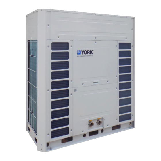
AIR-COOLED MODULAR CHILLER AND HEAT PUMP
Cooke Industries - Phone: +64 9 579 2185
AIR-COOLED MODULAR CHILLER AND
HEAT PUMP
Supersedes: NOTHING
YCAE065/100/130-X
50Hz
R410A
Issue Date:
October 31, 2018
Email: sales@cookeindustries.co.nz
FORM NO.: 6U6H-B01C-NB-EN
Web: www.cookeindustries.co.nz
Advertisement
Table of Contents

Related Manuals for York YCAE065


Summary of Contents for York YCAE065
- Page 1 AIR-COOLED MODULAR CHILLER AND HEAT PUMP INSTALLATION, COMMISSIONING, Supersedes: NOTHING FORM NO.: 6U6H-B01C-NB-EN OPERATION & MAINTENANCE YCAE065/100/130-X AIR-COOLED MODULAR CHILLER AND HEAT PUMP 50Hz R410A Issue Date: October 31, 2018 Cooke Industries - Phone: +64 9 579 2185 Email: sales@cookeindustries.co.nz...
- Page 2 IMPORTANT! READ BEFORE PROCEEDING! GENERAL SAFETY GUIDELINES This equipment is a relatively complicated apparatus. During rigging, installation, operation, maintenance, or service, individuals may be exposed to certain components or conditions including, but not limited to: heavy objects, refrigerants, materials under pressure, rotating components, and both high and low voltage.
- Page 3 Indicates a potentially hazardous situation which will result in possible injuries or damage to equipment if proper care is not taken. Highlights additional information useful to the technician in completing the work being performed properly. External wiring, unless specified as an optional connection in the manufacturer’s product line, is not to be connected inside the control cabinet.
- Page 4 CHANGEABILITY OF THIS DOCUMENT In complying with Johnson Controls’ policy for continuous product improvement, the information contained in this document is subject to change without notice. Johnson Controls makes no commitment to update or provide current information automatically to the manual or product owner. Updated manuals, if applicable, can be obtained by contacting the nearest Johnson Controls Service office or accessing the Johnson Controls website.
- Page 5 BASIC UNIT NOMENCLATURE NAME Y: YORK C: Chiller A: Air-cooled E: Scroll Compressor 5/6/7 Rated Cooling Capacity: 65-65kW; 100-100kW; 130-130kW X: Product Series R: R-Heat Pump M: Modular E: Refrigerant R410A 12/13 50: Power Supply 380V/3N/50Hz Cooke Industries - Phone: +64 9 579 2185 Email: sales@cookeindustries.co.nz...
-
Page 6: Table Of Contents
Contents SECTION 1 – GENERAL INFORMATION AND SAFETY ................ 8 INTRODUCTION ............................8 WARRANTY .............................. 8 SAFETY ..............................9 MISUSE OF EQUIPMENT ........................9 SECTION 2 – PRODUCT DESCRIPTION ....................12 INTRODUCTION ............................ 12 GENERAL SYSTEM DESCRIPTION ....................12 POWER PANEL ............................. 13 ACCESSORIES ............................ - Page 7 INTRODUCTION ............................ 44 BASIC OPERATIONS ........................... 45 ADVANCED OPERATIONS ......................... 45 SECTION 8 – MAINTENANCE ........................48 IMPORTANT ............................48 COMPRESSORS ............................ 48 CONDENSER COILS ..........................48 OPERATING PARAMETERS ......................48 CONDENSER FAN MOTORS ......................48 OVERALL UNIT INSPECTION ......................48 EXPANSION TANK ..........................
-
Page 8: Section 1 - General Information And Safety
SECTION 1 – GENERAL INFORMATION AND SAFETY INTRODUCTION YORK YCAE065/100/130X (18-36 ton, 65-130 kW) chillers and heat pumps are manufactured to the highest design and construction standards to ensure high performance, reliability and adaptability to all types of air conditioning installations. -
Page 9: Safety
• Failure to satisfy any of these conditions will automatically void the warranty. SAFETY YCAE-X units are designed and built within an ISO 9001 accredited design and manufacturing organization. Fluorinated Greenhouse Gases • This equipment contains fluorinated greenhouse gases covered by the Kyoto Protocol. •... - Page 10 The unit is not designed to withstand loads or stresses from adjacent equipment, pipework or structures. Additional components must not be mounted on the unit. Any such extraneous loads may cause structural failure and may result in injury to the operator, or damage to the equipment. General Access There are a number of areas and features, which may be a hazard and potentially cause injury when working on the unit unless suitable safety precautions are taken.
- Page 11 Use of gloves and safety glasses is, however, recommended when working on the unit. The buildup of refrigerant vapor, from a leak for example, does pose a risk of asphyxiation in confined or enclosed spaces and attention should be given to good ventilation. High Temperature and Pressure Cleaning High temperature and pressure cleaning methods (e.g.
-
Page 12: Section 2 - Product Description
SECTION 2 – PRODUCT DESCRIPTION INTRODUCTION YORK Air-Cooled Modular Chiller and Heat Pump provide chilled water or (and) hot water for all air conditioning applications using central station air handling or terminal units. They are completely self- contained and are designed for outdoor (roof or ground level) installation. Each complete packaged... -
Page 13: Power Panel
the job site. The heat exchanger is manufactured in a precisely controlled vacuum-brazing process that allows the filler material to form a brazed joint at every contact point between the plates, creating complex channels. The units with two refrigerant systems use dual circuit BPHEs. Asymmetric channels provide optimal efficiency in the most compact design. -
Page 14: Accessories
Power panel contains: • IPU3 (including I/O board and core board) • Compressor and fan contactors • Compressor thermal relays • Power sequence protector • Power and control wiring terminals • Compressor power terminals Short Circuit Withstand Rating of the unit electrical enclosure shall be (380V: 5,000 Amps). The power wiring is routed through liquid-tight conduit to the compressors and fans. - Page 15 ports: The J12 BAS (RS-485) port, the J7 Equipment (RS-232) port, the J8 Equipment (RS-485) port and the J11 CS port which allows equipment data to be sent to the Johnson Controls Remote Operation Center for remote unit monitoring and diagnostics. Refer to Wiring Diagram for details (Factory-Mounted).
-
Page 16: Section 3 - Handling And Storage
SECTION 3 – HANDLING AND STORAGE Rigging and lifting should only be done by a professional rigger in accordance with a written rigging and lifting plan. The most appropriate rigging and lifting method will depend on job specific factors, such as the rigging equipment available and site needs. -
Page 17: Operating And Storage Conditions
Major damage must be reported immediately to your local Johnson Controls representative. MOVING THE UNIT BY FORKLIFT TRUCKS For models of YCAE065-130, it is recommended that the units are moved by forklift trucks for transit transfer. A wooden pallet is added for forklift use before shipment. -
Page 18: Section 4 - Installation
SECTION 4 – INSTALLATION To ensure warranty coverage, this equipment must be commissioned and serviced by an authorized YORK service mechanic or a qualified service person experienced in unit installation. Installation must comply with all applicable codes, particularly in regard to electrical wiring and other safety elements such as relief valves, HP cutout settings, design working pressures, and ventilation requirements consistent with the amount and type of refrigerant charge. - Page 19 Unit noise is a result of compressor and fan operation. Considerations should be made utilizing noise levels published in the YORK Engineering Guide for the specific unit model. Sound blankets for the compressors and enclosure panels are Cooke Industries - Phone: +64 9 579 2185 Email: sales@cookeindustries.co.nz...
-
Page 20: Isolators (Optional)
available as options. Cold Climate Locations If the unit is operating in low ambient temperature, be sure to follow the instructions listed below. 1. A baffle plate installed on the airside of the unit is recommended to prevent exposure to snow in winter. - Page 21 Piping to the inlet and outlet connections of the unit should include high-pressure rubber hose or piping loops to ensure against transmission of water pump vibration. The necessary components must be obtained in the field. Drain connections should be provided at all low points to permit complete drainage of the cooler and system water piping.
-
Page 22: Pipework Arrangement
2. Site restrictions may compromise minimum clearances indicated below, resulting in unpredictable air flow patterns and possible diminished performance. York's unit controls will optimize operation without nuisance high pressure safety cutout; however, the system designer must consider potential performance degradation. -
Page 23: Wiring
evaporator. 6. Stop valves must be installed at the inlet of each unit to balance chilled liquid distribution. 7. A minimum interval must be reserved for field wiring, commissioning and maintenance. 8. Refer to single unit drawings for detailed dimensions. WIRING The units are shipped with all factory-mounted controls wired for operation. - Page 24 the system is functioning normally. The respective contacts will close when the unit is shut down on a unit fault, or locked out on a system fault. For modular applications, the master unit will not only output internal fault, but also the fault of subordinate units. Field connections are at XTB2 terminals 23 to 24.
- Page 25 The SC-EQ (Smart Chiller Equipment) Communication Card is an economical and versatile communications device that provides a communication connection between the unit and standard open BAS protocols. It efficiently manages all of the communication protocols used by York equipment, exposing the data in a consistent, organized, and defined fashion.
-
Page 26: Power Supply Connection
POWER SUPPLY CONNECTION Electrical Legends ABBREVIATIONS OF ELECTRICAL COMPONENTS – YCAE065X ABBREVIATIONS OF ELECTRICAL COMPONENTS – YCAE100/130X Cooke Industries - Phone: +64 9 579 2185 Email: sales@cookeindustries.co.nz Web: www.cookeindustries.co.nz... - Page 27 Power Supply Connection – Single Unit Power Supply Connection – Modular Cooke Industries - Phone: +64 9 579 2185 Email: sales@cookeindustries.co.nz Web: www.cookeindustries.co.nz...
-
Page 28: Control Wiring
Notes 1. Power wiring must be provided through a protect device (fused disconnect switch or circuit breaker) to the input terminals of the unit in accordance with CE or local code requirements. 2. Every control board is assigned with one ID address. If a single module includes two control boards, then two ID addresses have to be assigned in the module. - Page 29 COMMUNICATION CABLE REQUIREMENT Notes 1. The total length of the communication cable L=L1+L2+L3...+Ln. The communication cable should be shielded twisted in pairs. Refer to the table above for cable requirement. 2. Every control board is assigned one ID address. 3. The maximum quantity of the control boards in the same communication network should be 32, and different control boards should use different ID addresses.
- Page 30 YCAE100/130X Notes 1. External interlock is short-circuited or is linked to external facilities before operation; 2. Water pump control is connected by factory before delivery if hydro kit is selected; 3. 45-130 models: SF1 (DI12/XTB2:80K&93) -- Factory installation; SF2 (DI5/XTB2:80E&85) -- Short-circuited before delivery;...
-
Page 31: Section 5 - Technical Data
SECTION 5 – TECHNICAL DATA PHYSICAL DATA Model YCAE065X YCAE100X YCAE130X Rated Cooling Capacity 65.0 100.0 130.0 Rated Heating Capacity 66.0 100.7 131.9 Refrigerant Charge 12.5 8.3+11.5 11.5×2 Cooling 20.4 29.2 39.3 Rated Power Input Heating 20.0 31.0 42.8 Cooling Rated Current Heating Type... -
Page 32: Electrical Data
ELECTRICAL DATA Model YCAE065X YCAE100X YCAE130X Power Supply 380V 3N~ 50Hz 380V 3N~ 50Hz 380V 3N~ 50Hz Voltage Range 342V~418V 342V~418V 342V~418V 112A Breaker 63A 4P 100A 3P 160A 3P Power Cable 10 mm 25 mm 35 mm Notes 1. Above specifications of wirings and circuit breakers are based on 40℃ ambient temperature. Please refer to local rules for details. - Page 33 Cooke Industries - Phone: +64 9 579 2185 Email: sales@cookeindustries.co.nz Web: www.cookeindustries.co.nz...
- Page 34 YCAE100/130X Cooke Industries - Phone: +64 9 579 2185 Email: sales@cookeindustries.co.nz Web: www.cookeindustries.co.nz...
- Page 35 Cooke Industries - Phone: +64 9 579 2185 Email: sales@cookeindustries.co.nz Web: www.cookeindustries.co.nz...
-
Page 36: Dip Switch Setting
DIP SWITCH SETTING Microboard DIP Switch Two DIP switches, SW301 and SW302, are located on the IPU3 micro board. SW301 is an eight-digit switch and the first five digits are used to set communication addresses for each module. It is converted from decimalism to binary. - Page 37 Model and Function Setting The last 3 digits of SW301 are used to set models. Model SW301-6 SW301-7 SW301-8 The digits of SW302 are used to set the configurations of the unit. This is already finished before unit delivery. SW302-1 SW302-2 SW302-3 Only available for 1# unit...
-
Page 38: Dimensions
DIMENSIONS YCAE065X YCAE100/130X All dimensions are in mm unless specified otherwise. The enclosure panels of YCAE100/130X as shown are optional. Cooke Industries - Phone: +64 9 579 2185 Email: sales@cookeindustries.co.nz Web: www.cookeindustries.co.nz... -
Page 39: Clearances
2. Site restrictions may compromise minimum clearances indicated below, resulting in unpredictable airflow patterns and possible diminished performance. 3. YORK’s unit controls will optimize operation without nuisance high-pressure safety cutouts; however, the system designer must consider potential performance degradation. CLEARANCES... -
Page 40: Section 6 - Commissioning
SECTION 6 – COMMISSIONING COMMISSIONING Commissioning of this unit should only be carried out by YORK Authorized personnel. Commissioning personnel should be thoroughly familiar with the information contained in this literature, in addition to this section. Perform the commissioning using the detailed checks outlined in the START-UP CHECK LIST as the commissioning procedure is carried out. -
Page 41: Preparation - Power On
To add oil to a circuit – connect a YORK hand oil pump to the 1/4” oil charging connection before the accumulator with a length of clean hose or copper line, but do not tighten the flare nut. Using clean oil of the correct type, pump oil until all air has been purged from the hose then tighten the nut. -
Page 42: Unit Operating Sequence
outside of these limits is undesirable and could cause damage. If mains power must be switched OFF for extended maintenance or an extended shutdown period, the compressor suction and discharge service stop valves should be closed (clockwise). If there is a possibility of liquid freezing due to low ambient temperatures, the coolers should be drained or power should be applied to the unit. - Page 43 5. The corresponding condenser fan will be cycled on when compressor starts. 6. Each system is fitted with an EEV (electrical expansion valve) in the liquid line between condenser coil and cooler. The device will automatically adjust the steps to satisfy refrigerant flow demand, based on the difference between actual and target superheat.
-
Page 44: Section 7 - Wire Controller Operation
SECTION 7 – WIRE CONTROLLER OPERATION Don’t touch the screen with sharp points or edges which may damage the controller. Don’t twist or pull the wires of the controller. Don’t wipe the controller with benzene, diluent or chemical cloth. Otherwise discoloration or mechanical failure may occur. -
Page 45: Basic Operations
BASIC OPERATIONS Start and Stop the Unit Press the button below the screen to start or stop the unit. Operating Mode Press the key of “COOLING” or “HEATING” to set or switch operating modes. The “SET” icon will be showing during the process. Press “CONFIRM” to finish the setting, or the controller will autosave if there’s no operation for 10 seconds. - Page 46 Press “TIMER” to toggle between Year, Month, Day, Hour and Minute. Press “UP” and “DOWN” icons to modify the values. Touch and hold the icons to increase or decrease the values by 5 each time. Press “CONFIRM” to save the value and auto switch to the next setting. Press “TIMER” to cancel the operation and auto switch to the next setting.
- Page 47 Press “UP” and “DOWN” for more fault information. A maximum of 16 faults can be recorded. The setting will terminate if there’s no operation for 5 seconds or “CANCEL” is pressed. Running Status Press “FUNCTION” and “CONFIRM” keys for 5 seconds to enter Running Status viewing screen. The digital and analog inputs and outputs are displayed in sequence in hour display area (Area 1) by pressing “UP”...
-
Page 48: Section 8 - Maintenance
The following is intended only as a guide and covers only the unit components. It does not cover other related system components which may or may not be furnished by YORK. maintained... -
Page 49: Expansion Tank
immediately. EXPANSION TANK Unless otherwise stated, at least once every year the expansion tank must be checked to verify that the pre-charge is within the value indicated on the label with a tolerance of ± 20%. Cooke Industries - Phone: +64 9 579 2185 Email: sales@cookeindustries.co.nz Web: www.cookeindustries.co.nz... -
Page 50: Modbus Protocol
ModBus Protocol DEFINITIONS ITEM DESCRIPTION Communication Baud rate: 9600bps; 8-N-1: 1 start bit,1 stop bit, check bit-none, 8 data bits; Data Flow Modbus-RTU Protocol; CRC: Cyclic Redundancy Check; Hexadecimal data. Modbus as master; Master - Slave 1# microboard as slave. Unit: 0.1 °... - Page 51 SYSTEM SETPOINTS Short Name Register Function Code Note (BACnet Object Name) Address System Setpoints Chiller ON/OFF 3, 6, 16 0-Invalid, 1-On, 2-Off 0-Cooling, 1-Heating, 8-Pump Mode Setting 3, 6, 16 Circulation Cool RT Setpoint 3, 6, 16 -7~25 Heat RT Setpoint 3, 6, 16 15~50 Cool LT Setpoint...
- Page 52 SYSTEM PARAMETERS Short Name Register Function Code Note (BACnet Object Name) Address System Setpoints Chiller ON/OFF 0-OFF, 1-ON System Status 0-Cooling、1-Heating、8-Pump bit0: 1-Antifreezing bit1: 1-Defrost Other status bit2: 1-Low Sound Mode bit3: Pump Status, 1-On, 0-Off Bit4: Compressor Status, 1-On, 0-Off HMI Communication status 1-ON, 0-OFF Unit Networks status...
- Page 53 UNIT PARAMETERS Short Name Register Function Code Note (BACnet Object Name) Address Unit Software Versions A 1000-1009 AI1-32 1021-1052 Chiller EWT 1021 Ambient Temp 1022 Ckt1 Coil Temp 1023 Ckt2 Coil Temp 1024 Unit LWT 1025 Chiller LWT 1026 Ckt1 Suct Temp 1027 Ckt2 Suct Temp 1028...
- Page 54 UNIT PARAMETERS (CONT’D) Short Name Register Function Code Note (BACnet Object Name) Address EVA heater bit4: 1-ON, 1-OFF Ckt1 oil heater bit5: 1-ON, 1-OFF Fault Output bit6: 1-ON, 1-OFF Chiller Pump bit7: 1-ON, 1-OFF Water Heater bit8: 1-ON, 1-OFF VSD fan bit9: 1-ON, 1-OFF Ckt2 Fan Motor bit10: 1-ON, 1-OFF...
- Page 55 FAULT DEFINITIONS Fault Fault Address Note Class (BACnet Object Name) Code Chiller EWT sensor fault ★ Bit0 Bit0: 1-Fault System Ambient temp sensor fault ★ Bit1 Bit1: 1-Fault System Bit2 Ckt1 Coil temp sensor fault Bit2: 1-Fault Unit Bit3 Ckt2 Coil temp sensor fault Bit3: 1-Fault Unit Bit4...
- Page 56 FAULT DEFINITIONS (CONT’D) Fault Fault Address Note Class (BACnet Object Name) Code Bit0 Ckt1 Fan fault Bit0: 1-Fault Unit Bit1 Ckt2 Fan fault Bit1: 1-Fault Unit Bit2 Ckt1 HPS fault/ Comp 1 or 2 overload fault Bit2: 1-Fault Unit Bit3 Ckt1 LPS fault Bit3: 1-Fault Unit...
- Page 57 FAULT DEFINITIONS (CONT’D) Fault Fault Address Note Class (BACnet Object Name) Code Bit0 Comm. Failure (Slave unit with master) Bit0: 1-Fault Unit Bit1 Chiller Dial Switch setting error Bit1: 1-Fault Bit2 Time limit protection Bit2: 1-Fault System Bit3 Low ambient temperature in cooling Bit3: 1-Fault System Bit4...
- Page 58 FAULT DEFINITIONS (CONT’D) Fault Fault Address Note Class (BACnet Object Name) Code Bit0 Unit Dial Switch setting error Bit0: 1-Fault Unit Bit1 Comm failure( unit with driver) Bit1: 1-Fault Unit Bit2 Comm failure( unit with fan 1) Bit2: 1-Fault Unit Bit3 Comm failure( unit with fan 2) Bit3: 1-Fault...
-
Page 59: Pressure Transducer Diagram
PRESSURE TRANSDUCER DIAGRAM Low Pressure Transducer High Pressure Transducer Cooke Industries - Phone: +64 9 579 2185 Email: sales@cookeindustries.co.nz Web: www.cookeindustries.co.nz... -
Page 60: R410A Pressure Temperature Chart
R410A PRESSURE TEMPERATURE CHART Gauge Gauge Temperature Transducer Temperature Transducer Pressure Pressure ° C Output ° C Output -400 -390 -380 -370 -360 -350 -340 -330 -320 -310 1010 -300 1050 -290 1080 -280 1120 -270 1150 -260 1190 -250 1220 -240 1260... - Page 61 R410A PRESSURE TEMPERATURE CHART (CONT’D) Gauge Pressure Temperature Transducer ° C Output 2570 2640 2700 2770 2840 2910 2980 3050 3120 3200 3270 3350 3430 3510 3590 3670 3750 3840 3920 4010 4100 4190 4280 4370 4470 4560 4600 Cooke Industries - Phone: +64 9 579 2185 Email: sales@cookeindustries.co.nz Web: www.cookeindustries.co.nz...
- Page 62 YORK Guangzhou Air Conditioning & Refrigeration Co., Ltd. Phone: +86 763 4681111 Fax: +86 763 4681111 FORM NO.: 6U6H-B01C-NB-EN © 2018 Johnson Controls, Inc. www.johnsoncontrols.com SUPERSEDES: NOTHING Johnson Controls is committed to the continuous product improvement. Please note the product design may change without notification.