Vaillant aroSTOR VWL B 200/5 UK Installation And Maintenance Instructions Manual
Hide thumbs
Also See for aroSTOR VWL B 200/5 UK:
- Operating instructions manual (24 pages) ,
- Installation and maintenance instructions manual (32 pages)

Related Manuals for Vaillant aroSTOR VWL B 200/5 UK


Summary of Contents for Vaillant aroSTOR VWL B 200/5 UK
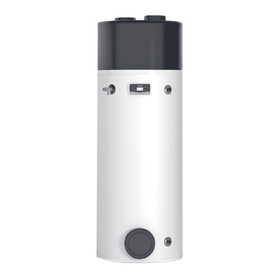
- Page 1 aroSTOR VWL B 200/5 UK VWL B 270/5 UK en Installation and maintenance instructions...
-
Page 2: Table Of Contents
Installation and maintenance Resetting the safety cut-out ......... 21 Replacing the mains connection cable ....22 instructions Completing repair work........22 Contents Inspection and maintenance ......22 10.1 Preparing the maintenance and repair work..22 10.2 Observing inspection and maintenance Safety .............. -
Page 3: Safety
Safety General safety information 1.3.1 Risk caused by inadequate Action-related warnings qualifications Classification of action-related warnings The following work must only be carried out The action-related warnings are classified in by competent persons who are sufficiently accordance with the severity of the possible qualified to do so: danger using the following warning symbols –... - Page 4 ▶ Wear suitable personal protective equip- 1.3.4 Risk of death due to lack of safety devices ment and bring a fire extinguisher with you. ▶ Only use tools and units that are permit- The basic diagrams included in this docu- ted for R290 refrigerant and are in proper ment do not show all safety devices required working condition.
-
Page 5: Regulations (Directives, Laws, Standards)
1.3.11 Risk of material damage caused by 1.3.15 Structural damage due to escaping frost water ▶ Do not install the product in rooms prone Escaping water can cause damage to the to frost. building. ▶ Install the hydraulic lines without tension. 1.3.12 Risk of material damage caused by ▶... -
Page 6: Notes On The Documentation
Pass these instructions and all other applicable docu- ments on to the end user. Validity of the instructions These instructions apply only to: Unit – article number aroSTOR VWL B 200/5 UK 0010024440 aroSTOR VWL B 270/5 UK 0010028218 Kit, unvented tank 18L HP Vaillant... -
Page 7: Basic System Diagram
Basic system diagram Domestic hot water cylinder Air inlet temperature sensor Heating coil Evaporator Immersion heater temperature cut-out Defrosting sensor Immersion heater safety cut-out Thermostatic expansion valve External condenser Thermostatic expansion valve capillary Domestic hot water cylinder temperature sensor Defrosting valve Compressor Drainage filter Pressure switch... -
Page 8: Type Designation And Serial Number
The declaration of conformity can be viewed at the manufac- turer's site. Hot Water Association Vaillant is a full member of the Hot Water Association and promotes the scheme in association with its cylinder range. Details are available on the web site www.vaillant.co.uk Caution. -
Page 9: Unpacking The Product
Ensure that no-one leans against the product or knocks Checking the scope of delivery Unit dimensions and connection dimensions aroSTOR VWL B 200/5 UK aroSTOR VWL B 270/5 UK 634 mm 634 mm 158 mm... -
Page 10: Removing/Installing The Protective Cover
▶ In order to avoid noise disturbance, do not install the Danger! product near bedrooms. Risk of scalding and/or damage due to ▶ We recommend maintaining a clearance of at least incorrect installation leading to escaping 300 mm above and below the unit to allow the upper water. - Page 11 ▶ In order to prevent leak air from being extracted by recir- Maximum length of the air pipes L1 + L2 (L1 = air in- culation, maintain a clearance between the ends of the take pipe; L2 = air outlet pipe) air pipes.
-
Page 12: Installing The Water Connections
– Air flow: ≥ 400 m³/h ▶ Add to the withdrawn air flow the flow rate that is required for normal ventilation of the installation room. ▶ If required, adjust the ventilation. Without the pipe system External area Ventilation Internal area (heated or not heated) Partial pipe system Installing the water connections... - Page 13 – Minimum diameter of the copper pipe: ≥ 22 mm Connect the domestic hot water flow to (2). – Minimum diameter of the copper pipe: ≥ 22 mm Carry out a leak-tightness check on all connections, including the expansion relief valve (3). 5.2.4 Installing the drain valve The drain valve must be supplied by the customer.
- Page 14 Size of the Length of the pipe Pre-charge pres- cylinder that has a diameter sure of the expan- of 22 mm sion vessel 900 mm 0.3 MPa (3.0 bar) 1,200 mm 0.3 MPa (3.0 bar) Install a pipe between the safety assembly's connec- tion and the temperature and pressure relief valve.
- Page 15 Size of Minimum Minimum Maximum Resist- the outlet diameter diameter permiss- ance per valve of the of the dis- ible res- elbow or discharge charge istance, bend pipe D1 pipe from inform- the tun- ation dish D2 on the length of ≥...
-
Page 16: Electrical Installation
Electrical installation 5.3.3 Connecting the cable for low-tariff or high- tariff load relief Only qualified electricians are allowed to carry out the elec- trical installation. Note The PV function and the management outside of Danger! the power consumption cannot be used in parallel Risk of death from electric shock! as they use the same contact. -
Page 17: Start-Up
5.3.4 Controlling the fan externally Caution. Risk of material damage caused by incor- Condition: Installing a partial pipe system rect handling. Only external control contacts are compat- ible. T air ▶ Only connect the external control contacts T degiv to potential-free contacts. T eau ▶... -
Page 18: Filling The Domestic Hot Water Circuit
switch-on time corresponds to the heat-up time and ments of the water regulations for supplying hygienically safe potable water. heating is permitted by the electricity tariff. ◁ When the heat pump is running, there is an air flow If required, precautions can be taken to minimise the effects at the air inlet and outlet. -
Page 19: Reading The Input Data
– Factory setting: 60 ℃ Press the menu button to return to the original display. ◁ PV MAX = High level of photovoltaic power genera- Setting the anti-legionella function tion. The heat pump and the immersion heater gen- erate an increased domestic hot water temperature. Danger! The increased domestic hot water temperature must be between the domestic hot water temperature of... -
Page 20: Setting The Minimum Temperature
on and the higher the energy consumption and Note consequently the energy costs as a result. When using a low-tariff connection, you should not set any additional time-programming. Note The amount of power available depends ▶ Press the menu button to return to the original display. on the load relief level and the time period ▶... -
Page 21: Checking The Immersion Heater
8.10.3 Manually locking the operator control Remove the black decorative panel by pulling it force- fully to the side. elements Undo the screws (2) on the lower covering hood (3). In the basic display, hold down the menu button and Remove the lower covering hood (3). -
Page 22: Replacing The Mains Connection Cable
10.2 Observing inspection and maintenance Note intervals The safety cut-out settings must not be ▶ changed. Adhere to the minimum inspection and maintenance in- tervals. Annual inspection and maintenance work – Overview Replacing the mains connection cable 10.3 Draining the product Decommission the product. -
Page 23: Checking The Inside Of The Cylinder
13 Recycling and disposal Disposing of the packaging ▶ Dispose of the packaging correctly. ▶ Observe all relevant regulations. ▶ For detailed information refer to www.vaillant.co.uk. 0020285063_05 Installation and maintenance instructions... -
Page 24: Appendix
Appendix Annual inspection and maintenance work – Overview Work Check the connections for tightness. Check the temperature and pressure expansion relief valve. Check the expansion relief valve. Check the pressure in the expansion vessel. Check the domestic hot water output at the valve (if required, clean the filters). Check that the safety devices are functioning properly. - Page 25 Fault code Description Possible cause Solution Temporary operation – – CLOC K Time Overvoltage in the Replacing the display Operating times are no power grid longer considered: – – Damage during trans- Replacing the display Target temperature for do- port connection cable mestic hot water is per- manently maintained (no...
- Page 26 Fault code Description Possible cause Solution Temporary operation – Incorrect temperature The air temperature Connecting the temper- sensor readings sensor and the defrost- ature sensors to the PCB ing sensor have been correctly inverted on the PCB – The defrosting sensor and the water temper- ature sensor have been inverted on the PCB...
-
Page 27: C Installer Level - Overview
Installer level – Overview Setting level Values Factory Unit Increment, select, explanation setting Min. Max. INST.MENU → PV MODE → PV MODE Current value YES, no INST.MENU → PV MODE → PRIORITY PRIORITY Current value YES: PV MODE has higher priority than frost protection and eco mode;... -
Page 28: D Electronics Box Wiring Diagram
Electronics box wiring diagram T air T degiv T eau Comp Alim Ph 4 Ph 5 Ph 12 N 13 Control panel Pressure switch Control panel connection plug Safety cut-out, 87 °C Main PCB Immersion heater Connection plug no. 1: Low tariff or lower level of 230 V power supply electrical energy generated by the photovoltaic 20 µF condenser... -
Page 29: E Heat Pump Output Curves
Heat pump output curves 00:00 21:00 18:00 15:00 12:00 09:00 6:00 3:00 00:00 Air temperature in °C Heating time at a water temperature of 10 °C for a target temperature of 55 °C Working figure (COP) (EN 16147:2017/extraction cycle L) COP at a cold water temperature of 10 °C for a tar- get temperature of 55 °C (EN 16147:2017/extraction cycle L) -
Page 30: G Technical Data
Technical data Technical data – General aroSTOR VWL B 200/5 UK aroSTOR VWL B 270/5 UK Nominal capacity 197.5 l 269 l Outer diameter 634 mm 634 mm Height 1,458 mm 1,783 mm Weight (when empty) 55 kg 68 kg... - Page 31 VWL B 200/5 UK aroSTOR VWL B 270/5 UK Sound power level LWA (V1) 50/52 dB 50/52 dB Nominal heat output of the heat pump (water temperat- 700 W 700 W ure: 55 °C) Nominal heat output of the heat pump (water temperat-...
-
Page 32: Index
Index Voltage .................. 3 Basic diagram................ 4 Water hardness ..............5 Wiring .................. 16 Calling up the installer level..........18 CE marking................8 Checking the pre-charge pressure of the expansion vessel .................. 22 Combustion air ..............5 Competent person..............3 Completing repair work ............ - Page 36 Supplier Vaillant Ltd. Nottingham Road Belper Derbyshire DE56 1JT Telephone 0330 100 3143 info@vaillant.co.uk www.vaillant.co.uk 0020285063_05 Publisher/manufacturer Vaillant GmbH Berghauser Str. 40 D-42859 Remscheid Tel. +49 2191 18 0 Fax +49 2191 18 2810 info@vaillant.de www.vaillant.de © These instructions, or parts thereof, are protected by copyright and may be reproduced or distributed only with the manufacturer's written consent.