
Related Manuals for Vaillant auroSTEP plus VIH SN 350/3 MiP


Summary of Contents for Vaillant auroSTEP plus VIH SN 350/3 MiP
- Page 1 For the heating engineer System Description, Installation and Maintenance Manual auroSTEP plus System for solar powered hot water generation VIH SN 350/3 MiP VIH SN 350/3 iP VEH SN 350/3 iP VEH SN 350/3 iP-c...
-
Page 3: Table Of Contents
For the heating engineer System description auroSTEP plus Contents Notes on the documentation ......2 Storage of the documents ........2 Symbols used ............2 Applicability of the manual ........2 System description ........2 Scope of delivery and accessories ....2 Cylinder unit .............5 Construction and function ........5 System description auroSTEP plus 0020077748_FT1... -
Page 4: Scope Of Delivery And Accessories
1 Notes on the documentation 2 System description Notes on the documentation Applicability of the manual This system description applies exclusively to units with The following notes are intended to help you throughout the following part numbers: the entire documentation. Further documents apply in connection with this system Appliance type Part number... -
Page 5: Cylinder Unit
System description 2 Fig. 2.1 Scope of delivery and accessories for the auroSTEP system Accessories for on-roof mounting: 17 Mounting rail Key: 18 Rafter anchor type P for Frankfurt pantiles Scope of delivery: 19 Rafter anchor type S for plain tiles or slates Collector - auroTHERM classic VFK 135 D (2 ea.) 20 Hanger bolt mounting kit 2 Single tube insulation, bird-safe, 0.75 m long... - Page 6 2 System description Item Description Qty.(kit) Part number (kit) No. of kits (system) Frame with clamping element 0020059885 Mounting rail (2 ea./collector) 0020059900 Gravel tray (optional) 0020059905 (3 ea.) Safety clamps Table 2.3 System material list for flat roof installation Item Description Qty.(kit) Part number (kit)
-
Page 7: Construction And Function
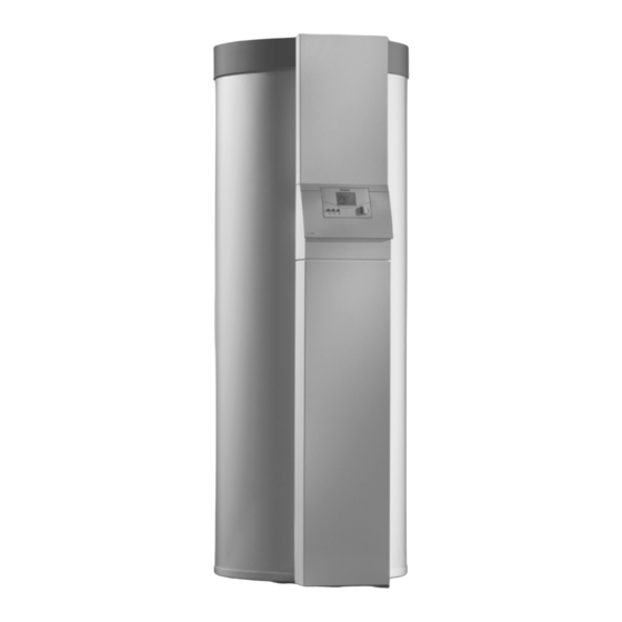
Cylinder unit Construction and function The auroSTEP plus solar energy system is used for solar The Vaillant auroSTEP plus solar energy system is a assisted hot water generation. Most of the components thermal solar energy system for generating hot water. - Page 8 DIN 1988, use only copper piping with an internal diameter of 8.4 mm for piping the system. Vaillant recommends the easy to install "2 in 1 solar copper pipe", available as an accessory in 10 m lengths (Part No. 302359) or in 20 m lengths (Part No.
- Page 9 Packaging ............... 29 4.4.4 Transport without insulation .......11 4.4.5 Fitting the insulation and the casing ....12 Customer service and guarantee....29 11.1 Vaillant customer service ........29 Installation ............. 12 11.2 Manufacturer's guarantee ......... 29 Fitting the DHW supply lines .......12 Fitting the solar connections ......12...
-
Page 10: Notes On The Documentation
Danger! technology. Immediate risk of serious injury or death! The Vaillant auroSTEP plus solar energy system is a state-of-the-art appliance which has been constructed in Danger! accordance with recognised safety regulations. -
Page 11: Safety Instructions And Regulations 3
Make absolutely sure you wear anti-fall devices whenev- We only honour the manufacturer’s warranty if the in- er there is a risk of falling. (We recommend the Vaillant stallation is performed by an approved qualified servic- safety belt, Part No. 302066.) Observe the accident pre- ing company. -
Page 12: Safety Data Sheet For Solar Fluid
Substance/Formulation and company name 6.2 Environmental measures: 1.1 Information on the product: Contaminated water/ fire water may not be dis- Brand name Vaillant Solar Fluid, ready mixed charged into watercourses without pre-treatment 1.2 Information on the supplier: (biological sewage plant). - Page 13 Safety instructions and regulations 3 8. Limitation of exposure and personal protective 10. Stability and reactivity equipment 10.1 Substances to be avoided: 8.1 Personal protective gear: Strong oxidants Breathing protection: 10.2 Dangerous reactions: Breathing protection in the event of a release of va- No dangerous reactions if the storage and handling pours/aerosols regulations/notes are observed...
-
Page 14: Regulations
Part 2–4: Actions on structures - Wind loads 17. Status: Created on 01. 02. 2008 Cylinder and cylinder installation by: Vaillant GmbH. Pressure equipment directive 97/23/EC Regulations Directive of the European Parliament and Council from In particular, the relevant version of the following laws,... -
Page 15: Regulations For Germany
Safety instructions and regulations 3 Lightning protection Cylinder and cylinder installation ENV 61024-1 Pressure equipment directive 97/23/EC Protection of structures against lightning – Part 1: Gen- Directive of the European Parliament and Council from eral principles (IEC 1024-1: 1990; modified) 29th May, 1997 for the approximation of the laws on pressure equipment of the Member States 3.2.2 Regulations for Germany... -
Page 16: Assembly
4 Assembly Assembly Note! As with all equipment for generating and Installation location providing hot water, noises also arise in this solar energy system at a level which is Solar cylinder unit certainly in general below that of today's • To prevent heat losses, please install the solar cylin- conventional combustion boilers;... -
Page 17: Appliance And Connection Dimensions
Assembly 4 Appliance and connection dimensions Fig. 4.2 Appliance and connection dimensions of the solar cyl- inder unit Hot water connection R 3/4 R = external thread 2 Cylinder flow R 1 3 Cylinder return R 1 4.3.1 Installing the collectors 4 Cold water connection R 3/4 Install the collectors. -
Page 18: Transport To The Installation Location
4 Assembly Transport to the installation location 4.4.2 Transport without packaging The cylinder is delivered fully assembled. You have various options for transport to the installa- tion site. – Complete in the packaging, if possible at the customer side – Without packaging, completely assembled, if the transport route permits it –... -
Page 19: Transport Without Insulation
Assembly 4 • Remove the top cap (1) from the cylinder. • Pull the two covers (2) and (3) off the front of the cyl- inder. Fig. 4.7 Fastening the casing jacket with the clip 4.4.4 Transport without insulation Fig. 4.6 Releasing the casing jacket •... -
Page 20: Fitting The Insulation And The Casing
– Service valves – Legionella protection pump, as required Caution! Vaillant can only guarantee the function of the There is an accessory kit (Part No. 305 967) available solar energy system if 2 in 1 solar copper pipe for the installation of pipes by the customer which con- of 10 m in length (Part No. - Page 21 • Remove the upper and lower casing from the front • Run the Vaillant 2 in 1 solar copper pipe from the roof of the cylinder unit by pulling them away from the to the installation location for the cylinder unit. Please retaining clips.
-
Page 22: Electrical Installation
5 Installation Electrical installation 5.3.1 Regulations The regulations of VDE and EVU must be observed dur- ing the electrical installation. Use standard wires for wiring. Cross-sections of the cables: – 230 V supply cable (mains cable): 2.5 mm – Low voltage cables (sensor cables): at least 0.75 mm Sensor cables must be no longer than 50 m. - Page 23 Installation 5 Danger! Caution! Danger of damaging the PCB due to overload Risk of damaging electric wiring! The C1/C2 contact is a 24 V low-voltage con- Due to the high temperatures, the electric tact and may not under any circumstances be wiring may not touch any components carrying used as a 230 V switching contact.
- Page 24 5 Installation Kol1 C1/C2 C1/C2 C1/C2 230 V Kol2-P Kol1-P Fig. 5.8 Hydraulic plan 2 Designation in Component hydraulic plan/ wiring diagram I, II, III Option for connecting to different heaters for reheating the cylinder C1/C2 Connections for controlling the heating appli- ances for reheating the cylinder Cold water HZ-K...
-
Page 25: Start-Up 6
Installation 5 Start-up 6 VC / VK 230V Netz Kol 2-P Kol 1-P LEG/BYP * EP * VRS 550 C1 /C2 Kol 1 Sp 1 Sp 2 * An anti-Legionella pump can be connected to the LEG/BYP terminals (accessory). A contactor for an electric heating element can be controlled via the EP terminals (accessory). -
Page 26: Setting System Parameters
6 Start-up Setting system parameters Caution! Risk of damaging the collector pump During initial start-up, switch off the collector pump immediately after switching on the power supply by turning the controller to the mode. After setting the system parameters, you must vent the solar energy system (see Section 6.4). - Page 27 Start-up 6 Display Setting by turning the knob Setting range Default setting Activation of anti-Legionella programme. 0 [Off], 1 [Day] (not relevant for 0 [Off] the PROMOTELEC version), 2 [Night] Setting of filling mode duration 3 - 9 min 9 min Determines whether booster pump is con- 0 [not connected], 1 [connect- nected...
-
Page 28: Equalising The Pressure In The Solar Heating System
6 Start-up Note! • Do not immerse the end of the hose in the solar fluid, You can reset the system parameters and the to protect yourself from any escaping hot vapour or timer programmes back to the default settings solar fluid. -
Page 29: Checking The Solar Heating System For Leaks
• Cover all exposed solar lines and the compression fit- tings, including those on the roof, with appropriate in- sulation material after the leak test. For this, Vaillant recommends the bird-safe individual pipe insulation with polyamide protective braid, 2 x 75 cm long (Part No. - Page 30 6 Start-up Start-up record The solar system of: has been started up, while taking the following points into consideration: 1. INSTALLATION O.K. Remarks Anchor secured according to regulations Solar line cabled with equipotential bonding Roof covering reapplied as prescribed after positioning the anchors Roof membrane not damaged Collectors' sheet covering removed Blow-off line installed at the expansion relief valve in the solar circuit...
- Page 31 Start-up 6 3. CONTROL SYSTEMS O.K. Remarks Temperature sensors indicate plausible values Check that solar pump is running and circulating Solar circuit becomes warm In full sunshine the temperature difference between flow and return is a max. of 14 °C Boiler post-heating starts at: °C Circulation pump running time from...
-
Page 32: Maintenance
• Switch off the power supply and drain the cylinder. Collectors All Vaillant GmbH solar collectors comply with the re- quirements of the German "Blue Angel" environmental label. In this respect we, as the manufacturer, are committed to take back and recycle components when they have to be disposed of after years of reliable service. -
Page 33: Servicing The Magnesium Protection Anode
Maintenance 8 • Release the screws (2) and remove the flange cover Servicing the magnesium protection anode (1). The cylinders are equipped with a magnesium protec- tion anode which has to be checked the first time after Cleaning the tank two years and then regularly once a year. -
Page 34: Checking The Expansion Relief Valve
The solar fluid must be changed every three years. Note! Caution! When filling with new solar fluid, establish a Vaillant only assumes liability for the function blow-off line from the solar expansion relief of the solar energy system if it is filled with valve to the collecting container. -
Page 35: Collectors
Maintenance 8 • Now carefully pour approx. 10.5 l of Vaillant solar fluid Recommended maintenance checklist (Part No. 302 363) into the funnel until the fluid can Maintenance work on the Maintenance interval be seen in the sight glass (1). - Page 36 9 Service/diagnostics 9 Service/diagnostics You can access the service/diagnostic level by simulta- neously pressing the programming button and the knob for approx. 3 seconds. Display Actuators/Sensor values Test procedure Test collector pump 1 (solar pump) Collector pump 1 on, all other actuators off Test collector pump 2 (booster pump) Collector pump 2 on, all other actuators off Test anti-Legionella pump / Bypass-diverter valve...
-
Page 37: Recycling And Disposal 10
100 l. 10.4 Packaging Vaillant has reduced the transport packaging of the ap- pliances to a minimum. The strict selection of packaging Fig. 9.1 Checking the visual display materials is based on their recyclability. -
Page 38: Technical Data
12 Technical data 12 Technical data 12.1 Cylinder unit VIH SN 350i Units VIH SN 350i Cylinder capacity Hot water output l/10min Permissible operating overpressure Operating voltage V AC/Hz 230/50 Power consumption max. 180 Contact load of the output relays (max.) Shortest switching interval Power reserve Maximum ambient temperature... -
Page 39: Sensor Characteristics
Technical data 12 12.2 Sensor characteristics 12.3 Flat collector VFK 135 D Units VFK 135 D Cylinder sensors Sp1 and Sp2, Type NTC 2.7 K Absorber type Serpentine horizontal Dimensions (L x W x H) 1233 x 2033 x 80 Sensor characteristic Resistance value Weight...