Table of Contents
Advertisement
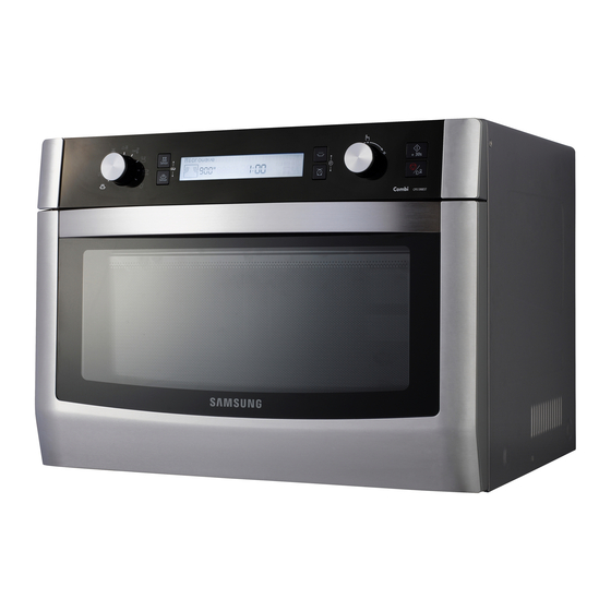
MICROWAVE OVEN
Refer to the service manual in the GSPN(see rear cover) for the more information.
MICROWAVE OVEN
BASIC:
CP1395EST
MODEL:
CP1395E-S
MODEL CODE: CP1395E-S/XET
CONTENTS
1. Precaution
2. Product Specification
3. Disassembly and Reassembly
4. Troubleshooting
5. Exploded Views and Part List
6. PCB Diagrams
7. Wiring Diagrams
8. Schematic Diagrams
Advertisement
Table of Contents

Related Manuals for Samsung CP1395E-S


Summary of Contents for Samsung CP1395E-S
- Page 1 MICROWAVE OVEN BASIC: CP1395EST MODEL: CP1395E-S MODEL CODE: CP1395E-S/XET MICROWAVE OVEN CONTENTS 1. Precaution 2. Product Specification 3. Disassembly and Reassembly 4. Troubleshooting 5. Exploded Views and Part List 6. PCB Diagrams 7. Wiring Diagrams 8. Schematic Diagrams Refer to the service manual in the GSPN(see rear cover) for the more information.
-
Page 2: Table Of Contents
CONTENTS 1. Precautions ................2 1-1 Safety precautions . - Page 3 PRECAUTIONS TO BE OBSERVED BEFORE AND DURING SERVICING TO AVOID POSSIBLE EXPOSURE TO EXCESSIVE MICROWAVE ENERGY (a) Do not operate or allow the oven to be (c) Before turning on microwave power for operated with the door open. any service test or inspection within the (b) Make the following safety checks on all microwave generating compartments, ovens to be serviced before activating the...
-
Page 4: Precautions
1. Precautions Follow these special safety precautions. Although the microwave oven is completely safe during ordinary use, repair work can be extremely hazardous due to possible exposure to microwave radiation, as well as potentially lethal high voltages and currents. 1-1 Safety precautions ( 1. -
Page 5: Special Servicing Precautions
1-2 Special Servicing Precautions 17. When checking the continuity of the switches or NOTE: Connect the oven to a 20A. transformer, always make sure that the power is When connecting the oven to a 15A, make OFF, and one of the lead wires is disconnected. sure that circuit breaker can operate. -
Page 6: Product Specifications
In addition, you can also easily clean the inside of the upper grill by turning Cleaning the upper grill (a dual movable grill has been utilized) so that you can use the oven as if new. 2-2 Product Features Model CP1395E-S Microwave 1550W Combi Power 3050W... -
Page 7: Specifications
2-3 Specifications BASIC MODEL NEW MODEL Items Sub - items CP1395EST CP1395E-S Capacity 1.3 cu.ft. (36 Liter) 1.3 cu.ft. (36 Liter) Installation Counter Top Counter Top Type Heat Source MICROWAVE OVEN MICROWAVE OVEN Power Source 230 V / 50 Hz 230 V / 50 Hz... - Page 8 2-3 Specifications (Continued) BASIC MODEL NEW MODEL Items Sub - items CP1395EST CP1395E-S Cabinet Color Stainless Stainless Door Color Stainless Stainless Cavity Interior Ceramic Enamel Ceramic Enamel Upper: Sheath Upper: Sheath Materials & (Grill 1500 W) (Grill 1500 W) Finishes Grill Heater...
-
Page 9: Accesary
2-4 Accesary Description Code No. Q’ty TRAY-BROILER DE63-00630A TRAY-OVEN DE97-00745C DE97-00136B ASSY WIRE RACK DE97-00136E TRAY-COOKING DE74-20002B BOWL-WATER DE75-00042F DEFROST -RACK DE63-00637A SUPPORT-TRAY DE94-02211A ASSY STEAMER SUB DE94-01759B PLATE-STEAMER DE70-00565A TRAY - STEAMER DE63-00513A - 7 -... -
Page 10: Disassembly And Reassembly
3. Disassembly and Reassembly 3-1 Replacement of Magnetron & Lamp Parts Explaination Photo Explaination 1. Remove 3 screws from Air-Cover. Removal of 2. Remove 1 screw and Lead wire from magnetron. Magnetron 3. Remove nuts securing the magnetron to the wave guide. Removal 4. -
Page 11: Replacement Of High Voltage Transfer
3-2 Replacement of High Voltage Transfer Parts Explaination Photo Explaination 1. Discharge the high voltage capacitor. 2. Disconnect all the leads. Removal of High Voltage 3. Take off the lead wire from guide air duct. Transformer 4. Remove the mounting bolts. 5. - Page 12 3-2 Replacement of High Voltage Transfer (Continued) 3. Remove the mounting bolts. 4. Replace the High Voltage Transformer 5. After replace, reconnect the leads correctly and firmly. PRECAUTION Servicemen should remove their watches whenever working close to or replacing the magnetron. PRECAUTION There exists HIGH VOLTAGE ELECTRICITY with high current capabilities in the circuits of the HIGHVOLTAGE TRANSFORMER secondary and filament terminals.
-
Page 13: Replacement Of Assy Casing Assembly
3-3 Replacement of Assy Casing assembly Parts Explaination Photo Explaination 1. Disconnect leads from vent motor. Removal 2. Take off the lead wire from guide air duct. of guide air duct 3. Remove the mounting bolt. 4. Lift up the assy-guide air upper. - 11 -... - Page 14 3-3 Replacement of Assy Casing assembly (Continued) Parts Explaination Photo Explaination 5. Disconnect all the leads. Removal of 6. Remove the mounting bolts. assy casing 7. Remove 2 screws in the cavity left side. 8. Push the stumbling block for taking off assy casing. - 12 -...
- Page 15 3-3 Replacement of Assy Casing assembly (Continued) Parts Explaination Photo Explaination 9. Remove the nut. Removal of convection 10. Remove 4 screws from casing and washer-plain. motor 11. Take off the convection motor. - 13 -...
- Page 16 3-3 Replacement of Assy Casing assembly (Continued) Parts Explaination Photo Explaination Removal of 12. Remove the mounting bolt. convection heater → 13. Pull the convection heater to the right to separate it. - 14 -...
-
Page 17: Replacement Of Door Assembly
3-4 Replacement of Door Assembly Parts Explaination Photo Explaination Removal Separate Assy door by fixing jig into the of Door hinge as shown in the fiqure Assembly Door "C" Door "C" Insert flat screwdriver into the gap be- Removal of tween Door “E”... -
Page 18: Replacement Of Damper Motor & Drive Motor
3-5 Replacement of Damper Motor & Drive Motor Parts Explaination Photo Explaination 1. Remove the 2 screws holding the Damper Motor at Removal of the top right. (You have to reassemble the Damper Motor aligning the holes of the motor precisely for it Damper Motor to operate properly.) 1. -
Page 19: Replacement Of Assy Weight Sensor
3-6 Replacement of Assy Weight Sensor 1. Take out the glass tray, guide roller from oven cavity, disconnect power. 2. Remove turn table motor cover from case bottom. Removal of CAUTION : Remove sharp edge after cover removal. Assy sensor weight system 3. -
Page 20: Calibration Method
3-7 Calibration Method ① ③ ⑤ ② ④ ⑦ ⑥ ① KEY_SENSOR_DEF ② KEY_SENSOR_COOK ③ KEY_KEEP_WARM ④ KEY_WEIGHT ⑤ KEY_START ⑥ KEY_CANCEL ⑦ KEY_SELECT * standby mode : display is clear. 1. supply power. 2. open the door.(Beep start) - set is on. 3. -
Page 21: Replacement Of Heater
3-8 Replacement of Heater Parts Explaination Photo Explaination 1. Remove 4 screws and wire lead. Removal of Heater 2. Pull the Heater in the direction of the groove from the inside the Cavity to separate it. - 19 -... -
Page 22: Replacement Of Assy Duct Inner ( Gas Sensor)
3-9 Replacement of Assy Duct Inner ( Gas sensor) Parts Explaination Photo Explaination 1. Disconnect leads from vent motor. Removal 2. Take off the lead wire from guide air duct. of guide air duct 3. Remove the mounting bolt. 4. Lift up the assy-guide air upper. - 20 -... - Page 23 3-9 Replacement of Assy Duct Inner ( Gas sensor) Parts Explaination Photo Explaination 5. Disconnect leads from Main PCB. Removal of Assy duct 6. Remove 2 screws. inner (Gas sensor) 7. Take off Assy duct inner. - 21 -...
-
Page 24: Replacement Of Control Circuit Board
3-10 Replacement of Control Circuit Board Parts Explaination Photo Explaination 1. Disconnected Lead wire from Control box Assembly. 2. Remove the 2 screws at both ends holding the Control Box Assembly. 3. Pull the Control Box Assembly to the left to separate it. Removal of Control Assembly... -
Page 25: Troubleshooting
4. Troubleshooting 1. ERROR CODE NUMBERING RULE is applied to a microwave oven and an oven.(CMO, OTR, Grill, Convection, Commercial etc.) 2. All sensors and devices have their own number. ex) Gas Sensor = 1, Temp. Sensor = 2, ... 3. - Page 26 4-1 Failure Codes (Continued) Temp Sensor Error Case Page Solution Code TEMPER SENSOR OPEN In case the value of the 26 Page E-21 temperature sensor value is more than 250 during operation/ cancellation. Check sensor part and connection of sensor housing and PCB’s connector TEMPER SENSOR SHORT In case the value of the...
- Page 27 4-1 Failure Codes (Continued) Eeprom Error Error Case Page Solution Code Open (Sensor Failure) E-51 Replace EEPROM and restart. 32 Page Read/Write Error E-53 Mater - Slave MCU Error Error Case Page Solution Code Communication This error occurs when Check the communication about Assy display 33 Page E-83 communication does not working...
-
Page 28: Part Checking Method
4-2 Part Checking method Parts Photo Good No Good 13.5 ~ 17 Ω 100 MΩ exceed Main Fuse 0.1 ~ 1 Ω 100 MΩ exceed T.C.O 13.5 ~ 15.5 kΩ 100 MΩ exceed Damper Motor Primary : 1 ~ 5 Ω 100 MΩ... - Page 29 4-2 Part Checking method (Continued) Parts Photo Good No Good 13.5 ~ 17 kΩ 100 MΩ exceed T/T Motor 50 ~ 60 Ω 100 MΩ exceed Fan Motor 60 ~ 80 Ω 100 MΩ exceed Grill Heater - 27 -...
-
Page 30: Electrical Malfunction
4-3 Electrical Malfunction 4-3-1 Sensor Open Error Sensor Open Error (E-11, E-21, E-31) Connect the sensor. Is the sensor disconnected? : Check if the sensor housing is inserted into the connector of the main PCB. Is the sensor wire Connect the : Check if the sensor wire is damaged, if the connected properly? wire properly. - Page 31 4-3-2 Sensor Short Error Sensor Short Error (E-12, E-22, E-32) Remove the shorted part : Check if both terminals of the Is the sensor shorted? of the temperature sensor. sensor are slightly shorted. Is the sensor terminal part : Check if the sensor and related Remove any foreign of the PCB shorted? Substance from the...
- Page 32 4-3-3 Sensor Max Time Error Gas Sensor Max Time Error (E-13) Does it heat up without Insert food : Since heating without placing food into placing food into it? and heat it again. the oven may damage the product, take care. Does it heat with completely Place food with : Since heating completely dried food...
- Page 33 4-3-4 E-23 Preheating Error (E-23) : Check the voltages of both heater terminals. Check the heater Does the heater work? related drive part. 230V is normal Is the heater temperature : After operating the heater for more then Replace the heater. very low? 10 minutes check if the heater temperature remains low.
- Page 34 4-3-5 E-25 Initial Temperature Error (at MW mode), (E-25) Is the oven in MW mode? An “E-25” error Is the internal temperature occurred. over 200 degrees? Press the Cancel key. Press the Cancel key to cancel the current state. Connect it Is the sensor connectivity properly normal?
- Page 35 4-3-6 E-37 , E-38 , E-39 “E-37,E-38,E-39” is displayed Has the turntable been placed Placed the turn table over the support-tray properly? over the support-tray properly Do you have a problem on calibration? S/W Error. Replace the PCB. Perform the calibration (Refer to page 18) Perform the operation again and check it is working properly...
- Page 36 4-3-7 E-51 , E-53 “E-51, E-53” is displayed. Insert and solder : An R4LCO40 or 24LCO4 EEPROM EEPROM이 삽입 되었는가? Has the EEPROM been inserted? an EEPROM is to be used. Check if a proper EEPROM has been installed. Replace the Is the EEPROM terminal opened or EEPROM 단자가...
- Page 37 4-3-8 E-83 LCD PCB Communication Error ( “E-83” ) Connect PCB to : Check if the the connector soldering parts are Does main PCB disconnect assy display. slightly shorted to assy display? Remove any foeign Is the display connector(CN01) substance from part of the display PCB shorted? the shorted part.
- Page 38 4-3-9 E-A1 Damper Position Detection Error (E-A1) Operate the Microwave Oven for 1 minute and then operate Oven mode. Does the Damper Swing Replace the Damper Motor Motor work properly? The voltage between the two terminals while operating : 230V is normal. The resistance of the Motor : Approximately 15K is normal The Micro Switch is defective.
- Page 39 4-3-10 -SE- “- SE -” is displayed. Is the key not recognized at all? Is the key recognized intermittently? Is a specific key not recognized? The membrane is defective. S/W Error Replace the Control Panel. After Power > On, does the symptom continue? Replace the PCB.
- Page 40 4-3-11 If MWO malfunction MWO does not operate. Close the door and check if the Micro Switch is working properly. Is Primary interlock Is Fuse OK? switch normal? Is the power part of Replace ASSY PCB PCB normal? Is CON1 TCO & MONITOR FUSE &...
- Page 41 4-3-12 If OVEN malfunction Oven Mode does not work. Close the door and check if the Micro Switch is working properly. Is the primary interlock Is Fuse OK? switch normal? Is the power part of Replace ASSY PCB PCB normal? Are CON1 TCO &...
- Page 42 4-3-13 If Assy Display malfunction Ass’y Display does not work. Close the door and check if the Micro Switch is working properly. Is the primary interlock Is Fuse OK? switch normal? resistance : 0 ~ 25Ω is normal MΩ over is abnormal Is the power part of Replace ASSY PCB PCB normal?
-
Page 43: Exploded Views And Parts List
5. Exploded Views and Parts List 5-1 Exploded Views M024 M017 P275 M302 P168 M264 M001 P276 P278 P277 M040 M042 M527 M003 M086 M438 M036 M039 M038 T050 M358 B048 P186 M163 M075 P263 T079 X020 P426 T007 M028 M015 P083 T124... -
Page 44: Main Parts List
5-2 Main Parts List (SNA : SERVICE NOT AVAILABLE) Code No. Description Specification Q’ty Remark B013 DE66-00223A LEVER-SWITCH L TRIO PLUS,PA,NON-FLAMMABL B022 DE94-02203B ASSY BODY LATCH-R CP1395EST,TRIO PLUS SE B023 DE94-02200A ASSY BODY LATCH-L TRIO PLUS,NYLON#66 GF1 B025 DE94-02201A ASSY BODY LATCH SUB-L TRIO PLUS,NYLON#66 B045 DE61-01226A... - Page 45 5-2 Main Parts List (Continued) (SNA : SERVICE NOT AVAILABLE) Code No. Description Specification Q’ty Remark PTM-K312-K2,MG620440,-20- M054 DE32-10013A SENSOR to+310C,1 M075 DE66-00176A CAM-MOTOR 1.5CONV,POM(K300NTR) M086 DE63-00460A COVER-LAMP AURORA,STS430,T0.4,W42.4,L34. M090 DE67-00226A FAN-CONVECTION AURORA,ALSTAR,T0.6,W125,L M131 DE65-20005A WIRE-SADDLE 2N,-,-,-,- M155 DE94-02199A ASSY BASE PLATE TRIO PLUS,SGCC,T0.6 AURORA M163...
- Page 46 5-2 Main Parts List (Continued) (SNA : SERVICE NOT AVAILABLE) Code No. Description Specification Q’ty Remark T001 DE74-20002B TRAY-COOKING -,GLASS,T6,HKG,PI360,1.2CUF T007 DE63-00630A TRAY-BROILER TRIO PLUS,ALUMINIUM,T0.8,D3 T009 DE97-00136B ASSY WIRE RACK CK95,-,-,LOW-RACK T010 DE97-00136E ASSY WIRE RACK MG104WA,114,FOOT,VE-TYPE T030 DE74-00018D RACK-WIRE 3RD-1.0,MSWR10,PI3.0,-,110,-,S T050 DE97-00715A...
-
Page 47: Door Parts List
5-3 Door Parts List D049 D006 D200 D014 D157 D004 D149 D024 Z096 D099 D158 D198 D019 D002 D017 D098 D097 D147 D037 (SNA : SERVICE NOT AVAILABLE) Code No. Description Specification Q’ty SA/SNA Remark TRIO PLUS,PC,VICTORY D002 DE64-02315A DOOR-A SILVER,TURN D004 DE94-02197A... -
Page 48: Contorl Parts List
C005 C013 C326 C162 C012 (SNA : SERVICE NOT AVAILABLE) Code No. Description Specification Q’ty SA/SNA Remark C001 DE94-02193F ASSY CONTROL PANEL CP1395E-S/XEF,VICTORY C005 DE64-02307A CONTROL-PANEL TRIO PLUS,PC,VICTORY SILVE C011 DE64-02309B BUTTON-SELECT(A) CPS1390EST,ABS,BLACK,TR C012 DE64-02310A BUTTON-SELECT(B) TRIO PLUS,ABS,BLACK,TUR C013 DE64-02332B... -
Page 49: Standard Parts List
5-5 Standard Parts List (SNA : SERVICE NOT AVAILABLE) LEVEL Code No. Description Specification Q’ty SA/SNA Remark 6001-000033 SCREW-MACHINE TH,+,-,M4,L10,PASS,STS304, 6001-002029 SCREW-MACHINE FH,+,M5,L20,PASS,STS304,KS 6002-000413 SCREW-TAPPING TH,+,2S,M4,L8,BLK 6002-000526 SCREW-TAPPING TH,+,2S,M4,L12,PASS,STS304 6002-000630 SCREW-TAPPING PH,+,-,2S,M3,L8,ZPC(WHT),S 6002-001174 SCREW-TAPPING FH,+,-,2S,M4,L12,NI PLT,SW 6002-001321 SCREW-TAPPING PWH,+,2S,M5,L10,ZPC(WHT),S 6006-001170 SCREW-TAPPING TH,+,WT,TC,M4,L10,ZPC(WHT) 6006-001174... -
Page 50: Pcb Diagram
6. PCB Diagram 6-1 PCB Diagram Parts Number Part Name Function and Rule RY601 Main Relay Lamp, T/T Control RY602 Inrush Relay Inrush Electric Current Decrease RY603 Power Relay MW Power Control RY604 Conv. Motor Relay Conv. Motor Control RY605 Damper Relay Damper Motor Control RY606... -
Page 51: Pcb Diagram
6-2 PCB Diagram CN201 : LCD MODEL (LED MODEL) 1) KEY-OUT-1 (DISP-LED-S1) 2) KEY-OUT-2 (DISP-LED-S2) 3) KEY-OUT-3 (DISP-LED-S3) 4) KEY-OUT-4 (DISP-LED-S4) 5) KEY-OUT-5 (DISP-LED-S5) 6) NO USE (DISP-LED-S6) 7) LCD-RESET (DISP-LED-S7) 8) NO USE (DISP-LED-S8) 9) LCD-POWER (DISP-LED-S9) 10) NO USE (DISP-LED-S10) 11) LCD-BL (DISP-LED-S11) -
Page 52: Wiring Diagram
7. Wiring Diagram 7-1 Wiring Diagram - 50 -... -
Page 53: Schematic Diagram
8. Schematic Diagram 8-1 Schematic Diagram - 51 -... - Page 54 Asia asia.samsungportal.com Mideast & Africa mea.samsungportal.com This Service Manual is a property of Samsung Electronics Co.,Ltd. © Samsung Electronics Co., Ltd. July. 2010 Any unauthorized use of Manual can be punished under applicable Printed in Korea International and/or domestic law.