Table of Contents
Advertisement
Quick Links
Advertisement
Table of Contents

Related Manuals for Iwatsu SS-7847A


Summary of Contents for Iwatsu SS-7847A
- Page 2 Jan. 2014:Issue of the 2nd edition KML057521 A35-524030 ( B)...
- Page 3 Be sure to read this page to assure safety. Read the next page also. Warnings ●Do not use this instrument in a location where there is explosive gas in the vicinity. The use of this instrument in a location where there is explosive gas could result in explosion.
- Page 4 Be sure to read this page to assure safety. Read the next page also. Warnings (cont'd) ● Be sure to use a 3-core power cord. Failure to use a 3-core power cord could result in electrical shock or power failure. ・...
- Page 5 Be sure to read this page to assure safety. Read the next page also. Warnings (cont'd) ● Do not remove either the cover or panel. There are high-voltage parts inside the cover and panel and touching any of them could result in electrical shock. Please contact one of our service offices for any inspection, calibration, or repair.
- Page 6 Be sure to read this page to assure safety. Read the next page also. Cautions ● Be sure to use a specified fuse (φ φ φ φ φ 5 x 20 mm, 250 V, T5A) when replacing the fuse. The use of a fuse other than a specified one could result in fire or power failure. Disconnect the power cord when replacing the fuse.
- Page 7 Be sure to read this page to assure safety. Cautions (cont'd) ● Always use this instrument only within the rated operating range. The use of this instruction out of the rated operating range could result in power failure. The temperature and humidity ranges that allow the use of this instrument are as follows: Operation : Indoor use only...
-
Page 8: Table Of Contents
Contents Introduction ............................Cautions for safe use .......................... Warnings ........................................................Cautions Unpacking ............................IX Components ............................IX Explanations of terms ......................... Section 1. Operating Points ....................... 1.1 Front Panel ........................1.1.1 The power source and screen ..................1.1.2 Vertical axis ........................ 1.1.3 Horizontal Axis, etc. - Page 9 2.8.1 Repetitive sweep ......................25 2.8.2 Single Sweep ......................25 2.9 Triggering .......................... 26 2.9.1 Trigger Source ......................26 2.9.2 Trigger Coupling ......................26 2.9.3 Trigger Slope (SLOPE) ....................27 2.9.4 Trigger Level ....................... 27 2.9.5 TV Signal ........................28 2.9.5.1 TV signal modes and the number of lines ..............
-
Page 10: Unpacking
Main body Polyethylene bag Front packing Packing box Components Check that the following items are included: ・ SS-7847A ..........1 ・ Accessories Power cord (three-core type) ....1 Panel cover ..........1 Fuse ............2 Operation manual........1 Accessory bag ......... 1 Probe SS-101R ........ -
Page 11: Explanations Of Terms
Explanations of terms A sweep : Ordinary sweep system : Display of the sum of CH1 waveform and CH2 waveform (abbreviation from ADDITION) AC (input coupling) : An input coupling system where a filter is applied to the input circuit so that the DC (direct current) component is removed from the signal AC (trigger coupling): A trigger coupling system where a filter is applied to the trigger circuit so that the DC (direct current) component is removed from the signal... - Page 12 EVENT : Event trigger (this unit has the COUNT and BURST types) : Field effect transistor FET probe : An active probe with an FET at the tip : Grounding H cursor : The cursor used for measuring time by moving in the horizontal direction HD TV : TV system of high-definition type (abbreviation from HIGH DEFINITION TELEVISION) HF REJ...
- Page 13 SOURCE : Trigger signal source : Moving cursors while maintaining the intervals between them (abbreviation from TRACK) TRACE ROTATION : Adjusting the inclination of a trace so that it matches with the horizontal division TRIG : Trigger Tr (rise time) : A pulse response characteristic - the time during which the momentary value of the rise portion is 10 to 90% of the basic amplitude TV-H...
- Page 14 Memo − XIII −...
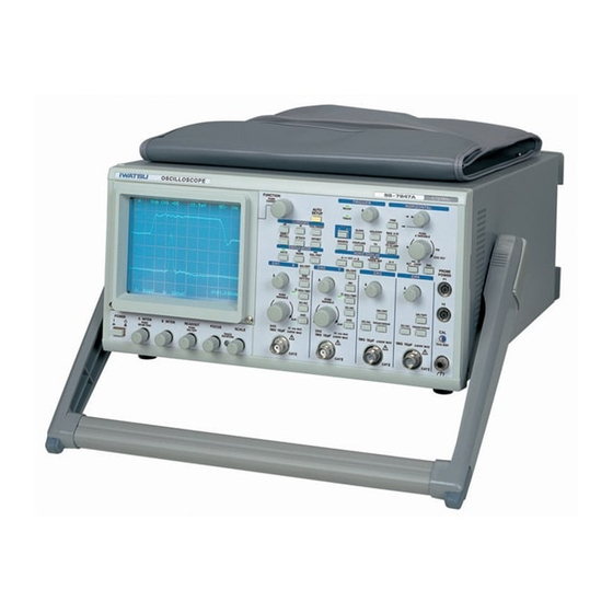
- Page 15 SS-7847A Bandwidth ◇ The SS-7847A oscilloscope has a vertical axis range of 5 mV/div to 50 mV/div and a bandwidth of 470 MHz for both CH1 and CH2. ◇ Since the above range is three times the bandwidth of 156 MHz, it is ideal for observing ITU-T (formerly CCITT), G.703 and other high-speed communications networks.
-
Page 16: Section 1. Operating Points
Section 1. Operating Points 1.1 Front panel Figure 1.1.1 shows the overall view. Refer to page 2 and the pages that follow for details. Figure 1.1.1 Front Panel I (Overall view) Symbols on the panel Warning symbol This symbol calls the user's attention to the descriptions in the instruction manual. This symbol is marked near the CH1 to CH4 INPUT terminals. -
Page 18: Vertical Axis
1.1.2 Vertical axis See Figure 1.1.3. Figure 1.1.3 Front Panel II ① INPUT connectors (CH1 to CH4): Connections for input signals. [Note] Strictly observe the maximum limit on the input voltage as displayed on the panel. ②【 【 【 【 【 9 5V-2mV :】 】 】 】 】 (CH1, CH2) knob: PUSH VARIABLE VOLT/DIV switch: Selects the vertical sensitivity in 1-2-5 seteps (refer to "2.5.1 Vertical Sensitivity "). -
Page 19: Horizontal Axis, Etc
1.1.3 Horizontal Axis, etc. See Figure 1.1.4. Figure 1.1.4 Front Panel III (Horizontal Section, etc.) ①【 【 【 【 【 9 s-ns :】 】 】 】 】 knob: PUSH VARIABLE TIME/DIV switch : Selects the sweep rate in 1-2-5 steps (refer to "2.7.1 Sweep Rate"). -
Page 20: Trigger Section And Display Mode Section
1.1.4 Trigger Section and Display Mode Section See Figure 1.1.5. ① TRIG LEVEL【 【 【 【 【 5 6】 】 】 】 】 knob: Selects the trigger level (refer to "2.9.4 Trigger Level"). ② READY indicator: Lights while waiting for signals. ③... -
Page 21: Functions, Cursors, Sweep Modes, Etc
1.1.5 Functions, Cursors, Sweep Modes, etc. See Figure 1.1.6. ① 【 【 【 【 【 FUNCTION】 】 】 】 】 PUSH COARSE pulse switch: The delay time, cursor position, etc. can be set by turning or pressing this knob. Fine adjustment can be effected by turning this knob. -
Page 23: Section 2. Basic Operation
General Perform basic operation using CAL output and a signal generator so as to become familiar with this instrument. The Iwatsu Test Instruments Corporations SG-4105 is used for the signal generator. ◇ ◇ ◇ ◇ ◇ Grounding Connect the measurement grounding terminal (Right side of CH4 INPUT) to GND of the circuit being measured. - Page 24 ◇ ◇ ◇ ◇ ◇ How to read the screen ・ Main contents of display A TRIGGER A TRIGGER A TRIGGER A TRIGGER Sweep A SWEEP RATE HOLDOFF TIME SOURCE SLOPE COUPLE LEVEL magnification B TRIGGER B TRIGGER B TRIGGER B TRIGGER B SWEEP RATE DELAY TIME...
- Page 26 Table 2.1.1 Measurement conditions of AUTO SETUP Vertical deflection system Triggering Vertical sensitivity VOLTS/DIV : When the frequency is between SOURCE : Detected in the order of CH1 and CH2 50 Hz and 100 MHz, 2 mV to 5 COUPLING: DC V/div with an amplitude of 1.5 to : When the former setting is TV 8 div...
-
Page 27: Probe Compensation
2.2 Probe Compensation Adjust the waveform on the attached probe. Be sure to confirm that the waveform of the probe is compensated correctly before using the probe. Operating method Procedures ① ① ① ① ① Set this unit as follows: CH1 VOLTS/DIV : 10 mV : OFF (GND released) AC/DC... -
Page 29: Vertical And Horizontal Positioning
2.4 Vertical and Horizontal Positioning Adjust the vertical and horizontal positions. This function is used to move the waveform to a position where it can be observed easily or when performing comparative measurement of two or more waveforms by laying one waveform on another. -
Page 30: Vertical Deflection System
2.5 Vertical Deflection System 2.5.1 Vertical Sensitivity Set the amplitude of waveform to a size suitable for viewing. a. CH1 and CH2 Operating method Procedures Setting the TIME/DIV 1 : 10 mV 2 : 10 mV ① ① ① ① ① Select the vertical sensitivity by turning【 【 【 【 【 】... -
Page 31: Input Coupling
2.5.2 Input coupling Select a coupling mode suitable for observation according to the type of input signal. Operating method Procedures Selecting GND ① ① ① ① ① Set GND to ON by pressing GND of CH1 (the GND mark is displayed in the lower left hand corner on the screen). -
Page 32: Input Resistance
2.5.3 Input resistance This is the function to select the input resistance. Operating method Procedures ① ① ① ① ① Select 50 Ω Ω Ω Ω Ω or 1 MΩ Ω Ω Ω Ω by pressing 50 Ω Ω Ω Ω Ω /1 MΩ Ω Ω Ω Ω . ・... -
Page 33: Display Channels
2.5.4 Display channels Signals input to CH1, CH2, CH3 or CH4 are displayed. Operating method Procedures ① ① ① ① ① Select ON (display) or OFF (non-display) of each channel by pressing CH1, CH2, CH3, CH4 ON/OFF . ・ An example where CH1, CH2, CH3, CH4 ON/OFF are set to ON is shown on the left. -
Page 34: Sum And Difference
2.5.6 Sum and difference Add two channels (CH1 + CH2) or subtract one channel from another (CH1 - CH2). Addition or subtraction can be selected by selecting ADD and then setting INV. Operating method Procedures ① ① ① ① ① Set CH1 and CH2 to ON (display) (refer to "2.5.4 Display Chan-nels"). -
Page 36: Offset
2.5.8.2 PROBE P1/P2 offset Thisif the function to set the offset voltage of the FET probe to be connected to the PROBE POWER terminal (P1/P2) of this unit. Operating method Procedures Selecting on SYS-MENU No function display → ① ① ① ① ① Set all function to OFF and set the 【 【 【 【 【 FUNCTION】 】 】 】 】 key to the invalid state *1. -
Page 37: A Sweep And B Sweep
2.6 A Sweep and B Sweep This is the function to select A sweep or B sweep. Operating method Procedures ① ① ① ① ① Select A or B by pressing A B . ・ The indicator lights when B is selected. A : For setting the sweep rate and trigger for normal sweep B : For setting the sweep rate and trigger for delayed sweep Sweep rate... -
Page 38: Sweep Rate And Magnification
2.7 Sweep Rate and Magnification 2.7.1 Sweep Rate Select the sweep rate (TIME/DIV) of A sweep or B sweep. Operating method Procedures Selecting A/B sweep ① ① ① ① ① Select A sweep or B sweep (the indicator lights) by pressing A B . -
Page 39: Ch2 Delay Adjust (Ch2 Dly)
The lag of delay time including the two connection cables or probes can also be adjusted. Connection Connect cables as follows: Signal Generator [Ex.] Iwatsu SG-4105 SS-7847A INPUT OUT PUT Cables or probes... -
Page 40: Sweep Mode
2.8 Sweep Mode Select the sweep mode (AUTO, NORM, or SINGLE). 2.8.1 Repetitive sweep Select AUTO or NORM. Operating method Procedures ① ① ① ① ① Select repetitive sweep by pressing AUTO or NORM in the SWEEP MODE. ・ The AUTO indicator lights when AUTO is selected and NORM indicator, when NORM is selected. ・... -
Page 41: Triggering
2.9 Triggering This is the operation to enable observation of input signals in a stable state on the screen. 2.9.1 Trigger Source Select the trigger source. Operating method Procedures A trigger source ① ① ① ① ① Select A sweep or B sweep (the indicator lights) by pressing 5 ms CH1 A B . -
Page 42: Trigger Slope (Slope)
2.9.3 Trigger Slope (SLOPE) Select the trigger slope. Operating method A trigger slope Procedures 5 ms CH1 + AC ① ① ① ① ① Select A sweep or B sweep (the indicator lights) by pressing 1 ms CH1 + AC A B . -
Page 43: Tv Signal
2.9.5 TV Signal 2.9.5.1 TV signal modes and the number of lines This is the function to set the TV signal mode and the number of lines. Operating method Procedures ① ① ① ① ① Select the TV trigger mode (BOTH, ODD, EVEN, or TV-H) by pressing TV . -
Page 45: Tv Clamp
2.9.6 Event Trigger This is the function to select the event trigger (count or burst). Operating method Procedures ① ① ① ① ① Set the Formats to OFF. ・ Refer to "2.9.5.1 TV signal modes and the number of lines" for the setting method. - Page 46 Count Triggering is set when the specified number of B trigger signals have been counted after the occurrence of A trigger. This function is suitable for confirming the operation of a counter circuit and so on. [Example] An example where the count is set to 6 is shown in the figure below. A trigger B trigger Specified number of counts...
-
Page 47: Horizontal Display
2.10 Horizontal Display Select the horizontal display. Operating method Procedures ① ① ① ① ① Select A, B, ALT, or X-Y by pressing A , B , or X-Y in the HORIZ DISPLAY mode. ・ To select ALT, press A and B simultaneously. ◇... -
Page 48: Trace Separation
2.11 Trace Separation During ALT sweep, move the B-sweep waveform to a position suitable for observation. Operating method Procedures Selecting ALT sweep ① ① ① ① ① Select ALT by pressing A and B in the HORIZ DISPLAY mode. ・ A-sweep waveform and B-sweep waveform are displayed so that one is laid upon the other. -
Page 49: Delayed Sweep
2.12 Delayed Sweep Select the delayed sweep mode (continuous delay, triggered delay). 2.12.1 Continuous Delay B sweep starts after a specified delay time has elapsed from the sweep start point of A sweep. The desired portion of the waveform displayed can be displayed in magnified form. This function is valid when HORIZ DIS- PLAY is set to ALT or B. - Page 50 B sweep ⑥ ⑥ ⑥ ⑥ ⑥ Adjust the delay time by turning 【 【 【 【 【 FUNCTION】 】 】 】 】 . ・ Coarse adjustment in the direction it has so far been turned can be effected each time 【FUNCTION】 is pressed or when it is pressed continuously.
-
Page 51: Triggered Delay
2.12.2 Triggered Delay B sweep starts at the trigger point of B sweep after a specified delay time set from the sweep start point of A sweep. Although the delay pick off jitter can be reduced in this mode, the start point of B sweep is limited to the B trigger point. -
Page 53: Section 3. Cursor Measurement And Counter
Section 3. Cursors Measurement and Counter Measure the time difference and frequency (Δt, 1/Δt) or voltage difference (ΔV) using cursors. ◇ ◇ ◇ ◇ ◇ Selecting of the measurement item ・ Select ΔV (voltage measurement) by pressing ΔV or select Δt (time measurement) by pressing Δt . ◇... - Page 54 Setting cursor 2 ④ ④ ④ ④ ④ Select C2 (cursor 2) by pressing TCK/INDEP . f : H-C2 ・ The function display changes into f : H-C2. Symbol representing a cursor movement ・ Symbol " I " appears above H cursor 2 indicating that cursor 2 is movable.
-
Page 55: Voltage Difference (Δv) Measurement
3.2 Voltage Difference (Δ Δ Δ Δ Δ V) Measurement Measure the voltage between the cursors. Operating method Procedures ① ① ① ① ① Select Δ Δ Δ Δ Δ V by pressing Δ Δ Δ Δ Δ V . ・... -
Page 56: Counter
Setting the tracking ⑥ ⑥ ⑥ ⑥ ⑥ Select TCK (tracking) by pressing TCK/INDEP . f : V-TRACK ・ Function display changes into f:V-TRACK. Symbol representing ・ Symbol "I" appears to the left of V cursor 1 and V cursor 2 a cursor movement V cursor 1 indicating that both cursors are movable. -
Page 57: Section 4. Save/Recall
・ Refer to the following page for the details of the method to input the comment. [SS-7847A ] Save f : SAVE 32 ・ An example where comment "SS-7847A" is input is shown. ・ The comment is saved immediately when it has been input. Executing save [SS-7847A ] Save f : SAVE 32 ⑥... -
Page 60: Section 5. Daily Inspections
Section 5. Daily Inspections a. Methods for servicing ◇Cleaning Wipe off the stains on the casing and cover with soft cloth dampened with a small volume of water or diluted neutral cleanser. If any solvent or cleanser not suitable for cleaning is used, it may cause discoloration or an unexpected fault. - Page 61 ④ ④ ④ ④ ④ Select CALIBRATE by turning 【 【 【 【 【 FUNCTION】 】 】 】 】 . CALIBRATE ・ The message on the left is displayed at the center of the screen. GO:[NORM] EXITP:[SGL/RST] ・ Press SGL/RST to release the system menu. ⑤...
- Page 62 Use an AC power supply within the rating. too low. Replace the battery by contact- Original settings are not ing your nearest Iwatsu sales restored when power is turned on again. agent. (The storage function is not provided in Please buy the oscilloscope in The waveforms cannot be this product.)
-
Page 63: Section 6. Specifications
Section 6. Specifications Type 6 inch, diagonal rectangular flat face, internal graticule, meshless CRT with graticule illumination Display area 8 div x 10 div (1 div=10 mm) Acceleration voltage Approx. 20 kV Vertical deflection system (Y axis) Vertical mode CH1, CH2, CH3, CH4, ADD (CH1+CH2), ALT/CHOP ±... - Page 64 CH3, CH4 Vertical Sensitivity Range 100 mV/div, 500 mV/div Accuracy ± 3 % Bandwidth DC to 400 MHz - 3dB [Note] AC coupled low cutoff frequency (- 3 dB) is 10 Hz ± ± Input RC 1 MΩ 1.5 % // 16 pF 3 pF ±...
- Page 65 Event trigger Count mode Event count range 1 to 65535 Maximum frequency 50 MHz Burst mode Burst signal interval time 0.15 µs to 9.99 s AUTO SETUP Channels Available CH1 and CH2 Frequency 50 Hz to 100 MHz Horizontal deflection system (X axis) Horiz display A, ALT, B, X-Y A sweep...
- Page 66 CAL (Probe calibration signal) Waveform Rectangular wave ± Frequency 1 kHz 0.1 % Duty ratio 49 to 51 % ± Output voltage 0.6 V CH2 OUT ± 30 % (into 50 Ω) Output voltage 20 mV/div Output coupling DC coupling DC to 200 MHz - 3dB (into 50 Ω) Frequency band width ±...
- Page 67 Over Voltage Category Ⅱ Pollution Degree 2...
-
Page 68: Probe Ss-101R
(400MHz combined with SS-7840A, See the page before Section 1 for the Specifications combined with SS-7847A) System Attenuation : 10×±2%... - Page 69 Probe Adjustment LF Adjustment LF compensation is made by connecting the probe to the cal signal and adjusting the compensation trimmer in the BNC-box at end of the probe. Connect the BNC end of the SS-101R to a channel of the oscilloscope. Connect the sprung hook end (1) and the ground lead (2) to the CAL out and GND on the scope Calibrator area.
- Page 71 INDEX CH2 DLY ..........24 A (Sweep) ........... 22, 23 CH2 OUT PUT ........7 A (Trigger) ........... 22 CHOP ..........18 A INTEN ..........13 Clamp ..........29 AC (Input coupling) ......16 Cleaning..........45 AC (Trigger coupling) ......26 Components........
- Page 72 FORMATS .......... 29 Frequency (1/Δt) ........ 38 NORM (Sweep mode) ......25 FUSE ..........7 NTSC ..........28, 29 number of lines ........28, 29 GND (Input coupling) ......16 Grounding ........... 8 ODD (TV trigger mode) ......28 Guide to Diagnosing Faults ....46 Offset ..........
- Page 73 Single sweep ........25 TV-H ........... 28 Slope ..........27 Source ..........26 Specifications ........48 Vertical Deflection System ....15 Stain on the CRT ......... 45 Voltage Difference (ΔV) ...... 40 Storage ..........47 Voltage standing wave ratio (VSWR) ... 17 Subtract (CH1-CH2) ......
- Page 74 Numerals and Symbols HOLDOFF key ....... 5, 37 1MΩ (Input resistance) ....17 INPUT (CH1 to CH4) connectors ..3 50Ω (Input resistance) ....17 INV key ......... 3, 19 1/Δt ..........38 MAG x10 key ......4, 23 Δt ..........38 NORM key ......
- Page 75 Address : 7-41 Kugayama 1-chome Suginami-ku, Tokyo, 168-8511 Japan Phone : +81 3 5370 5483 Facsimile : +81 3 5370 5492 Homepage : http://www.iti.iwatsu.co.jp INDEX-5...