Table of Contents
Advertisement
Quick Links
Advertisement
Table of Contents

Related Manuals for Iwatsu SS-663


Summary of Contents for Iwatsu SS-663
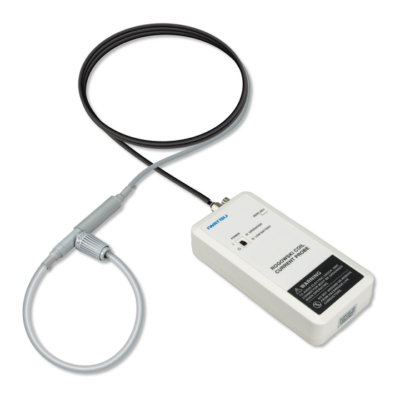
- Page 1 Instruction Manual Rogowski Coil Current Probe SS-663/664/665...
- Page 2 Ⓒ2018 IWATSU ELECTRIC CO., LTD.All rights reserved ....
-
Page 3: Table Of Contents
Contents Preface ········································································ 1 Important Safety Precautions ············································ 1 WARNING ···································································· 2 CAUTION ····································································· 5 Verify packed Items ························································ 7 Components ·································································· 7 Management of instrument ··············································· 8 Repair and sending instrument to be repaired ······················· 8 Cleaning of this instrument ··············································· 8 Chapter 1 Overview ·······················································... - Page 4 Memo...
-
Page 5: Preface
◇ Reproduction or reprinting of the contents of this manual without prior permission from IWATSU is prohibited. ◇ If any question arises about this instrument, contact IWATSU or our sales distributors. Revision History ◇ November 2018: 1st edition... -
Page 6: Warning
(remove the AC adaptor from the outlet when used). Continued use under these circumstances may result in an electric shock or fire. Contact Iwatsu office or our sales distributors for repair. Do not attempt to repair this instrument yourself. - Page 7 Do not modify or disassemble this instrument. Modification or disassembly of this instrument could result in an electric shock, fire, or failure. Repair of a modified product may be refused. Contact Iwatsu office or our sales distributors for repair.
- Page 8 Do not use this instrument when it has failed. Using a failed main unit, cable or AC adaptor may be a cause of an electric shock or fire. In the event of a failure, contact Iwatsu office or our sales distributors for repair.
-
Page 9: Caution
Read the following safety information. (continued) CAUTION Hold the plug when removing the AC adaptor (option) from the outlet. Pulling on the AC adaptor cable will damage the cable. This may be a cause of an electric shock, fire, or failure. ... - Page 10 In addition, wipe off with a dry cloth when water droplets are attached. If not, an electric shock or failure may occur. We recommend that you contact Iwatsu office or our sales distributors for periodic inspection and calibration about once a year.
-
Page 11: Verify Packed Items
Verify packed Items When receiving this instrument, verify the packed items while referring to the following “Components.” If there is a missing item or an item damaged during transportation, immediately contact IWATSU or our sales distributors. Components Rogowski Coil Current Probe ・・・・・1... -
Page 12: Management Of Instrument
Repair and sending instrument to be repaired If a failure occurs, send the instrument to Iwatsu office or our sales distributors. When sending an instrument to be repaired, clearly write the instrument... -
Page 13: Chapter 1 Overview
Chapter 1 Overview Chapter 1 Overview 1.1 Rogowski Coil Current Probe This instrument is a current probe that uses the Rogowski Coil as a sensor. The electric current of the place etc. where the terminal and the electric circuit of the semiconductor device are complicated can be measured by using this instrument. -
Page 14: Features
Chapter 1 Overview 1.2 Features The following describes the features of this instrument. Target of measurement • Semiconductor switch waveforms • Transient current and pulsed current etc. of electrical instrument Compact measurement The Rogowski Coil that detects the electric current thinly has the following advantages for the removable type (In the length of the coil, it is 84mm, and the diameter in the coil section is 1.0mm or less). -
Page 15: Usage Example
Chapter 1 Overview 1.3 Usage Example To measure current using this current probe, place a conductor to be measured through the coil loop, and detect a change in magnetic flux caused by the current flowing through the conductor with the Rogowski Coil as an electromotive force, as shown in the following usage example (conceptual illustration). -
Page 16: Chapter 2 Names And Functions
Chapter 2 Names and Functions of Parts Chapter 2 Names and Functions 2.1 Main Unit ⑥ ⑧ ... -
Page 17: Names And Functions Of Main Unit
► Section 2.1 ⑧ unit. The label describes the following: • TYPE: One of the three models, SS-663/664/665 • Peak Current: One of the current values that the above model handles, 120A, 300A, 600A. • Sensitivity: Voltage sensitivity (mV/A) of the current that the above model handles. -
Page 18: Rogowski Coil Sensor
Chapter 2 Names and Functions of Parts 2.3 Rogowski Coil Sensor ② ④ ① Current direction mark ③ Name Description Rogowski Coil A coil for detecting the current in conductors to be measured. Forms a closed loop during measurement. Covered with an insulating outer sheath for heat resistance and insulation. -
Page 19: Chapter 3 Measurement Principle
Chapter 3 Measurement Principle Chapter 3 Measurement Principle This instrument is designed to measure the current (current waveform) in conductors to be measured. It consists of the Rogowski Coil Sensor part and the main unit (integrator). Sections 3.1 and 3.2 in this chapter describe measurement principles and functions of each part and are concluded with an explanation of a process of measuring the current (current waveform). -
Page 20: Rogowski Coil Sensor
Chapter 3 Measurement Principle 3.1 Rogowski Coil Sensor Figure 3.1 shows that the current I flows through the conductor to be measured. This section describes the principle of detecting this current by the Rogowski Coil step by step. Signal that is Output voltage (V) differential of input (Current waveform) -
Page 21: Main Unit
Chapter 3 Measurement Principle 3.2 Main Unit As illustrated in Figure 3.2, the electromotive force e induced in Section 3.1 is brought in the input part of the main unit through the sensor cable. Observation with an oscilloscope (not included) Main unit (in the dotted area) and other monitoring Sensor cable (coaxial) -
Page 22: Chapter 4 Measurement
Chapter 4 Measurement Chapter 4 Measurement 4.1 Preparation for Measurement (1) Have this instrument, a monitoring device, and a target to be measured ready. * A monitoring device means an oscilloscope, DVM, recorder, and other devices. (2) Place four AA dry batteries in the main unit, or connect the AC adaptor (option) to this instrument. -
Page 23: Measurement Procedure
Chapter 4 Measurement 4.2 Measurement Procedure (1) Make sure that all preparations described in the previous section are completed. (2) Set up a target to be measured so that it can be used. Do not energize the target to be measured even when it is ready to be used. - Page 24 Chapter 4 Measurement The current detection polarity is shown as in the following figure. Positive polarity is output by current flowing in the direction indicated by the current direction mark shown on the joint box. Current to be measured Figure 4.2 Current Detection Polarity (4) Turn on this instrument (this instrument is turned on by turning the slide switch shown in the following figure to the I side and off by moving the switch to the O side).
- Page 25 Chapter 4 Measurement c) Turn the screwdriver while watching the monitoring device to perform ZERO point adjustment. ・ When adjusting the DC offset voltage (zero CAUTION point), included accessory Adjustment Screwdriver, align the tip of the screwdriver with the adjustment slot, and turn it without applying excessive pressure.
-
Page 26: Before Measurement
Chapter 4 Measurement 4.3 Before Measurement This section describes notes on accuracy and the handling of the Rogowski Coil Sensor part when measuring the current using this instrument. 4.3.1 To Achieve Accurate Measurement As explained in Chapter 3 “Measurement Principle,” the Rogowski Coil is a wire rod wound tight around a tube-like wick material, as illustrated in Figure 3.1. - Page 27 Chapter 4 Measurement 4.3.2 To Minimize Influence of Fluctuations in Voltage If there is a part whose voltage fluctuates around the Rogowski Coil Sensor part, electrostatic coupling between the part and the Rogowski Coil will occur. This may influence the output from this instrument. If possible, place the Rogowski Coil Sensor part away from the part whose voltage fluctuates.
- Page 28 We recommend that you replace a deformed coil or a coil with its surface damaged, in order to maintain safety and accurate measurement. Contact Iwatsu office or our sales distributors for replacement.
-
Page 29: Chapter 5 Specifications
Chapter 5 Specifications Chapter 5 Specifications 5.1 Specifications Basic specifications SS-663 SS-664 SS-665 Sensitivity [mV/A] Peak current [kA] Peak di/dt [kA/μs] Absolute maximum di/dt Peak [kA/μs] RMS [kA/μs] to 30MHz [-3dB], f :Low frequency cutoff Frequency bandwidth Low frequency cutoff... - Page 30 Chapter 5 Specifications Environmental characteristics Operating 0 ℃ to 40 ℃, below the moisture temperature and amount of 80 %RH humidity range Storage -10 ℃ to 60 ℃, below the moisture temperature and amount of 80 %RH humidity range Operating altitude ≦2,000m at ≦25 ℃...
-
Page 31: Appearance
Chapter 5 Specifications 5.2 Appearance (1) Main Unit Unit: mm... - Page 32 Chapter 5 Specifications (2) Rogowski Coil Sensor Unit: mm...
- Page 33 Contact Us Overseas Sales Sect. Sales Dept. No.2, : 7-41, Kugayama 1-Chome, Suginami-ku, Tokyo, 168-8501 Address Japan : +81 3 5370 5483 Phone Facsimile : +81 3 5370 5492 : http://www.iti.iwatsu.co.jp : info-tme@iwatsu.co.jp E-mail...
- Page 34 SS-663/664/665...