Advertisement
Quick Links
Installation Instructions
Models HMS-S / HMS-D
Models HMS-SE / HMS-DE (Spanish versions)
Models HMS-SP / HMS-DP (Portuguese versions)
Single/Dual Action Manual Pull Station
INTRODUCTION
PROGRAMMING
INSTRUCTIONS
OPERATION
P/N 315-033200-7
The Model HMS-S and HMS-D Manual Stations, and
their Spanish and Portuguese versions, from Siemens
Industry, Inc., are field installed addressable devices
containing advanced control panel communication
technology. This technology, which provides two-
direction communication with the control panel,
produces an Intelligent Initiating Device. The HMS-S/-
SE/-SP are single action; the HMS-D/-DE/-DP are
double action.
Refer to Figure 1 to locate the opening on the MS cover that allows access to the
programming holes which are on the HMS printed circuit board.
To connect the HMS to the DPU Programmer/Tester,
insert the plug from the DPU cable provided with the
Programmer/Tester into the opening on the HMS as
shown in Figure 2. Because HMS devices are polarity
insensitive, the programming plug can be inserted into
the programming holes in either direction.
To prevent potential damage to the DPU DO NO
connect an HMS to the DPU until at least one wire is
removed from terminals 1 or 2 of the HMS.
Follow the instructions in the DPU Manual
(P/N 315-033260) to program the HMS to the desired
address. Record the device address on the label
located on the HMS front panel. The HMS can now
be installed and wired to the system.
The HMS-S and HMS-D manual stations, as well as their Spanish and Portuguese
versions, operate with the FireFinder-XLS or FS-250 Control Panels via the DLC or FS-
DLC Device Loop Card.
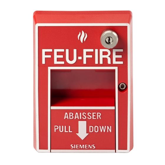
All HMS manual station housings have a pull down lever that locks in position after
releasing a spring loaded switch. (See Figure 4.) To indicate the manual station is
activated, the pull down lever remains down and locked until the station is physically
reset.
The HMS-D/-DE/-DP have an additional lever labeled PUSH IN/EMPUJE/EMPURRE
which must be operated first.
All models are reset by opening the hinged housing cover with an Allen key and then
closing and locking the cover.
firealarmresources.com
Figure 1
MS Cover
PROGRAMMING
POINTS
DO NO
DO NOT T T T T
DO NO
DO NO
LOCATING TAB
Figure 2
Connecting the DPU Plug
Siemens
Siemens Industry
Siemens
Industry
Industry, , , , , Inc.
Industry
Siemens
Siemens
Industry
Building
Building T T T T T ec
Building
ec
ec
hnologies Di
hnologies Di
Building
Building
ec
echnologies Di
hnologies Di
hnologies Division
OPENING TO
PROGRAMMING
POINTS
PLUG FROM
DPU
Inc.
Inc.
Inc.
Inc.
vision
vision
vision
vision
Advertisement

Related Manuals for Siemens HMS-S


Summary of Contents for Siemens HMS-S
- Page 1 HMS front panel. The HMS can now be installed and wired to the system. OPERATION The HMS-S and HMS-D manual stations, as well as their Spanish and Portuguese versions, operate with the FireFinder-XLS or FS-250 Control Panels via the DLC or FS- DLC Device Loop Card.
- Page 2 HOUSING HINGED 3½ in. TO BACKPLATE NAMEPLATE 3 in. SURFACE BACKPLATE LOCKING SCREW MOUNTING ENCLOSURE HOUSING FLUSH MOUNTING ENCLOSURE Figure 4 Mounting The HMS ELECTRICAL RATINGS Siemens Industry, Inc. Building Technologies Division P/N 315-033200-7 Florham Park, NJ Document ID A6V10239110 firealarmresources.com...