
Related Manuals for Honeywell Morley-IAS ZX Series


Summary of Contents for Honeywell Morley-IAS ZX Series
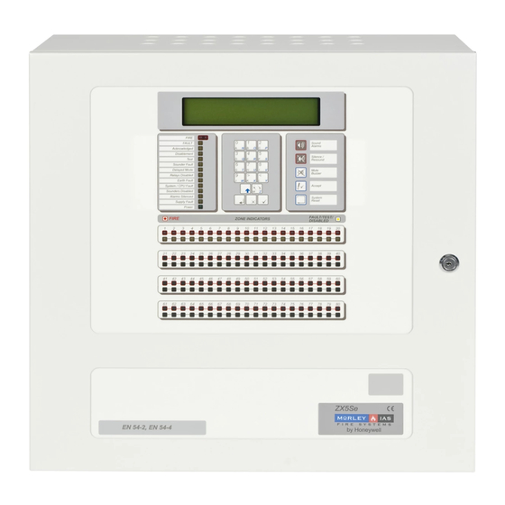
- Page 1 ZX Fire Alarm Control Panels MORLEY-IAS ZX1Se ZX2Se ZX5Se Document No. 996-175-000-1, Revision 01 commissioning manual ZX10Se This manual should not be left with the end user...
-
Page 2: Table Of Contents
ZX Fire Alarm Control Panels MORLEY-IAS Table of Contents INTRODUCTION ....................1 ............................1 OTICE ......................1 ARNINGS AND AUTIONS ........................2 ATIONAL PPROVALS EN54 I ........................2 NFORMATION USER CONTROL LEVELS ...................4 ........................4 EVEL EFINITION ........................4 ASSWORDS ........................4 EVEL ASSWORD CONTROLS AND DISPLAYS ................5 ..........................5 ONTROL KEYS LED I... - Page 3 MORLEY-IAS ZX Fire Alarm Control Panels 5.3.4 Devices..........................28 5.3.4.1 Changing Device Information ..................... 28 5.3.4.2 8-Way Input Units........................29 5.3.5 Remote Control ........................ 29 5.3.5.1 Panel Status Outputs ......................... 29 5.3.5.2 Simulating Control Keys ......................29 ..........................30 OUNDERS 5.4.1 Sounder Output Types .....................
- Page 4 ZX Fire Alarm Control Panels MORLEY-IAS 14 SYSTEM EVENTS OPTION ................52 14.1 E ...........................52 VENT ODES 14.1.1 General Events .........................53 14.1.2 Event Logic ........................53 14.1.3 Define Event Outputs......................54 15 NORMAL OPERATION..................54 16 SUPPLEMENTARY INFORMATION ..............55 16.1 L ......................55 OCATING ARTH AULTS 16.2 O ................56...
-
Page 5: Introduction
• If System Sensor / Morley-IAS / Honeywell Multi-sensor or Laser devices are incorporated into your installation, ensure that you have the current Universal Loop Driver card appropriate to the protocol you are using. If you have any doubt as to the correct version to fit, please contact Technical Support. -
Page 6: National Approvals
MORLEY-IAS ZX Fire Alarm Control Panels CAUTION: A Lithium Battery is used for Data Retention. Replace only with the same or equivalent type. Contact the Service Organisation for Replacement. This symbol identifies that the panel uses a safety isolating mains transformer. 1.3 National Approvals This equipment must be installed and operated in accordance with these instructions and the appropriate national, regional and local regulations specific to the country and location of the... - Page 7 ZX Fire Alarm Control Panels MORLEY-IAS • In addition to the functions required by EN54-2, the panel supports a number of EN54 ancillary functions that are not required by EN54. These are outlined below: Ancillary Function Manual Section Day Mode Options: Sensitivity Mode &...
-
Page 8: User Control Levels
MORLEY-IAS ZX Fire Alarm Control Panels 2 User Control Levels 2.1 Level Definition • The ZX1Se, ZX2Se, ZX5Se and ZX10Se Fire Alarm Control Panels have three user control levels. • At all three levels, the LED Displays indicate the condition of the installation, the Zone LED Displays indicate the location of any fire alarm or fault and the alphanumeric display gives more detailed fire alarm or fault information. -
Page 9: Controls And Displays
ZX Fire Alarm Control Panels MORLEY-IAS 3 Controls and Displays 3.1 Control keys • The control panel has two groups of control keys. • A bank of five keys contains the four system control keys: Sound Alarms, Silence / Resound, Mute, Accept and System Reset. -
Page 10: Front Panel Led Indications
MORLEY-IAS ZX Fire Alarm Control Panels Key Legend Symbol Function 0 to 9 Press to enter numbers 0-9 or letters A-J (N-W with Shift) > Press to scroll through fire alarms or faults manually on the display or letter K (X with Shift) <... -
Page 11: Table 3 - Led Functions
ZX Fire Alarm Control Panels MORLEY-IAS Indicator Colour Function How to Clear FIRE The panel has detected a fire alarm Identify and correct the condition condition, or the ‘Sound Alarms’ key causing the alarm and then perform has been pressed. a panel reset. -
Page 12: Alphanumeric Display Indications
MORLEY-IAS ZX Fire Alarm Control Panels 3.3 Alphanumeric Display Indications • The alphanumeric liquid crystal display gives 160 characters of information on a 4-line display. The display is illuminated to assist viewing under dim ambient light conditions. NOTE: Should the AC Mains fail;... -
Page 13: Memory Lock
ZX Fire Alarm Control Panels MORLEY-IAS 3.4 Memory Lock • To make changes that affect the configuration of the system, such as ISOLATE ELSEWHERE adding detectors, the system F1 : T 2A H 250V memory must first be unlocked. • Open the enclosure door and move the memory lock switch to the open SOUNDER... -
Page 14: Enabling Level 2 Or Level 3 Access
MORLEY-IAS ZX Fire Alarm Control Panels 3.5 Enabling Level 2 or Level 3 Access • To enable Level 2 or Level 3 operation, press the SHIFT key. The display will then show: 03-Mar-2007 11.38 All devices are inside working limits [Panel ACTIVE Control Keys INHIBITED] Do you want to enable the control keys? •... -
Page 15: Overview Of Menu Structure
ZX Fire Alarm Control Panels MORLEY-IAS 3.6 Overview of Menu Structure • The commissioning menu options are presented in three different screens (Pages). When the commissioning menu option is selected, the display will show: PAGE 1 03-Mar-2007 11.38 All devices are inside working limits 1)CONFIGURE YES)More Options 2)Inspect... -
Page 16: Table 4 - Menu Function Overview
MORLEY-IAS ZX Fire Alarm Control Panels To define which, if any, of the following day modes are in operation. Day Modes Delayed Mode Sensitivity Mode Verification Mode To define the effective times of operation, (i.e. start and finish). To define system setup parameters. Setup Options To define and configure the operation of the panel in a networked system. -
Page 17: Commissioning A New Installation
ZX Fire Alarm Control Panels MORLEY-IAS 4 Commissioning a New Installation • This section provides a guide to the steps that are required to commission a new installation. • Precise details on how to perform each step, and on the functionality of each programming option, are given in appropriate sections of this manual. -
Page 18: Step 5 - Configure Day Mode Operation (If Required)
MORLEY-IAS ZX Fire Alarm Control Panels • Finally, select the INSPECT option from page 1 of the Commission Menus. Compare the commissioning data entered against the installation sheets. This facility allows the data to be inspected without risking any inadvertent changes. 4.5 Step 5 –... -
Page 19: Configure Option
ZX Fire Alarm Control Panels MORLEY-IAS 5 Configure Option 5.1 Accessing the Configure Option • Page 1 of the Commission menu is shown below: [ Panel in Commissioning mode ] ---------------------------------------------- 1)CONFIGURE YES)More Options 2)Inspect 3)NORMAL OPERATION • The CONFIGURE option allows the Signalling Loops, peripherals, sounders and relays to be programmed. -
Page 20: Auto Learn
MORLEY-IAS ZX Fire Alarm Control Panels 5.2.1 Auto Learn • This facility saves considerable time and effort when installing a system, or when changing sensor configuration. It allows the system to learn for itself what devices have been installed on a particular loop. •... -
Page 21: Calibrate
ZX Fire Alarm Control Panels MORLEY-IAS • This function is useful to establish what the panel thinks should be physically connected to the loop prior to performing a full Auto Learn. 5.2.2 Calibrate • The panel does not perform any automatic drift compensation on the analogue values returned from the detectors. -
Page 22: Devices
MORLEY-IAS ZX Fire Alarm Control Panels • Each zone can have a description assigned to it to identify the area covered by the zone. This description will appear on the liquid crystal display if any sensor in the zone detects a fault or fire. [ Panel in Commissioning mode ] --------------------------------------------- Zone 001 is named "SOUTH ANNEXE... -
Page 23: Changing Device Information
ZX Fire Alarm Control Panels MORLEY-IAS • The Loop & Battery Calculator must be used to determine the maximum number of LEDs able to be turned on in alarm. Loop Zone Address Location Text Event [ P a n e l i n C o m m i s s i o n i n g m o d e ] - - - - - - - - - - - - - - - - - - - - - - - - - - - - - - - - - - - - - - - - - - - - - L 1 Z 0 0 3 A 0 8 6 "... -
Page 24: Location Text
MORLEY-IAS ZX Fire Alarm Control Panels • Press the appropriate number to select the required option. Press ‘No’ to return to the device information display. NOTE: This change facility is only available while in the configure mode. It cannot be invoked from the INSPECT option, thus preventing inadvertent changes to the system. -
Page 25: Device Events
ZX Fire Alarm Control Panels MORLEY-IAS • For example, suppose the word ‘CORRIDOR’ is to replace the text ‘ROOM 87’ from the above example. Select ‘KeyWords’ mode and use the ‘<’ key to erase ‘ROOM 87’ from the display. The cursor symbol ‘_’... -
Page 26: Restoring Sensitivity Defaults
MORLEY-IAS ZX Fire Alarm Control Panels [ Panel in Commissioning mode ] --------------------------------------------- Fire (normally 55 Press ‘No’ to reject the value shown and then enter the required numeric value. For example, enter a level of 62. The display will then prompt the pre-alarm threshold level. [ Panel in Commissioning mode ] --------------------------------------------- Pre-Alarm = 45... -
Page 27: Device Actions
ZX Fire Alarm Control Panels MORLEY-IAS • To reset the sensitivity thresholds for all devices: Disconnect the devices from the loop and perform an auto-learn. Reconnect the devices to the loop and perform an auto-learn. • NOTE: Apollo I/O Units will reset to the factory default setting of FAULT. 5.2.4.6 Device Actions •... -
Page 28: Class Change
MORLEY-IAS ZX Fire Alarm Control Panels Closing the input produces a ‘warning’ message on the display. The common 1. Fault ‘Fault’ LED and the corresponding zone fault LED will also illuminate. Closing the input puts the designated zone into fire. ‘True’ Break Glass Call Zone Fire Points should ALWAYS be set to this option. -
Page 29: Groups / Group Disablements
ZX Fire Alarm Control Panels MORLEY-IAS 5.2.4.8 Groups / Group Disablements • The group assignment / group disablement function allows a range of detectors and input devices to be disabled remotely from the panel using a single input device. The initiating input device can be any loop-input circuit, call point or peripheral input circuit. -
Page 30: Ancillary Led (Morley-Ias & System Sensor)
MORLEY-IAS ZX Fire Alarm Control Panels • Repeat the last 3 items above for each ancillary sounder fitted. Note that when you have added an ancillary sounder to a device, the Text description displayed in the ‘Devices’ menu will be modified such that a ‘+’(positive) sign will be appended to the description. -
Page 31: Peripherals
ZX Fire Alarm Control Panels MORLEY-IAS 5.3 Peripherals • All panels have the facility to drive various Input and Output devices on the RS485 peripheral bus (the left-hand serial port D on all base cards). Select the configure option from page 1 of the Commission menus. -
Page 32: Calibrate
MORLEY-IAS ZX Fire Alarm Control Panels • Pressing any key then restores the display to the normal commissioning menu. • The Auto Learn sequence can be used as many times as required and does not affect the text description used to describe the location of each sensor. Always verify that the system has found all devices correctly. -
Page 33: 8-Way Input Units
ZX Fire Alarm Control Panels MORLEY-IAS 5.3.4.2 8-Way Input Units • To change the input action on 8-way input boards press ‘6’ to select the ‘Action’ option. The display will then show how the first input has been configured: [ Panel in Commissioning mode ] --------------------------------------------- Input "... -
Page 34: Sounders
MORLEY-IAS ZX Fire Alarm Control Panels 5.4 Sounders 5.4.1 Sounder Output Types • The system supports three different methods of connecting EN54-2 7.11 sounders: EN54 Delays to Outputs. Connected directly to terminals on the base card. Connected to addressable sounder modules on any of the signalling loops. -
Page 35: Pattern On
ZX Fire Alarm Control Panels MORLEY-IAS • This display shows several pieces of information. To avoid ambiguity as to what can be modified, the display will flash the item that can be changed. If this item is a number and you want to change it, then simply type the new value over the top. -
Page 36: Pattern Pulse
MORLEY-IAS ZX Fire Alarm Control Panels EN54-2 7-11c Delays exceeding 600 secs are not compliant. Delays to EN54 Outputs NOTE: ALL delay and pulse timers start and count down from the recognition of the first alarm condition. 5.4.2.4 Pattern PULSE •... -
Page 37: Pattern Off-Pulse-On
ZX Fire Alarm Control Panels MORLEY-IAS Zone 1 Call Point in Alarm Zone 1 Sensor 1 Zone 2 Sensor 1 Zone 1 Sensor 2 in Alarm in Alarm in Alarm No Action No Action Pattern Validated SOUNDERS SOUNDERS SOUNDERS 5.4.2.6 Pattern OFF-PULSE-ON •... -
Page 38: Pattern Pulse-On-On
MORLEY-IAS ZX Fire Alarm Control Panels 5.4.2.8 Pattern PULSE-ON-ON [ Panel in Commissioning mode ] --------------------------------------------- Pattern zone 1/2 Sensors 001 to 080 PULSE/ON -> ON 120s • RESULT: Sounder circuit A will turn on if two or more detectors have gone into fire in zone 1, or two or more in zone 2 etc. -
Page 39: Overriding Delays At Level 1
ZX Fire Alarm Control Panels MORLEY-IAS • When shown on the display, the letter ‘P’ appears in front of the address. This indicates the output is on the peripheral bus. A letter is added after the address to indicate relay A, B, C or D. •... -
Page 40: Relays
MORLEY-IAS ZX Fire Alarm Control Panels 5.5 Relays • Most of the programming and functions of the relay outputs are the same as for the programmable sounders. The exceptions are: There is no circuit monitoring on any relay outputs and as such any open or short circuits occurring on any external wiring cannot be detected and is, therefore, ignored. -
Page 41: Time / Date Option
ZX Fire Alarm Control Panels MORLEY-IAS 7 Time / Date Option • Page 2 of the Commission menu is shown below: [ Panel in Commissioning mode ] --------------------------------------------- 1)Time/Date 2)Program Integrity 3)Power Supplies 4)Passwords • The Time / Date option allows the various time and date functions to be checked or modified. •... -
Page 42: Crystal
MORLEY-IAS ZX Fire Alarm Control Panels 7.3 Crystal • The bus operating frequency is precisely measured during manufacture. The measured value is marked on the CPU board. • This option allows the measured crystal frequency to be entered into the memory so that the software can employ an adjustment factor to maintain an accurate date and time clock. -
Page 43: Program Integrity Option
ZX Fire Alarm Control Panels MORLEY-IAS 8 Program Integrity Option • This option shows the status of the system memory. • To select the Program Integrity option, press ‘2’ from page 2 of the Commissioning Menus. The display then shows the status in the following format: [ Panel in Commissioning mode ] --------------------------------------------- *Program OK . -
Page 44: Power Supplies Option
MORLEY-IAS ZX Fire Alarm Control Panels 9 Power Supplies Option • This option displays the current state of the AC Mains and Battery supplies. • Should a fault occur and the AC Mains fail, the backlighting on the alphanumeric liquid crystal display will be turned off to conserve battery power. - Page 45 ZX Fire Alarm Control Panels MORLEY-IAS Be aware that if the level 2 access timeout has been set to ‘never’, i.e. a value of ‘0’ was entered, accessing this menu will clear it, although the value of ‘1’ is displayed and a one minute timeout will be instigated.
-
Page 46: Day Mode Option
MORLEY-IAS ZX Fire Alarm Control Panels 11 Day Mode Option • Page 3 of the Commission menus is shown below: [ Panel in Commissioning mode ] --------------------------------------------- 1)Day mode 2)Setup options 3)Network [1] 4)Events 5) Talk To Slave This option is displayed if the panel is networked to a slave panel. •... -
Page 47: Delayed Mode
ZX Fire Alarm Control Panels MORLEY-IAS NOTE: Only one mode of operation can be selected to be operational at one time. 11.2 Delayed Mode • EN54-2 7.11 The panel can be configured to operate in a delayed mode during the daytime in any specified zone. EN54 Delays to Outputs •... -
Page 48: Sensitivity Mode
MORLEY-IAS ZX Fire Alarm Control Panels [ Panel in Commissioning mode ] --------------------------------------------- Stage 1 time = 30 seconds OK ? • Press ‘Yes’ to accept and step on. Press ‘No’ to change and then enter the required end time using the number buttons. -
Page 49: Commissioning Sensitivity Mode
ZX Fire Alarm Control Panels MORLEY-IAS • These alternative thresholds are programmed to operate only at certain times of the day and at all other times the thresholds will return to normal. This facility is very flexible. It should only be used in certain specialized applications and with great care. -
Page 50: Commissioning Verification Mode
MORLEY-IAS ZX Fire Alarm Control Panels The alarm verification feature should not be used as a substitute for proper detector location/applications or regular system maintenance. Alarm verification features are intended to reduce the frequency of false alarms caused by transient conditions. They are not intended to compensate for installation design errors or lack of maintenance. -
Page 51: Setup Option
ZX Fire Alarm Control Panels MORLEY-IAS 12 Setup Option • Setup options define the way in which the panel is configured, such as the number and type of loop driver boards fitted. They should be checked when a panel is first installed, but will rarely need altering after this time. -
Page 52: Event Log
MORLEY-IAS ZX Fire Alarm Control Panels During normal operation when everything is working normally, a Site Name message will appear on the bottom line of the alphanumeric display. This can be the installers name, site name etc. If a fault occurs the alphanumeric display will automatically show a Service Phone telephone number to call for help. -
Page 53: Networks Option
ZX Fire Alarm Control Panels MORLEY-IAS 13 Networks Option • Network options define the way in which the panel is configured to operate on a networked system. These options, such as the panel address, should be checked when a system is first installed, but will rarely need changing after this time. -
Page 54: Portb Protocols
MORLEY-IAS ZX Fire Alarm Control Panels Network Option Option setting Comments Panel network-address 1 to 99 Enter Master’s own address, e.g.. 4. number Quantity of slave 1 to 99 Number of slaves DIRECTLY connected to the Master, i.e. processors via port C. Slave CPU 1 is at 1 to 99 The address of the first slave panel. -
Page 55: Table 14 - Port B Protocol Settings
ZX Fire Alarm Control Panels MORLEY-IAS Network Option Protocol Option Comments setting Panel Network / Graphics PC Default setting. Pager A (Fire Zone ‘nnn’) Pager B (Fire Zone ‘nnn’ + 40 character zone and sensor location.) Two-way PC Interface (Gives Faults and Alarms with acknowledgment.) One-way PC Interface (Gives Faults and Alarms.) Table 14 –... -
Page 56: System Events Option
MORLEY-IAS ZX Fire Alarm Control Panels 14 System Events Option • System Events provide a flexible way of performing more complex cause-and-effect programming than that available from the standard zoned ringing. Most systems do not require system events. • Individual detectors can be made to generate system events. Entry via a PC is strongly recommended if many detectors are to generate events. -
Page 57: General Events
ZX Fire Alarm Control Panels MORLEY-IAS 14.1.1 General Events • This option allows special system-event operation on several general functions as shown below. Any item set to event ‘0’ means that this item is not in use. General System Event Name When the event is generated Fault Event Detection of a fault... -
Page 58: Define Event Outputs
MORLEY-IAS ZX Fire Alarm Control Panels 14.1.3 Define Event Outputs • All output devices can have two system events directly assigned to them. • A relay style device will turn on if either of the assigned events occurs. • A sounder style device will turn on if the primary event occurs, (Shown as ‘Event-A’), or will pulse if only the secondary event occurs (‘Shown as Event-B’). -
Page 59: Supplementary Information
ZX Fire Alarm Control Panels MORLEY-IAS 16 Supplementary Information 16.1 Locating Earth Faults • The control panel continually checks the wiring to determine if any external wiring has become short circuit to earth. • An indication of an earth fault is given by amber LED Indicators on the panel front. The earth point is normally maintained at 1V above the battery negative terminal. -
Page 60: Overriding Delays On Individual Outputs
MORLEY-IAS ZX Fire Alarm Control Panels 16.2 Overriding Delays on Individual Outputs • The panel allows delays to be set on individual outputs, as required. • It is recommended that a facility is provided, in the installation, to override any delayed circuits at access Level 1. -
Page 61: Fault Signals From Points
ZX Fire Alarm Control Panels MORLEY-IAS 16.3.4 Fault Signals from points: • The control panel can receive & process fault signals from points, under these conditions the faults are indicated as zone faults. 16.3.5 Disablement of addressable points: • The control panel has the facility to disable / enable signals from addressable points at User Level 2, either individually or by complete zones. -
Page 62: Hochiki Multi-Sensor Support
MORLEY-IAS ZX Fire Alarm Control Panels 16.5 Hochiki Multi-Sensor Support • The Hochiki Multi-Sensor is supported as detailed below from panel software version 824 onwards. Previously, from version 698, the multi-sensor was partially supported – operating as an optical smoke device becoming more sensitive with temperatures above 40 °C. -
Page 63: System Sensor/ M-Ias Multi-Sensor & Laser Detectors
ZX Fire Alarm Control Panels MORLEY-IAS 16.6.2 System Sensor/ M-IAS Multi-sensor & Laser detectors • The System Sensor / Morley-IAS Multi-sensor and laser detectors are supported in panel software version 824 onwards and loop driver software version 9 onwards. • There are 6 modes of operation (alarm levels) available on the multi-sensor and 9 on the laser detector, as in the tables below. - Page 64 MORLEY-IAS ZX Fire Alarm Control Panels NOTES Page 60 Document No. 996-175-000-1, Revision 01 Commissioning Manual...
- Page 65 © MORLEY-IAS. All rights reserved. ® The MORLEY-IAS Logo is a registered trademark. MORLEY-IAS Fire Systems, Charles Avenue, Burgess Hill. West Sussex. RH15 9UF. England Web site: www.morleyias.co.uk...