Table of Contents
Advertisement
Quick Links
Advertisement
Table of Contents

Related Manuals for Gigabyte GA-H81TN


Summary of Contents for Gigabyte GA-H81TN
- Page 1 GA-H81TN GA-B85TN GA-H87TN GA-Q87TN User's Manual 12ME0-H81TN0-00R...
- Page 2 Motherboard GA-H81TN Motherboard GA-H81TN Sept. 23, 2013 Sept. 23, 2013 Motherboard GA-B85TN Motherboard GA-B85TN Sept. 23, 2013 Sept. 23, 2013...
- Page 3 Motherboard GA-H87TN Motherboard GA-H87TN Sept. 23, 2013 Sept. 23, 2013 Motherboard GA-Q87TN Motherboard GA-Q87TN Sept. 23, 2013 Sept. 23, 2013...
- Page 4 No part of this manual may be reproduced, copied, translated, transmitted, or published in any form or by any means without GIGABYTE's prior written permission. In order to assist in the use of this product, GIGABYTE provides the following types of documentations: For detailed product information, carefully read the User's Manual.
-
Page 5: Table Of Contents
Table of Contents Box Contents ........................6 GA-H81TN/GA-B85TN/GA-H87TN Motherboard Layout ..........7 GA-Q87TN Motherboard Layout ..................8 Chapter 1 Hardware Installation ..................9 Installation Precautions ..................9 ..................10 Installing the CPU and CPU Cooler ............... 13 Installing the Memory/Expansion Card ............13 Back Panel Connectors .................. 14 Internal Connectors .................. -
Page 6: Box Contents
Box Contents GA-H81TN, GA-B85TN, GA-H87TN or GA-Q87TN motherboard Motherboard driver disk User's Manual I/O Shield (AIO Thin Mini-ITX x1, Standard Type x 1) Screws kit for expansion cards COM serial cable Cable SATA Power x 1 The box contents above are for reference only and the actual items shall depend on the product package you obtain. -
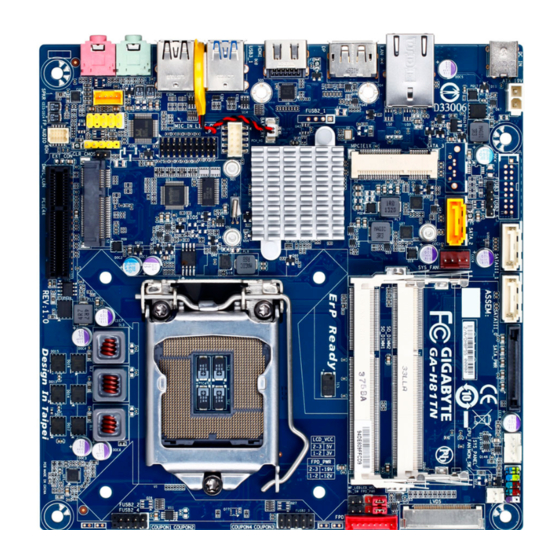
Page 7: Ga-H81Tn/Ga-B85Tn/Ga-H87Tn Motherboard Layout
GA-H81TN/GA-B85TN/GA-H87TN Motherboard Layout PCIE4X SPKR EXT_CON MIC_IN CLR_CMOS LINE_OUT CODEC DMIC_CON USBX_1 BIOS Socket 1150 USB3_1 COM1 BATTERY HDMI Intel H81 / ® B85 H87 SO_DIMM1 SO_DIMM2 GA-H81TN SYS_FAN GA-B85TN GA-H87TN SATA_2 SATA_3 FUSB2_5 SATA_PWR ATX_19V DC_IN SYS_PANEL CPU_FAN SATAIII_0... -
Page 8: Ga-Q87Tn Motherboard Layout
GA-Q87TN Motherboard Layout PCIE4X SPKR EXT_CON MIC_IN CLR_CMOS LINE_OUT CODEC DMIC_CON USBX_1 BIOS Socket 1150 USB3_1 COM1 BATTERY HDMI Intel ® SO_DIMM1 SO_DIMM2 SYS_FAN GA-Q87TN SATAIII_2 SATAIII_3 FUSB2_5 SATA_PWR ATX_19V DC_IN SYS_PANEL CPU_FAN SATAIII_0 SATAIII_1 FUSB3 Intel ® GbE LAN (Note) (Note) The chip is located on the back of the motherboard. -
Page 9: Chapter 1 Hardware Installation
Chapter 1 Hardware Installation Installation Precautions The motherboard contains numerous delicate electronic circuits and components which can become damaged as a result of electrostatic discharge (ESD). Prior to installation, carefully read the user's manual and follow these procedures: Prior to installation, make sure the chassis is suitable for the motherboard. Prior to installation, do not remove or break motherboard S/N (Serial Number) sticker or warranty sticker provided by your dealer. - Page 10 Dual channel memory architecture Support for DDR3 1600/1333 MHz memory modules (Go to GIGABYTE's website for the latest supported memory speeds and memory modules.) Onboard Graphics Chipset: - 1 x HDMI 1.4 port, supporting a maximum resolution of 4096x2160...
- Page 11 4 x USB 3.0/2.0 ports 2 x USB 3.0/2.0 ports 2 x USB 2.0/1.1 ports 1 x RJ-45 port 2 x RJ-45 ports 1 x DC-In power connector Only for GA-H81TN. Only for GA-B85TN. Only for GA-H87TN. Only for GA-Q87TN. - 11 -...
- Page 12 Thin Mini-ITX Form Factor; 17.0cm x 17.0cm prior notice. GIGABYTE recommends 180W power adapters for processors above 84W TDP. Processors with a TDP lower than 84W, may use 150W power adapters. Power adapter connector dimension: 7.4 x 5.1mm, 180W = 19V / 9.47A, 150W = 19V / 7.89A.
-
Page 13: Installing The Cpu And Cpu Cooler
Read the following guidelines before you begin to install the memory expansion card: Make sure that the motherboard supports the memory. It is recommended that memory of the same capacity, brand, speed, and chips be used. (Go to GIGABYTE's website for the latest supported memory speeds and memory modules.) Make sure the motherboard supports the expansion card. -
Page 14: Back Panel Connectors
BIOS Setup, then set Onboard VGA output connect to D-SUB/HDMI under Advanced BIOS Features. Please note the HDMI audio output only supports AC3, DTS and 2-channel-LPCM formats. (AC3 and DTS require the use of an external decoder for decoding.) Only for GA-H81TN. - 14 -... - Page 15 When removing the cable, pull it straight out from the connector. Do not rock it side to side to prevent an electrical short inside the cable connector. Only for GA-H81TN. - 15 -...
-
Page 16: Internal Connectors
Internal Connectors SYS_PANEL SYS_FAN SATAIII_0 DMIC_CON SATAIII_1 ATX_19V SATAIII_2 MON_SW SATAIII_3 SATA_PWR FUSB2_2 SPKR FUSB2_3 BATTERY FUSB2_4 CLR_CMOS FUSB2_5 LCD_VCC FUSB3 FPD_PWR FP_AUDIO WF_LED BL_SW LVDS CPU_FAN COM1 Read the following guidelines before connecting external devices: First make sure your devices are compliant with the connectors you wish to connect. Before installing the devices, be sure to turn off the devices and your computer. - Page 17 The SATA connectors conform to SATA 6Gb/s standard and are compatible with SATA 3Gb/s and SATA 1.5Gb/s standard. Each SATA connector supports a single SATA device. Pin No. SATAIII_0/1 Only for GA-H81TN. Only for GA-B85TN. Only for GA-H87TN. Only for GA-Q87TN.
- Page 18 The SATA connectors conform to SATA 6Gb/s standard and are compatible with SATA 3Gb/s and SATA 1.5Gb/s standard. Each SATA connector supports a single SATA device. Pin No. SATAIII_3 Only for GA-H81TN. Only for GA-B85TN. Only for GA-H87TN. Only for GA-Q87TN.
- Page 19 7) FUSB2_3 (USB Headers) optional USB bracket. For purchasing the optional USB bracket, please contact the local dealer. Pin No. USB- USB- USB+ USB+ No Pin Only for GA-H81TN. Only for GA-B85TN. Only for GA-H87TN. Only for GA-Q87TN. - 19 -...
- Page 20 10) FUSB3 (USB 3.0/2.0 Header) optional 3.5" front panel that provides two USB 3.0/2.0 ports, please contact the local dealer. Pin No. Pin No. VBUS SSRX1- SSRX1+ SSTX2+ SSTX1- SSTX2- SSTX1+ SSRX2+ SSRX2- VBUS No Pin Prior to installing the USB bracket, be sure to turn off your computer and unplug the power cord from the power outlet to prevent damage to the USB bracket.
- Page 21 12) FPD (Flat Panel Display Headers) The FPD is a high-speed interface connecting the output of a video controller in a laptop computer, computer monitor or LCD television set to the display panel. Most laptops, LCD computer monitors and LCD TVs use this interface internally. Pin No.
- Page 22 14/15) CPU_FAN/SYS_FAN (Fan Headers) All fan headers on this motherboard are 4-pin. Most fan headers possess a foolproof insertion design. When connecting a fan cable, be sure to connect it in the correct orientation (the black connector wire is the ground wire). The speed control function requires the use of a fan with fan speed control design. For optimum heat dissipation, it is recommended that a system fan be installed inside the chassis.
- Page 23 17) ATX_19V (2 Pin Power Connector) This power connector is for the integrated 19V chassis power supply. Pin No. +19V 18) MON_SW (Flat panel display switch header) This header allows you to connect an on/off switch for the display. Pin No. Mon_SW - 23 -...
- Page 24 19) SATA_PWR (SATA Power Connector) This connector provides power to installed SATA devices. Connect the included SATA power cable to the SATA_PWR connector. Then connect the SATA/optical drive power connectors to your hard drive and optical drive. 20) SPKR (Speaker Header) This header connects to the speaker on the chassis front panel.
- Page 25 21) BATTERY (Battery Cable Connector) in the CMOS when the computer is turned off. Replace the battery when the battery voltage drops to a low level, or the CMOS values may not be accurate or may be lost. Pin No. RTC Reset Always turn off your computer and unplug the power cord before replacing the battery.
- Page 26 23) LCD_VCC (LVDS Drive Boltage Jumper) 1-2 Close: Set to 3V. 2-3 Close: Set to 5V. (Default setting) 24) FPD_PWR (Flat Panel Display Power Jumper) 1-2 Close: Set to 12V. 2-3 Close: Set to 19V. (Default setting) - 26 -...
- Page 27 25) WF_LED (WIFI Activity Indicator LED Header) This header allows you to connect a WiFi operation indicator LED. Pin No. LED_WLAN 26) BL_SW (Back Light Switch) Pin No. BL_DOWN BL_UP - 27 -...
- Page 28 27) LPT (Parallel Port Header) The LPT header can provide one parallel port via an optional LPT port cable. For purchasing the optional LPT port cable, please contact the local dealer. Pin No. Pin No. STB- BUSY INIT- SLIN- SLCT AFD- ACK- ERR-...
-
Page 29: Chapter 2 Bios Setup
Chapter 2 BIOS Setup BIOS (Basic Input and Output System) records hardware parameters of the system in the CMOS on the saving system parameters and loading operating system, etc. BIOS includes a BIOS Setup program that power is turned off, the battery on the motherboard supplies the necessary power to the CMOS to keep the To access the BIOS Setup program, press the <F2>... - Page 30 Main This setup page includes all the items in standard compatible BIOS Advanced This setup page includes all the items of AMI BIOS special enhanced features. Chipset Boot Security restrict access to the system and BIOS Setup. A supervisor password allows you to make changes in BIOS Setup. A user password only allows you to view the BIOS settings but not to make changes.
-
Page 31: The Main Menu
The Main Menu Once you enter the BIOS Setup program, the Main Menu (as shown below) appears on the screen. Use arrow keys to move among the items and press <Enter> to accept or enter other sub-menu. Main Menu Help The on-screen description of a highlighted setup option is displayed on the bottom line of the Main Menu. - Page 32 BIOS Information Product Name Display the information motherboard model. BIOS Version Display the BIOS version. Build Date and Time Displays the date and time when the BIOS setup utility was created. LAN1/2 MAC Address Displays the MAC address information. Memory Information Size Determines how much total memory is present during the POST.
-
Page 33: Advanced Menu
Advanced Menu Select a submenu item, then press Enter to access the related submenu screen. - 33 -... - Page 34 CPU Type Displays the processor type information. CPU Signature Displays the processor ID information. Microcode Patch Display the information of the processor microcode patch. CPU Speed Display the information of the processor speed. Processor Cores Display the information of the processor core. Intel HT Technology Display Intel Hyper Threading Technology function support information.
- Page 35 L2 Cache Display the information of L2 Cache per Core. L3 Cache Display the information of total L3 Cache per socket. Intel TXT(LT) Support (Note) Enables or disables Intel Trusted Execution Technology (Intel TXT). Intel Trusted Execution ® ® ® Technologyprovides a hardware-based security foundation.
- Page 36 Hard drive information should be labeled on the outside device casing. Enter the appropriate option based on this information. Hot Plug Enables or disable the hot plug capability for each SATA port. (Default: Disabled) Only for GA-H81TN. Only for GA-B85TN. Only for GA-H87TN. Only for GA-Q87TN.
-
Page 37: 2-2-3 Trusted Computing
2-2-3 Trusted Computing Security Device Support Option available: Enabled/Disabled. Default setting is Disabled. - 37 -... -
Page 38: Intel(R) Rapid Start Technology
2-2-4 Intel (R) Rapid Start Technology Intel(R) Rapid Start Technology (Note) Enable/Disable the Intel Rapid Start Technology (IRSTe) funciton. The IRSTe enables your system to get up and running faster from even the deepest sleep, saving time and power consumption. Option available: Enabled/Disabled. -
Page 39: Intel(R) Smart Connect Technology
2-2-5 Intel(R) Smart Connect Technology Enables or disables Intel Smart Connect Technology. (Default: Disabled) - 39 -... - Page 40 This section allows you to enable/disable Intel Active Management Technology (Intel AMT) for remote computer - 40 -...
- Page 41 parallel port. Enables or disables the onboard serial port. (Default: Enabled) Enables or disables the onboard parallel port. (Default: Enabled) - 41 -...
-
Page 42: 2-2-8 H/W Monitor
2-2-8 H/W Monitor Press Enter to view the Hardware Monitor screen which displays a real-time record of the CPU/system CPU/System FAN Fail Detect Enable CPU/System Fan Stop Warning function. Option available: Enabled/Disabled. Default setting is Enabled. CPU/System SMART FAN Control Enable CPU/System Smart Fan function. -
Page 43: Chipset Menu
Chipset Menu Onboard Audio Device Enable/Disable onboard audio controller. Options available: Enabled/Disabled. Default setting is Enabled. DMIC Support Options available: Disabled/Enabled. Default setting is Disabled. Restore AC Power Loss This option provides user to set the mode of operation if an AC / power loss occurs. Power On: System power state when AC cord is re-plugged. - Page 44 XHCI Mode Allows you to determine the operating mode for the xHCI controller in OS. Smart Auto: This mode is available only when the BIOS supports the xHCI controller in the pre-boot environment. This mode is similar to Auto, but it adds the capability to route the ports to xHCI or EHCI according to setting used in previous boots (for non-G3 boot) in the pre-boot environment.
-
Page 45: Boot Menu
Boot Menu The Boot menu allows you to set the drive priority during system boot-up. BIOS setup will display an error Setup Prompt Timeout Number of seconds to wait for setup activation key. Bootup NumLock State Allows you to select power-on state for NumLock function. Options available: On/Off. - Page 46 CSM parameters Launch CSM Enables or disables UEFI CSM (Compatibility Support Module) to support a legacy PC boot process. Enabled Enables UEFI CSM. (Default) Disabled Disables UEFI CSM and supports UEFI BIOS boot process only. Allows you to select which type of operating system to boot. UEFI and Legacy Allows booting from operating systems that support legacy option ROM or UEFI option ROM.
- Page 47 Other PCI device ROM priority Allows you to select whether to enable the UEFI or Legacy option ROM for the PCI device controller other than the LAN, storage device, and graphics controllers. UEFI OpROM Enables UEFI option ROM only. (Default) Legacy OpROM Enables legacy option ROM only.
-
Page 48: Security Menu
Security Menu The Security menu allows you to safeguard and protect the system from unauthorized use by setting up access passwords. There are two types of passwords that you can set: Adminstrator Password Entering this password will allow the user to access and change all settings in the Setup Utility. User Password Administrator Password Administrator password. -
Page 49: Save & Exit Menu
Save & Exit Menu The Exit menu displays the various options to quit from the BIOS setup. Highlight any of the exit options then press Enter. Save Changes and Reset Active this option to reset system after saving the changes. Options available: Yes/No. - Page 50 - 50 -...
- Page 51 - 51 -...
- Page 52 - 52 -...