Table of Contents
Advertisement
Quick Links
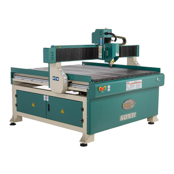
MODEL G0931L
47" X 47" CNC ROUTER
w/T-SLOT TABLE
MANUAL INSERT
For Machines Mfd. Since 02/21
and Owner's Manual Printed 11/21
The Model G0931L is the same machine as the Model G0931 except for maximum Z-axis travel and parts
shown in the parts breakdowns and lists. Except for the differences noted in this insert, all other content in
the Model G0931 Owner's Manual applies to this machine.
: To reduce the risk of serious injury, you MUST read and understand this insert—and
the entire Model G0931 manual—BEFORE assembling, installing, or operating this machine!
If you have any further questions about this manual insert or the differences between the Model G0931L
and Model G0931, contact our Technical Support at (570) 546-9663 or email techsupport@grizzly.com.
COPYRIGHT © APRIL, 2022 BY GRIZZLY INDUSTRIAL, INC.
WARNING: NO PORTION OF THIS MANUAL MAY BE REPRODUCED IN ANY SHAPE
OR FORM WITHOUT THE WRITTEN APPROVAL OF GRIZZLY INDUSTRIAL, INC.
#KS22294 PRINTED IN CHINA
***Keep for Future Reference***
Advertisement
Table of Contents

Related Manuals for Grizzly G0931L


Summary of Contents for Grizzly G0931L
- Page 1 Owner's Manual Printed 11/21 The Model G0931L is the same machine as the Model G0931 except for maximum Z-axis travel and parts shown in the parts breakdowns and lists. Except for the differences noted in this insert, all other content in the Model G0931 Owner's Manual applies to this machine.
- Page 2 Frame Size ................................ NEMA 34 Amps .................................... 4A Speed ................................. 0 - 2000 RPM Type ........................Stepper (Brushless, Permanent Magnet) Power Transfer ................................ Direct Step Resolution ............................ 1.8 deg. Per Step Model G0931L (Mfd. Since 02/21) Model G0931 Page 1 of 2...
- Page 3 RichAuto DSP A11 Handheld Controller with USB Port and Keypad Water Cooled Spindle with Included Water Pump Aluminum Table with T-Track and PVC Padding Tool Touch-Off Pad for Quickly Setting Z-Axis Height Model G0931L (Mfd. Since 02/21) Page 2 of 2 Model G0931...
- Page 4 Main BUY PARTS ONLINE AT GRIZZLY.COM! Model G0931L (Mfd. Since 02/21) Scan QR code to visit our Parts Store.
- Page 5 BUTTON HD CAP SCR M5-.8 X 8 P0931L031 SIDE GUARD COVER P0931L063 HEX NUT M5-.8 P0931L032 CABLE CARRIER P0931L064 Y-AXIS MOVEMENT LABEL BUY PARTS ONLINE AT GRIZZLY.COM! Model G0931L (Mfd. Since 02/21) Scan QR code to visit our Parts Store.
- Page 6 Gantry & Spindle 157-3 157-4 157-1 157-5 157-2 BUY PARTS ONLINE AT GRIZZLY.COM! Model G0931L (Mfd. Since 02/21) Scan QR code to visit our Parts Store.
- Page 7 SPINDLE DIRECTION LABEL P0931L146 STRAIN RELIEF TYPE-3 PG31 P0931L183 X-AXIS MOVEMENT LABEL P0931L147 WRENCH 18 X 21MM OPEN-ENDS P0931L184 Z-AXIS MOVEMENT LABEL BUY PARTS ONLINE AT GRIZZLY.COM! Model G0931L (Mfd. Since 02/21) Scan QR code to visit our Parts Store.
- Page 8 DSP CONTROLLER RICHAUTO A11E P0931L219 WIRE LOOM 50 X 220MM P0931L210 TERMINAL BAR 8P M4-.7 X 12 P0931L220 WIRE LOOM 50 X 160MM BUY PARTS ONLINE AT GRIZZLY.COM! Model G0931L (Mfd. Since 02/21) Scan QR code to visit our Parts Store.
- Page 9 Safety labels help reduce the risk of serious injury caused by machine hazards. If any label comes off or becomes unreadable, the owner of this machine MUST replace it in the original location before resuming operations. For replacements, contact (800) 523-4777 or www.grizzly.com. BUY PARTS ONLINE AT GRIZZLY.COM! Model G0931L (Mfd.
- Page 11 WARRANTY & RETURNS Grizzly Industrial, Inc. warrants every product it sells for a period of 1 year to the original purchaser from the date of purchase. This warranty does not apply to defects due directly or indirectly to misuse, abuse, negligence, accidents, repairs or alterations or lack of maintenance.
- Page 13 (For models manufactured since 02/21) COPYRIGHT © NOVEMBER, 2021 BY GRIZZLY INDUSTRIAL, INC. WARNING: NO PORTION OF THIS MANUAL MAY BE REPRODUCED IN ANY SHAPE OR FORM WITHOUT THE WRITTEN APPROVAL OF GRIZZLY INDUSTRIAL, INC. #KS22105 PRINTED IN CHINA V1.11.21...
- Page 14 This manual provides critical safety instructions on the proper setup, operation, maintenance, and service of this machine/tool. Save this document, refer to it often, and use it to instruct other operators. Failure to read, understand and follow the instructions in this manual may result in fire or serious personal injury—including amputation, electrocution, or death.
-
Page 15: Table Of Contents
Table of Contents INTRODUCTION ..........2 SECTION 4: OPERATIONS ......25 Contact Info............ 2 Operation Overview ........25 Manual Accuracy ........... 2 Workpiece Inspection........26 Identification ........... 3 Choosing Cutter ........... 26 Controls & Components ......... 4 Changing Cutter ........... 27 Controller Functions ........ -
Page 16: Introduction
ID label. This will help us help you faster. tions, specifications, drawings, and photographs in this manual. Sometimes we make mistakes, but Grizzly Technical Support our policy of continuous improvement also means that sometimes the machine you receive is 1815 W. -
Page 17: Identification
Identification Become familiar with the names and locations of the controls and features shown below to better under- stand the instructions in this manual. Z-Axis Stepper Motor (Behind Cover) Z-Axis Tool Setter Spindle X-Axis Limit Motor Switch Y-Axis Stepper Motor (Behind Cover) Z-Axis Limit Switch Cable (Behind Cover) -
Page 18: Controls & Components
Controls & Power Controls Components To reduce your risk of serious injury, read this entire manual BEFORE using machine. Figure 2. Power buttons. E. EMERGENCY STOP Button: Disables Refer to the following figures and descriptions to power to machine. To reset, twist button become familiar with the basic controls and com- clockwise until it pops out. -
Page 19: Controller Functions
Z+ or 3: Moves spindle motor along Z-axis in positive direction. Increases spindle speed during process. Input for "3". XY->0 or 4: Sets work origin of X- and Y-axes (see Page 30). Input for "4". X- or 5: Moves spindle motor along X-axis in neg- ative direction. -
Page 20: Glossary Of Terms
The following is a list of common definitions, terms and phrases used throughout this manual as they relate to this CNC router and woodworking in general. Become familiar with these terms for assembling, adjusting or operating this machine. Your safety is VERY important to us at Grizzly! Compression Bit: A cutting tool with a combi- Axis: Direction of movement. - Page 21 Hold-Down: A clamp used to firmly hold a Spindle Speed: Rotational speed of cutting tool workpiece or fixture to the table. (RPM). Home Position: A fixed point on the machine set Spoilboard: Sacrificial material placed under the with proximity switches. It is the machine zero workpiece that allows the cutting tool to go point on all axes.
-
Page 22: Machine Data Sheet
Customer Service #: (570) 546-9663 · To Order Call: (800) 523-4777 · Fax #: (800) 438-5901 MODEL G0931 47" X 47" CNC ROUTER WITH T-SLOT TABLE Product Dimensions: Weight ................................... 838 lbs. Width (side-to-side) x Depth (front-to-back) x Height ................70 x 62-1/2 x 53-1/2 in. Footprint (Length/Width) ............................58 x 60 in. - Page 23 Y-Axis Motor Frame Size ................................ NEMA 34 Amps .................................... 4A Speed ................................. 0 - 2000 RPM Type ........................Stepper (Brushless, Permanent Magnet) Power Transfer ................................ Direct Step Resolution ............................ 1.8 deg. Per Step Z-Axis Motor Frame Size ................................ NEMA 34 Amps ....................................
-
Page 24: Section 1: Safety
SECTION 1: SAFETY For Your Own Safety, Read Instruction Manual Before Operating This Machine The purpose of safety symbols is to attract your attention to possible hazardous conditions. This manual uses a series of symbols and signal words intended to convey the level of impor- tance of the safety messages. - Page 25 WEARING PROPER APPAREL. Do not wear FORCING MACHINERY. Do not force machine. clothing, apparel or jewelry that can become It will do the job safer and better at the rate for entangled in moving parts. Always tie back or which it was designed. cover long hair.
-
Page 26: Additional Safety For Cnc Routers
Additional Safety for CNC Routers You can be seriously injured or killed by getting clothing, jewelry, or long hair entangled with rotating cutter/spindle. You can be severely cut or have fingers amputated from contact with rotating cutters. You can be blinded or struck by broken cutting tools, wood chips, workpieces, or adjustment tools thrown from the rotating spindle with great force. -
Page 27: Section 2: Power Supply
SECTION 2: POWER SUPPLY Availability Circuit Information Before installing the machine, consider the avail- A power supply circuit includes all electrical ability and proximity of the required power supply equipment between the breaker box or fuse panel circuit. If an existing circuit does not meet the in the building and the machine. - Page 28 Grounding Requirements This machine MUST be grounded. In the event of certain malfunctions or breakdowns, grounding Serious injury could occur if you connect reduces the risk of electric shock by providing a machine to power before completing setup process. DO NOT connect to power until path of least resistance for electric current.
-
Page 29: Section 3: Setup
IMPORTANT: Save all packaging materials until you are completely satisfied with the machine and have resolved any issues between Grizzly or the shipping agent. You MUST have the original pack- aging to file a freight claim. It is also extremely helpful if you need to return your machine later. -
Page 30: Inventory
Inventory The following is a list of items shipped with your machine. Before beginning setup, lay these items out and inventory them. If any non-proprietary parts are missing (e.g. a nut or a washer), we will gladly replace them; or for the sake of expediency, replacements can be obtained at your local hardware store. -
Page 31: Site Considerations
Site Considerations Weight Load Physical Environment Refer to the Machine Data Sheet for the weight The physical environment where the machine is of your machine. Make sure that the surface upon operated is important for safe operation and lon- which the machine is placed will bear the weight gevity of machine components. -
Page 32: Lifting & Placing
Lifting & Placing Leveling For accurate cutting results and to prevent HEAVY LIFT! warping, the table and frame MUST be Straining or crushing injury leveled from side to side and from front to may occur from improperly back on both ends. Re-check the table and lifting machine or some of frame 24 hours after installation, two weeks its parts. -
Page 33: Connecting Cooling Pump
Connecting Cooling Connect either coolant tube from back of machine to cooling pump outlet (see Pump Figure 12). The Model G0931 includes an external pump that Outlet cools the spindle motor. Coolant tubes come pre- installed on the motor and run through the cable carrier. -
Page 34: Connecting Controller
Connecting Connect 50-pin cable to interface board in electrical cabinet, then route cable through Controller hole in cabinet floor (see Figure 14). 50-Pin Cable The Model G0931 includes a RichAuto A11 hand- Connector held motion controller that controls all machine functions using G-code. -
Page 35: Dust Collection
Dust Collection To connect dust collection system to machine: Attach dust shoe bracket end to spindle motor and secure with (1) M5-.8 x 45 cap screw and (1) M5-.8 hex nut (see Figure 16). This machine creates a lot of wood chips/ Spindle Motor dust during operation. -
Page 36: Test Run
Test Run Twist EMERGENCY STOP button clockwise until it springs out (see Figure 18). This resets the switch so the machine can start. Once assembly is complete, test run the machine to ensure it is properly connected to power and safety components are functioning correctly. -
Page 37: Verifying Parameters
Verifying Parameters Pulse Equivalent: X Equival ..........200.000 Y Equival ..........200.000 Z Equival ..........400.000 Machine parameters are essential to any operation. If the parameters are wrong, the machine will not Table Size: produce accurate results, and damage to the X Size ........... - Page 38 Verifying Voltage Parameters Verifying Input Parameters The Voltage Setup screen enables opening or The input configuration screen shows electrical closing of input and output signals to machine inputs sent by various machine components dur- ing operation (see Figure 20). components. The upper row of arrows represents the input side, and the lower row represents the output side (see Figure 19).
-
Page 39: Section 4: Operations
Read books/magazines or get formal training before beginning any proj- ects. Regardless of the content in this sec- tion, Grizzly Industrial will not be held liable for accidents caused by lack of training. -25- Model G0931 (Mfd. Since 02/21) -
Page 40: Workpiece Inspection
Workpiece Choosing Cutter Inspection There are many cutters available. Be sure to choose the right one for your application and Some workpieces are not safe to cut or may material. Read all manufacturer instructions require modification before they are safe to cut. before installing and using a cutter. -
Page 41: Changing Cutter
Changing Cutter Depth and Width of Cut: The cutter must be long enough to reach the maximum plunge depth of the operation and small enough to cut the details of the piece. However, shorter, wider bits will deflect less, leading to more accurate cuts, and they are less prone to wear and breakage. -
Page 42: Clamping Workpiece
Clamping Workpiece Position clamps so workpiece is stable and does not rock. Take into consideration axis positions when G-code runs. Always secure the workpiece to the table with Tighten wing nuts until workpiece is secure clamps to avoid injury and damage to the machine and flat against table on all four sides/ corners. -
Page 43: Adjusting Axis Positions Manually
Secure workpiece to spoilboard. — Depth defines the total depth of material removed. Z Step defines how much mate- Note: Depending on the needs of the rial is removed per pass. For example, workpiece and G-code, it could be appro- a Depth of 1 and Z Step of 0.25 would priate to use additional hold-down clamps, remove 1mm of material over four passes. -
Page 44: Homing Axes
Setting Origin Changing Axis Movement Speed Press HIGH/LOW to toggle between fast and slow speeds. Work origin is the workpiece-specific zero point, Changing Axis Movement Mode the starting point for the toolpath. All three axes need to be zeroed at the work origin before run- Press MODE to toggle between Continuous, ning code. -
Page 45: Creating G-Code File
Creating G-Code File Setting Z-Axis Origin With Tool Setter Verify tool setter parameters are correct according to Verifying Default Parameters on Page 23. Before operations can be run on the Model G0931, a toolpath must be designed and con- Clamp workpiece to table, insert cutter, and verted to G-code. -
Page 46: Uploading & Running G-Code
Uploading & Press OK again to begin operation. Running G-Code — Press RUN/PAUSE to pause axis move- ment. Spindle will continue to spin. Axes can be manually moved while paused. Press RUN/PAUSE again to resume, then IMPORTANT: DO NOT use a USB drive larger OK to resume from new axis position, or than 16GB. -
Page 47: Changing Advanced Settings
Changing Advanced Running G-Code From Controller Internal Memory Settings Press RUN/PAUSE. Scroll to "Internal File" and press OK, then scroll to G-code file and press OK. Screen will display "SetWorkParam" and the Changing advanced settings will change the following parameters: default functions of your machine and how it processes files. -
Page 48: Using Advanced Controls
Using Advanced Manually Setting Controls Spindle Speed All the basic controls of the G0931 are performed Pressing ON/OFF and Z+ or Z- buttons together through single-button commands on the control- while the spindle is running will increase or ler, but some advanced features require multi- decrease the spindle speed through a range of button commands to access. -
Page 49: Section 5: Accessories
DC1816— ⁄ " Solid Carbide Downcut Spiral To reduce this risk, only install accessories recommended for this machine by Grizzly. NOTICE Refer to our website or latest catalog for additional recommended accessories. V-Carve CNC Router Software T28100—V-Carve Desktop Software... - Page 50 Moly-D to maximize compo- nent life and minimize wear. Figure 31. Half-mask respirator with disposable cartridge filters. Figure 33. T27914 Moly-D Machine and Way Oil. www.grizzly.com 1-800-523-4777 order online at or call -36- Model G0931 (Mfd. Since 02/21)
-
Page 51: Section 6: Maintenance
SECTION 6: MAINTENANCE Cleaning & Protecting To reduce risk of shock or accidental startup, always disconnect machine from power before adjustments, Cleaning the Model G0931 is relatively easy. Use maintenance, or service. a brush and shop vacuum to remove debris from the table, rails, and machine surfaces. - Page 52 (see Figure 34). Figure 35. Y-axis guide rail locations. Use a clean shop rag to wipe entire length of guide rails with Grizzly T27914 or ISO 68 equivalent. Turn machine ON and move gantry several times over full range of Y-axis travel to spread lubricant and ensure smooth movement.
- Page 53 Figure 37. X-axis ball screw and guide rails location. Use clean brush to wipe entire length of ball screw threads with Grizzly T27914 or ISO 68 equivalent. Use clean shop rag to wipe entire length of guide rails with Grizzly T27914 or ISO 68 equivalent.
-
Page 54: Coolant
Z-Axis Ball Screw & Guide Rails Use clean brush to wipe entire length of ball screw threads with Grizzly T27914 or ISO 68 Lube Type ....T27914 or ISO 68 Equivalent equivalent. Lube Amount ........As Needed Lubrication Frequency ......Weekly... -
Page 55: Section 7: Service
SECTION 7: SERVICE Review the troubleshooting procedures in this section if a problem develops with your machine. If you need replacement parts or additional help with a procedure, call our Technical Support. Note: Please gather the serial number and manufacture date of your machine before calling. Troubleshooting Motor &... - Page 56 Motor & Electrical (Cont.) Symptom Possible Cause Possible Solution Machine has 7. Spindle bearings at fault. 7. Test by rotating spindle; rotational grinding/loose vibration or noisy shaft requires bearing replacement. operation. 8. One or more stepper driver(s) have 8. Adjust stepper driver DIP switch configuration incorrect DIP switch configuration.
- Page 57 Machine Operations (Cont.) Symptom Possible Cause Possible Solution Finished workpiece 1. Pulse equivalent incorrect. 1. Verify controller parameters and update pulse incorrect size. equivalent (Page 23). 2. Incorrect cutter. 2. Use correct cutter for job. 3. CAD/CAM dimensional or tooling errors. 3.
-
Page 58: Testing Limit Switches
Testing Limit Touch each limit switch target with a scrap piece of iron or steel (see Figure 41). Switches Touch Here If the Model G0931 is no longer homing properly, or one or more axes is unresponsive, test each limit switch for proper operation. Item Needed Scrap Iron or Steel .......... -
Page 59: Updating Richauto Controller Software
Updating RichAuto Use a multimeter to check continuity between limit switches and interface board terminals Controller Software (see Figure 42). — If continuity is confirmed between limit switches and interface board, proceed to If the RichAuto controller displays a blank screen, Step 7. -
Page 60: Setting Stepper Driver Dip Switches
Setting Stepper Compare each stepper driver DIP switch con- figuration to diagram in Figure 45. Driver DIP Switches — If DIP switch does match diagram, DIP switch is set correctly. The DIP (Dual In-line Package) switches on the — If DIP switch does not match diagram, flip stepper drivers control the step size, current, and individual rocker switches until DIP switch speed of the stepper motors. -
Page 63: Warranty & Returns
WARRANTY & RETURNS Grizzly Industrial, Inc. warrants every product it sells for a period of 1 year to the original purchaser from the date of purchase. This warranty does not apply to defects due directly or indirectly to misuse, abuse, negligence, accidents, repairs or alterations or lack of maintenance.