Table of Contents
Advertisement
Quick Links
For questions or help with this product contact Tech Support at (570) 546-9663 or techsupport@grizzly.com
The following change was recently made since the owner's manual was printed:
•
Delta VFD-E replaced by Delta MS300.
Aside from this information, all other content in the owner's manual applies and MUST be read and under-
stood for your own safety. IMPORTANT: Keep this update with the owner's manual for future reference.
For questions or help, contact our Tech Support at (570) 546-9663 or techsupport@grizzly.com.
Revised Parts Breakdown
Variable Frequency Drive
DELTA MS300
S1
+24V
ACM
+10
MI2
MI4
MI1
MI3
R/L1
S/L2
DC
GND
REF
PART #
DESCRIPTION
515V2 P0757Z515V2 VFD DELTA MS300 V2.07.19
WARNING: NO PORTION OF THIS MANUAL MAY BE REPRODUCED IN ANY SHAPE
OR FORM WITHOUT THE WRITTEN APPROVAL OF GRIZZLY INDUSTRIAL, INC.
READ THIS FIRST
523
DCM
SG-
MCM
S2
SG+
SGND
ACI
M01
AVI
AFM
M02
MI6
+24V
DCM
DFM
MI5
MI7
+24V
DCM
515V2
T/L3
U/T1
V/T2
W/T3
DC
+/+1
+2/B1
B2
GND
COPYRIGHT © JULY, 2019 BY GRIZZLY INDUSTRIAL, INC.
#AI20557 PRINTED IN CHINA
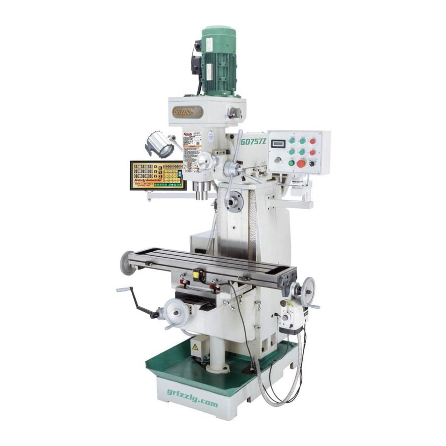
Model G0757Z
***IMPORTANT UPDATE***
For Machines Mfd. Since 07/19
and Owner's Manual Printed 07/15
Old Delta Variable Frequency Drive
New Delta Variable Frequency Drive
Advertisement
Table of Contents

Related Manuals for Grizzly G0757Z


Summary of Contents for Grizzly G0757Z
- Page 1 ***IMPORTANT UPDATE*** For Machines Mfd. Since 07/19 and Owner's Manual Printed 07/15 For questions or help with this product contact Tech Support at (570) 546-9663 or techsupport@grizzly.com The following change was recently made since the owner's manual was printed: •...
- Page 2 To X-Axis Horizontal Spindle Motor Page 63 Connection Control Panel Page 63 Page 68 Page 63 Power Feed Page 67 Spindle Motor Page 63 Page 66 Page 63 Page 67 READ ELECTRICAL SAFETY Model G0757Z (Mfd. Since 07/19) IN OWNER'S MANUAL...
- Page 3 OWNER'S MANUAL (For models manufactured since 02/15) COPYRIGHT © JULY, 2015 BY GRIZZLY INDUSTRIAL WARNING: NO PORTION OF THIS MANUAL MAY BE REPRODUCED IN ANY SHAPE OR FORM WITHOUT THE WRITTEN APPROVAL OF GRIZZLY INDUSTRIAL, INC. #BB17431 PRINTED IN CHINA V1.07.15...
- Page 4 This manual provides critical safety instructions on the proper setup, operation, maintenance, and service of this machine/tool. Save this document, refer to it often, and use it to instruct other operators. Failure to read, understand and follow the instructions in this manual may result in fire or serious personal injury—including amputation, electrocution, or death.
-
Page 5: Table Of Contents
Table of Contents INTRODUCTION ..........2 SECTION 5: ACCESSORIES ......39 Contact Info............ 2 SECTION 6: MAINTENANCE ......44 Manual Accuracy ........... 2 Schedule ............44 Left Front View Identification ......3 Cleaning & Protecting ........44 Right Front View Identification ....... 4 Lubrication ........... -
Page 6: Introduction
ID label (see below). This information is required for us to provide proper tech support, and it helps us determine if updated documenta- tion is available for your machine. Manufacture Date Serial Number Model G0757Z (Mfd. Since 02/15) -
Page 7: Left Front View Identification
Left Front View Identification Spindle Motor Master Control Panel Halogen Work Light Horizontal Arbor Support Vertical Spindle Coolant Nozzle X-Axis Handwheel Splash Electrical Cabinet Base Coolant Pump Model G0757Z (Mfd. Since 02/15) -
Page 8: Right Front View Identification
Right Front View Identification High/Low Gear Selector Coarse Downfeed Lever Fine Downfeed Handwheel Controls Horizontal Spindle X-Axis Handwheel Z-Axis Crank X-Axis Power Feed Y-Axis Handwheel Model G0757Z (Mfd. Since 02/15) -
Page 9: Controls & Components
REVERSE Button (Horizontal Spindle Starts horizontal spindle reverse rotation (clock- wise as viewed from front of machine). G. STOP Button (Horizontal Spindle ): Stops horizontal spindle rotation. H. Variable-Speed Dial: Controls speed of ver- tical spindle. Model G0757Z (Mfd. Since 02/15) - Page 10 C. Graduated Dial: Displays X-axis table move- ment in 0.001" increments, with each revolu- tion equaling 0.200" of travel. Figure 4. Headstock controls. D. Handwheel: Manually positions table. High/Low Gear Selector: Selects between high and low gears on the vertical spindle. Model G0757Z (Mfd. Since 02/15)
-
Page 11: Machine Data Sheet
The information contained herein is deemed accurate as of 7/20/2015 and represents our most recent product specifications. Model G0757Z PAGE 1 OF 3 Due to our ongoing improvement efforts, this information may not accurately describe items previously purchased. Model G0757Z (Mfd. Since 02/15) - Page 12 The information contained herein is deemed accurate as of 7/20/2015 and represents our most recent product specifications. Model G0757Z PAGE 2 OF 3 Due to our ongoing improvement efforts, this information may not accurately describe items previously purchased. Model G0757Z (Mfd. Since 02/15)
- Page 13 The information contained herein is deemed accurate as of 7/20/2015 and represents our most recent product specifications. Model G0757Z PAGE 3 OF 3 Due to our ongoing improvement efforts, this information may not accurately describe items previously purchased. Model G0757Z (Mfd. Since 02/15)
-
Page 14: Section 1: Safety
Everyday ery. Never operate under the influence of drugs or eyeglasses are NOT approved safety glasses. alcohol, when tired, or when distracted. -10- Model G0757Z (Mfd. Since 02/15) - Page 15 EXPERIENCING DIFFICULTIES. If at any time debris. Make sure they are properly installed, you experience difficulties performing the intend- undamaged, and working correctly BEFORE ed operation, stop using the machine! Contact our operating machine. Technical Support at (570) 546-9663. -11- Model G0757Z (Mfd. Since 02/15)
-
Page 16: Additional Safety For Milling Machines
OFF to avoid a possible sudden startup once risk of entanglement, always allow spindle to stop on its own. DO NOT stop spindle using your hand power is restored. or any other object. -12- Model G0757Z (Mfd. Since 02/15) -
Page 17: Section 2: Power Supply
To reduce the risk of these hazards, avoid over- loading the machine during operation and make sure it is connected to a power supply circuit that meets the requirements in the following section. -13- Model G0757Z (Mfg. Since 02/15) - Page 18 Minimum Gauge Size ......14 AWG of circuit, the reconnection must be made Maximum Length (Shorter is Better)..50 ft. by a qualified electrician and comply with all local codes and ordinances. -14- Model G0757Z (Mfg. Since 02/15)
-
Page 19: Section 3: Setup
When you are completely satisfied with the condi- tion of your shipment, inventory the contents. SUFFOCATION HAZARD! Keep children and pets away from plastic bags or packing materials shipped with this machine. Discard immediately. -15- Model G0757Z (Mfd. Since 02/15) -
Page 20: Inventory
E. Drill Chuck B16, 1–13mm ......1 —Chuck Key ..........1 Spindle Sleeve R-8–MT#3 ......1 G. Drill Chuck Arbor R-8–B16 ......1 H. Spindle Sleeve MT#3–MT#2 ...... 1 Figure 7. Wood crate inventory. Figure 6. Toolbox inventory. -16- Model G0757Z (Mfd. Since 02/15) -
Page 21: Cleanup
Figure 8. T23692 Orange Power Degreaser. Repeat Steps 2–3 as necessary until clean, then coat all unpainted surfaces with a quality metal protectant to prevent rust. -17- Model G0757Z (Mfd. Since 02/15) -
Page 22: Site Considerations
Only install in an Shadows, glare, or strobe effects that may distract access restricted location. or impede the operator must be eliminated. Wall 30" Minimum Clearance 30" 76" Minimum Clearance 58" Figure 9. Minimum working clearances. -18- Model G0757Z (Mfd. Since 02/15) -
Page 23: Lifting & Placing
— If mill lifts evenly, remove shipping pallet and lower mill into final position. Rotate ram 180° counterclockwise so head- stock faces forwards, then re-install horizon- tal arbor support. Figure 10. Using lifting slings to lift and move mill. -19- Model G0757Z (Mfd. Since 02/15) -
Page 24: Leveling
Figure 12. Example of a precision level methodology specified by the code. (Model H2683 shown). Lag Screw Flat Washer Machine Base Lag Shield Anchor Concrete Drilled Hole Figure 13. Popular method for anchoring machinery to a concrete floor. -20- Model G0757Z (Mfd. Since 02/15) -
Page 25: Arbor/Chuck Assembly
Hold assembly by the arbor and tap chuck warranty. onto a block of wood with medium force, as illustrated below. Figure 14. Arbor/chuck assembly. Attempt to separate drill chuck and arbor by hand —if they separate, repeat Steps 3–4. -21- Model G0757Z (Mfd. Since 02/15) -
Page 26: Assembly
Y-axis handwheels (see Figure 15). X-Axis Handwheel Y-Axis Handwheel Figure 15. Locations of X-axis and Y-axis handwheels. Slide Z-axis crank onto square spindle (see Figure 16). Square Spindle Figure 16. Location of square spindle. -22- Model G0757Z (Mfd. Since 02/15) -
Page 27: Power Connection
Set horizontal spindle to 72 RPM (see Page 35 for details on how to change speeds). Note: Make sure to close and tighten column rear cover so interlock switch is set. Mill will not run if this is not done. -23- Model G0757Z (Mfd. Since 02/15) - Page 28 — Strange or unusual noises or actions must be investigated immediately. Turn machine OFF and disconnect it from the power source before investigating or cor- recting potential problems. -24- Model G0757Z (Mfd. Since 02/15)
-
Page 29: Spindle Break-In
Continue to the next page to per- spindle rotation at the following speeds: 250, form the Spindle Break-In and Inspections & 500, 1000, 1500, and 2000 RPM. Make sure Adjustments procedures. to only increase speeds in the order shown. -25- Model G0757Z (Mfd. Since 02/15) -
Page 30: Inspections & Adjustments
The V-belts must be properly tensioned after this period to ensure proper power transmission and avoid reducing the life of the belts. Refer to V-Belt Service on Page 52 for detailed instructions. -26- Model G0757Z (Mfd. Since 02/15) -
Page 31: Section 4: Operations
Read books/magazines or get formal training before beginning any proj- ects. Regardless of the content in this sec- tion, Grizzly Industrial will not be held liable for accidents caused by lack of training. -27- Model G0757Z (Mfd. Since 02/15) - Page 32 Unexpected table and workpiece movement could cause tooling to bind with workpiece, which may damage tooling or Graduated workpiece. Rings Figure 20. Locations of graduated rings. -28- Model G0757Z (Mfd. Since 02/15)
-
Page 33: Head Tilt
Note: Use angle scale shown in Figure 23 as a guide for setting tilt angle. Retighten hex nuts that secure head to ram before resuming operation. -29- Model G0757Z (Mfd. Since 02/15) -
Page 34: Ram Movement
Rotate pinion gear bolt to move ram until Retighten four hex nuts that secure ram on spindle is in desired position. turret before resuming operation. Retighten lock handles to secure ram move- ment before resuming operation. -30- Model G0757Z (Mfd. Since 02/15) -
Page 35: Installing/Removing Tooling
⁄ "-20 drawbar. tooling. The Model G0757Z includes the following vertical Note: Debris or oily substances can prevent spindle tools (see Figure 28): tooling and spindle from properly mating. This condition can cause excessive vibration, A. - Page 36 Note: Drawbar has an adjustment hex nut (see Figure 27) that is used to raise/lower The Model G0757Z includes the following hori- drawbar to compensate for different tooling zontal spindle tools (see Figure 28): lengths.
- Page 37 Note: Make sure "0" marks on ram base and angle scale are aligned and four ram rotation hex nuts are retightened. Arbor Horizontal Spindle Figure 30. Horizontal arbor seated in spindle with ram fully extended and rotated 180 degrees. -33- Model G0757Z (Mfd. Since 02/15)
- Page 38 Note: Failure to secure the column rear cover 14. Close and secure column rear cover. will leave interlock active, and mill will not run. Note: Failure to secure the column rear cover will leave interlock active, and mill will not run. -34- Model G0757Z (Mfd. Since 02/15)
-
Page 39: Spindle Speed
Also, there are a large number of easy-to-use spindle speed calculators that can be found on the internet. These sources will help you take into account all applicable variables to determine the best spindle speed for the operation. -35- Model G0757Z (Mfd. Since 02/15) - Page 40 Note: You may have to bump lower idler pul- ley with dead blow hammer to get it to move. Variable-Speed Dial Figure 35. Controls to adjust spindle speed. Watching vertical spindle RPM readout, rotate variable-speed dial until desired RPM is reached. -36- Model G0757Z (Mfd. Since 02/15)
-
Page 41: Using Spindle Downfeed Controls
Figure 38. Checking V-belt tension. ened enables the coarse downfeed levers. Retighten hex nut behind lower idler pulley Quill Lock: Secures the quill in place for increased bracket. stability during milling operations. Close and latch V-belt cover. -37- Model G0757Z (Mfd. Since 02/15) - Page 42 Move workpiece out of the way. Using graduated dial to gauge spindle move- ment, rotate fine downfeed handwheel clock- wise 0.010". Tighten quill lock. Turn mill ON and perform cutting pass. -38- Model G0757Z (Mfd. Since 02/15)
-
Page 43: Section 5: Accessories
To reduce this risk, only install accessories their lubricity under a variety of conditions—as recommended for this machine by Grizzly. well as reduce chatter or slip. Buy in bulk and save with 1- or 5-gallon quantities. - Page 44 ", ⁄ ", ⁄ ", ⁄ ", ⁄ ", ⁄ ", and 1" collets, spanner wrench, and moulded plastic case. Figure 44. T10168 3" Boring Head Set. Figure 46. T26688 Quick Change Collet Set. -40- Model G0757Z (Mfd. Since 02/15)
- Page 45 ", ", ", ", ", ", ", ", H8323— 4" Face Mill Cutter ", and ". T10390 H8323 T10388 Figure 48. G9760 20-Pc End Mill Set. Figure 50. Assortment of cutting tools and holder. -41- Model G0757Z (Mfd. Since 02/15)
- Page 46 Tilt Tables. Heavy-duty construction you need in one great set! includes ⁄ " T-slots, two locking screws, and pre- cision base. ⁄ " mounting slots. Figure 54. H7527 6" Rotary Table w/Div. Plates. Figure 52. Tilt Table. -42- Model G0757Z (Mfd. Since 02/15)
- Page 47 Fits all dial indicator mag- H7196—Bifocal Safety Glasses 2.5 netic bases. T20502 G9806 H3326 T20452 T20503 T20451 H7194 Figure 56. Assortment of basic eye protection. Figure 55. Assortment of digital indicators. -43- Model G0757Z (Mfd. Since 02/15)
-
Page 48: Section 6: Maintenance
Gun Treatment, SLIPIT , or Boeshield T-9 (see ® ® • Worn or loose V-belts (see Page 52). Figure 57 and the Grizzly catalog or website). • Missing or open belt guards/door. • Coolant not flowing correctly. • Any other unsafe condition. -
Page 49: Lubrication
Use the schedule and information in the chart lubrication tasks may need to be performed below as a daily guide for lubrication tasks. more frequently depending on usage. -45- Model G0757Z (Mfd. Since 02/15) - Page 50 Allow old oil to drain into drain pan. Replace and tighten drain plug. Do not fill headstock with oil above red mark. This could damage machine and cre- ate an overflow of oil. -46- Model G0757Z (Mfd. Since 02/15)
- Page 51 Proper lubrication of ball oilers is done with a pump-type oil can that has a cone tip (see Page 39 for offerings from Grizzly). We do not recommend using metal needle or lance tips, as they can push the ball too far into the oiler, break the spring seat, and lodge the ball in the oil galley.
- Page 52 When dry, use a brush to apply a thin coat of grease to the teeth, then move the quill up and down several times to evenly distribute the grease. -48- Model G0757Z (Mfd. Since 02/15)
- Page 53 Figure 70. Location of Z-axis bevel gears. When dry, use a brush to apply a thin coat of grease to the teeth, then move the table up and down to evenly distribute the grease. -49- Model G0757Z (Mfd. Since 02/15)
- Page 54 Steps 2–8 until it is. Remove brass bevel gear from leadscrew, then remove leadscrew alignment key (see Figure 71). Drive Brass Gear Bevel Gear Figure 71. Power feed gears and key. -50- Model G0757Z (Mfd. Since 02/15)
-
Page 55: Adding/Changing Coolant
Running coolant pump without adequate coolant in reservoir may permanently dam- age coolant pump, which will not covered by warranty. -51- Model G0757Z (Mfd. Since 02/15) -
Page 56: V-Belt Service
Lower Idler Pulley particles and keep them out of coolant pump. Re-install return screen before resuming mill- Figure 73. Horizontal spindle V-belts and pulleys ing operations. (cover removed for photo clarity). -52- Model G0757Z (Mfd. Since 02/15) - Page 57 Retighten hex nut behind center pul- Center ley bracket. Cap Screw & Hex Nut Close and rear column cover. Figure 75. Upper horizontal V-belt tensioning cap screw. Retighten hex nut and secure column rear cover. -53- Model G0757Z (Mfd. Since 02/15)
-
Page 58: Machine Storage
Cover and place machine in a dry area that is out of direct sunlight and away from haz- ardous fumes, paint, solvents, or gas. Fumes and sunlight can bleach or discolor paint and plastic parts. -54- Model G0757Z (Mfd. Since 02/15) -
Page 59: Section 7: Service
8. Clean motor, let cool, and reduce workload. 9. Run capacitor at fault (horizontal motor 9. Test/repair/replace. only). 10. Pulley/sprocket slipping on shaft. 10. Replace loose pulley/shaft. 11. Contactor not energized/has poor contacts. 11. Test all legs for power/replace. -55- Model G0757Z (Mfd. Since 02/15) - Page 60 1. Headstock lock(s) or gib is at fault. 1. Loosen/replace lock lever and adjust gib. raise. 2. Headstock leadscrew is binding. 2. Clean and relubricate headstock leadscrew and gears. 3. Adjust gib (Page 61). 3. Gib is too tight. -56- Model G0757Z (Mfd. Since 02/15)
- Page 61 1. Initial reading is incorrect. 1. Tare/Zero/Reset DRO at beginning point. incorrect. 2. Sensor has gone bad. 2. Test/replace sensor as necessary. 3. Spacing between sensor and scale is 3. Adjust spacing between sensor and scale. incorrect. -57- Model G0757Z (Mfd. Since 02/15)
-
Page 62: Tramming Mill Head
Dial Test Indicator Figure 77. Dial test indicator mounted. (with at least 0.0005" resolution) ....1 Indicator Holder (mounted on the quill/spindle) ....1 Precision Parallel Block (at least 9" in length) ........1 -58- Model G0757Z (Mfd. Since 02/15) - Page 63 Rotate spindle by hand so that indicator point rests on one end of parallel block, as illus- trated in Figures 77–78, then zero dial. Figure 79. Parallel block and indicator positioned for the Y-axis measurement (top view). -59- Model G0757Z (Mfd. Since 02/15)
-
Page 64: Adjusting Leadscrew Backlash
Remember to tighten all the tilt lock accessed from underneath the right side of the bolts after adjusting the head. table. X-Axis Leadscrew Nut Cap Screws Figure 80. Location of X-axis leadscrew nut cap screws for adjusting backlash. -60- Model G0757Z (Mfd. Since 02/15) -
Page 65: Adjusting Gibs
Note: Remove the way cover behind the table to gain access to the rear Y-axis gib adjustment screw. X-Axis Gib Screw (1 of 2) Y-Axis Gib Screw (1 of 2) Figure 81. Locations of X- and Y-axis gib adjustment screws. -61- Model G0757Z (Mfd. Since 02/15) -
Page 66: Section 8: Wiring
Technical Support at (570) 546-9663. The photos and diagrams included in this section are best viewed in color. You can view these pages in color at www.grizzly.com. -62- Model G0757Z (Mfd. Since 02/15) -
Page 67: Wiring Overview
Ground Component Location RPM Sensor Vertical Spindle Motor Work Lamp Control Panel Electrical Rear Column Cover Panel Limit Switch X-Axis Power Feed Horizontal Coolant Spindle Motor Pump (Inside) READ ELECTRICAL SAFETY -63- Model G0757Z (Mfd. Since 02/15) ON PAGE 62! -
Page 68: Electrical Panel Wiring Diagram
Coolant Pump Page 63 To X-Axis Control Panel Page 63 Horizontal Page 67 Page 63 Page 63 Page 68 Power Feed Page 66 Spindle Motor Page 63 Page 67 READ ELECTRICAL SAFETY -64- Model G0757Z (Mfd. Since 02/15) ON PAGE 62! -
Page 69: Electrical Cabinet Wiring
Electrical Panel Wiring Figure 83. Electrical panel wiring. READ ELECTRICAL SAFETY -65- Model G0757Z (Mfd. Since 02/15) ON PAGE 62! -
Page 70: Control Panel Wiring
EMERGENCY OFF POWER Light Switch Master Control Panel (Viewed from Behind) Ground Electrical Panel Page 64 RPM Readout Power Supply (Viewed from Above) Figure 84. Control panel wiring. READ ELECTRICAL SAFETY -66- Model G0757Z (Mfd. Since 02/15) ON PAGE 62! -
Page 71: Vertical Spindle Motor Wiring
Horizontal Spindle Motor Wiring 220V Motor Start Capacitor 150 MFD 250 VAC Ground Figure 86. Horizontal spindle motor wiring. Capacitor 20 MFD 450 VAC Electrical Panel Page 64 READ ELECTRICAL SAFETY -67- Model G0757Z (Mfd. Since 02/15) ON PAGE 62! -
Page 72: Coolant Pump Wiring
Figure 87. Coolant pump wiring. Electrical Panel Page 64 DRO Wiring Electrical Panel Page 64 (Viewed from Behind) Figure 88. DRO wiring. X-Axis Scale 650mm Y-Axis Scale 300mm Z-Axis Scale 500mm READ ELECTRICAL SAFETY -68- Model G0757Z (Mfd. Since 02/15) ON PAGE 62! -
Page 73: Section 9: Parts
SECTION 9: PARTS We do our best to stock replacement parts when possible, but we cannot guarantee that all parts shown are available for purchase. Call (800) 523-4777 or visit www.grizzly.com/parts to check for availability. Column 94-5 94-4 94-2 94-3... - Page 74 BUTTON HD CAP SCR M4-.7 X 6 P0757Z049 UPPER WAY COVER P0757Z097 CAP SCREW M8-1.25 X 20 P0757Z050 CAP SCREW M6-1 X 25 P0757Z098 LIMIT SWITCH CORD 2W 18G P0757Z099 LAMP CORD 2W 18G -70- Model G0757Z (Mfd. Since 02/15)
-
Page 75: Table
Table -71- Model G0757Z (Mfd. Since 02/15) - Page 76 KEY 5 X 5 X 30 P0757Z169 FENDER WASHER 8MM P0757Z133 Y-AXIS LEADSCREW BRACKET P0757Z170 LIMIT SWITCH CORD 3W 18G P0757Z134 ANGLE SCALE P0757Z171 POWER FEED POWER CORD 3W 18G P0757Z135 ANGLE INDICATOR PLATE -72- Model G0757Z (Mfd. Since 02/15)
-
Page 77: Horizontal Spindle
Horizontal Spindle 211 212 250-1 250-3 250-2 250-4 250-5 250-10 250-9 250-7 250-6 250-8 -73- Model G0757Z (Mfd. Since 02/15) - Page 78 HORIZONTAL ARBOR NUT 1-8 P0757Z236 HEX NUT M16-2 P0757Z265 ARBOR SPACER 1" X 1" P0757Z237 FLAT WASHER 16MM P0757Z266 ARBOR SPACER 1" X 2" P0757Z238 TENSION ROD END M8-1.25 X 90 P0757Z267 ARBOR SPACER 1" X 3-1/8" -74- Model G0757Z (Mfd. Since 02/15)
-
Page 79: Vertical Spindle
Vertical Spindle 346 345 -75- Model G0757Z (Mfd. Since 02/15) - Page 80 WORM GEAR P0757Z354 GEARBOX MOUNTING PLATE P0757Z326 EXT RETAINING RING 30MM P0757Z355 CAP SCREW M10-1.5 X 30 P0757Z327 THUMB SCREW M6-1 X 16 P0757Z356 DOWEL PIN 8 X 25 P0757Z328 COARSE DOWNFEED GRADUATED DIAL -76- Model G0757Z (Mfd. Since 02/15)
-
Page 81: Vertical Gearbox
Vertical Gearbox 453-2 453-3 453-1 453-4 453-7 453-8 453-5 453-6 -77- Model G0757Z (Mfd. Since 02/15) - Page 82 GEAR 24T P0757Z456 SPEED SENSOR BRACKET P0757Z432 GEAR 42T/22T P0757Z457 SPEED SENSOR P0757Z433 HEX BOLT M10-1.5 X 12 P0757Z458 SPEED SENSOR COVER P0757Z434 LIFT FORK P0757Z459 CAP SCREW M4-.7 X 16 P0757Z460 LOCK WASHER 12MM -78- Model G0757Z (Mfd. Since 02/15)
-
Page 83: Electrical Components
Siemens 3TB41 24V Siemens 3TB41 24V Siemens 3TB41 24V Siemens 3TB41 24V 14NO 22NC 32NC 44NO 14NO 22NC 32NC 44NO 14NO 22NC 32NC 44NO 14NO 22NC 32NC 44NO 14NO 22NC 32NC 44NO 14NO 22NC 32NC 44NO -79- Model G0757Z (Mfd. Since 02/15) -
Page 84: Electrical Components Cont
PUMP SWITCH MINGER LA125HBE101C P0757Z516 OL RELAY CHINT NS2-25 20-25A P0757Z534 E-STOP BUTTON LA125HBE102C P0757Z517 CIRCUIT BREAKER CHINT DZ4760 C2 2P P0757Z535 POWER BUTTON MINGER LA125J11D206A P0757Z518 DIN RAIL 3" P0757Z536 POWER CORD 4W 14G 6 78" -80- Model G0757Z (Mfd. Since 02/15) -
Page 85: Accessories
SPINDLE SLEEVE R8 X MT#3 P0757Z615 FLAT WASHER 14MM P0757Z607 WRENCH 17 X 19MM OPEN-ENDS P0757Z616 HEX NUT M14-2 P0757Z608 WRENCH 22 X 24MM OPEN-ENDS P0757Z617 DRILL CHUCK B16 W/CHUCK KEY P0757Z609 HEX WRENCH 8MM P0757Z618 DRIFT KEY -81- Model G0757Z (Mfd. Since 02/15) -
Page 86: Labels & Cosmetics
Safety labels help reduce the risk of serious injury caused by machine hazards. If any label comes off or becomes unreadable, the owner of this machine MUST replace it in the original location before resuming operations. For replacements, contact (800) 523-4777 or www.grizzly.com. -82-... - Page 87 Would you recommend Grizzly Industrial to a friend? _____ Yes _____No Would you allow us to use your name as a reference for Grizzly customers in your area? Note: We never use names more than 3 times. _____ Yes _____No 10.
- Page 88 FOLD ALONG DOTTED LINE Place Stamp Here GRIZZLY INDUSTRIAL, INC. P.O. BOX 2069 BELLINGHAM, WA 98227-2069 FOLD ALONG DOTTED LINE Send a Grizzly Catalog to a friend: Name_______________________________ Street_______________________________ City______________State______Zip______ TAPE ALONG EDGES--PLEASE DO NOT STAPLE...
-
Page 89: Warranty & Returns
WARRANTY & RETURNS Grizzly Industrial, Inc. warrants every product it sells for a period of 1 year to the original purchaser from the date of purchase. This warranty does not apply to defects due directly or indirectly to misuse, abuse, negligence, accidents, repairs or alterations or lack of maintenance.