
Related Manuals for Siemens SIKOSTART 3RW35


Summary of Contents for Siemens SIKOSTART 3RW35
- Page 1 SFIS-4503A-0600 June 2000 S S I I K K O O S S T T A A R R T T 3 3 R R W W 3 3 5 5 I I n n s s t t r r u u c c t t i i o o n n G G u u i i d d e e...
- Page 2 Siemens Energy & Automation, Inc.
-
Page 3: Table Of Contents
Siemens sales office. The contents of this instruction manual shall not become part of or modify any prior or existing agree- ment, commitment or relationship. - Page 4 SIKOSTART 3RW35 Block Diagram ........
-
Page 5: Introduction
MAX START VOLTAGE adjustment, Similarly, stopping time can be adjusted to provide a soft stop The SIKOSTART 3RW35 product line is the next generation of for many pumping applications. Siemens solid state reduced voltage controllers. This controller com-... -
Page 6: Three-Phase Systems
2.3 Three-phase Systems Since the controller can be used with either wye or delta motors, a brief discussion of currents and voltages for three- Figure 2 - Basic Three-phase Waveforms Figure 1 - SIKOSTART 3RW35 Block Diagram Siemens Energy & Automation, Inc. -
Page 7: Ac Motor Starting
@Um (0) = 75% Ue startingwith 3RW35 @Um (0) = 50% Ue Figure 5 - Voltage, Speed, & Coil Input Curves for Soft Start with Coast to Stop. Figure 4 - Typical Torque/Speed Curves for Motor at Reduced Voltages Siemens Energy & Automation, Inc. -
Page 8: Controller Selection
T2 time period and then coasts to zero. 3RW3558... 3RW3565... 3RW3566... 3RW3567 ... 3RW3572... 3RW3583... 3RW3584... 3RW3586... 1000 Figure 6 - Voltage, Speed, & Coil Input Curves for Soft Start with Soft Stop. Siemens Energy & Automation, Inc. -
Page 9: Installation
NEC code. least 6 inches of clearance above and below the unit to allow unimpeded convection or fan air flow. Wire bending allowance may require more than this recommended mini- mum clearance. Siemens Energy & Automation, Inc. -
Page 10: General Wiring
If the ends of the cable are not properly Bypassing the Controller. When the controller is mounted in compressed, arcing can occur with the risk of a fire. a sealed enclosure, a bypass contactor generally is used to pre- Siemens Energy & Automation, Inc. -
Page 11: Power And Motor Connections
Connecting the controller to a line voltage lower than its rating will: 1) cause erratic controller operation resulting Figure 7 Inductive Load Suppression in damage to the motor, or 2) prevent controller opera- tion due to the low control voltage lockout protective fea- ture. Siemens Energy & Automation, Inc. -
Page 12: Control Connections
3. For multispeed or reversing applications, the SIKOSTART 3. Shut enclosure doors to protect equipment from dust and controller can be used with an electromechanical starter to personnel from hazardous voltage. provide soft start. The controller output must be connected Siemens Energy & Automation, Inc. -
Page 13: Wiring Diagrams
RUN interlock contact closes and latches in the RUN coil. When the stop switch is pushed or power is lost, the circuit is broken and the controller drops out which shuts off power to the motor. Siemens Energy & Automation, Inc. -
Page 14: Power Wiring For Single Speed, Non-Reversing Motors In A Vented Enclosure
Figure 8 Power wiring for single speed, non-reversing motors in a vented enclosure (circuit breaker, left, or fusible disconnect, right). Siemens Energy & Automation, Inc. - Page 15 Figure 9 Typical power wiring for single speed, non-reversing motors in a vented enclosure (circuit breaker or fusible disconnect) Siemens Energy & Automation, Inc.
-
Page 16: Typical Power Wiring For A Single Speed, Non-Reversing Motor, Wired With Bypass Contactor
Figure 10 Typical power wiring for a single speed, non-reversing motor, wired with bypass contactor Siemens Energy & Automation, Inc. - Page 17 Figure 11 Power wiring for a single speed, non-reversing motor, wired with bypass contactor Siemens Energy & Automation, Inc.
-
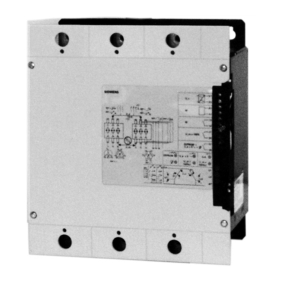
Page 18: Sikostart Controller Power And Motor Connections
Figure 12 - SIKOSTART Controller Power and Motor Connections Siemens Energy & Automation, Inc. - Page 19 When the DECEL TIMER is set to a value greater than zero, ramp 2 settings become decel settings and run #2 coil is not used. With DECEL TIMER = 0 the ramp 2 settings are for a second start ramp. Terminal Connections, Potentiometers, and Indicators Figure 13 - SIKOSTART Siemens Energy & Automation, Inc.
-
Page 20: Setup Controls
The SIKOSTART 3RW35 has two separately adjustable ramps, each having voltage and ramp settings. If the decel timer is set to a value other than zero, the second ramp is changed to a decel ramp, utilizing the soft stop capabilities of the SIKOSTART 3RW35. -
Page 21: Preliminary Checks
1. Temporarily remove run signal connections by opening the circuit at control terminals A1 and A2. 2. Turn on main AC power and control power to the controller; LED 1 comes on. Siemens Energy & Automation, Inc. -
Page 22: Motor Starting Adjustments
For a soft stop, most appli- cations require the stop time T2 to be equal to or longer than the start time T1. Turn run signal off before changing the T2 setting. Siemens Energy & Automation, Inc. -
Page 23: Electrical Specifications
Coil Voltage 120 VAC Isolation Voltage 1500 VAC Input Current 10mA@120VAC On Voltage 85 VAC max. On Current 6 mA min. Off Voltage 40 VAC max Off Current 3 mA min. 13k § Input Impedance Siemens Energy & Automation, Inc. - Page 24 * Fuse rating should not exceed 175% of full load motor rating for class RK1 and L fuses for Type 2 protection. Current Required (Milliamperes) Controller Current Rating 120V AC Control Voltage (Amperes) Control Fans 35, 57 69, 80, 105 131, 195, 248 480, 720, 960 Siemens Energy & Automation, Inc.
-
Page 25: Dimensions
1.24 0.25 (8) 3RW3586... 17 .62 28.32 8.68 3.99/ 0.91 25.71 1.13 0.25 (8) 5.44/ 5.44 3RW3584-.. Upper & Lower Mounting Hole Locations 3RW355- 3RW3586-.. Upper & Lower Mounting Hole Locations Figure 14 - Dimensions Siemens Energy & Automation, Inc. -
Page 26: Troubleshooting
Failure to properly maintain this equip- lems arise which are not covered sufficiently for the purchaser's ment can result in death, serious injury, purposes, the matter should be referred to the local Siemens property damage or product failure. sales office. - Page 27 If motor is coming up to speed too slowly, decrease Start Time T1 and/or increase Initial Voltage U; refer to paragraph 6.6. Shorted SCR (LED 4 Check SCR’s as described in paragraph 9.3. is on) Siemens Energy & Automation, Inc.
- Page 28 Check circuit breaker trip settings. Incorrect power wiring Check all power wiring connections to determine if a phase-to- causing a short on input or phase or phase-to-ground short is present. load side of controller Siemens Energy & Automation, Inc.
-
Page 29: Shorted Scr Checks
6. Battery clip and clip leads. control connection. Hazardous voltage. Will cause death or serious injury. To avoid electrical shock or burn, discon- nect and lock out all power sources from controller before testing. Siemens Energy & Automation, Inc. -
Page 30: Gate Triggering Test Diagram
4. Proceed to the other SCR in the module. Make the anode and cathode meter connections and measure for both polar- ities. 5. A short circuit or a measurement below one megohm prob- ably indicates a defective SCR. Siemens Energy & Automation, Inc. -
Page 31: Latching/Holding Test Diagram
1V. (See note above re batteries.) 7 . Disconnect all wires and meter. 8. Repeat above sequence on the second SCR in the module. Select between figures 18 through 20 which layout works best for the situation. Siemens Energy & Automation, Inc. -
Page 32: Typical Configurations
Figure 18 - for 3RW355*-.. Figure 19 - for 3RW356*-.. Figure 20 - Typical configurations Siemens Energy & Automation, Inc. -
Page 33: Spare And Optional Parts
480 - 720 3/Controller the fan on the left is the furthest from the control terminals. 3RW3960-8DC38 Similarly, when three fans are used, mounting locations are left (L), center (Ctr), and right (R). 3/Controller 3RW3960-8DC38 3RW3960-8DC38 Siemens Energy & Automation, Inc. - Page 34 3RW3958-7DC85 3RW3958-5DC84 3RW3958-5DC85 3RW3967-7DC84 3RW3967-7DC85 3RW3965-5DC84 3RW3965-5DC85 3RW3967-7DC84 3RW3967-7DC85 3RW3966-5DC84 3RW3966-5DC85 3RW3967-7DC84 3RW3967-7DC85 3RW3967-5DC84 3RW3967-5DC85 3/Controller 3/Controller 3/Controller 3/Controller 3RW3972-7DC84 3RW3972-7DC85 3RW3972-5DC84 3RW3972-5DC85 3RW3984-7DC84 3RW3984-7DC85 3RW3983-5DC84 3RW3983-5DC85 3RW3984-7DC84 3RW3984-7DC85 3RW3984-5DC84 3RW3984-5DC85 3RW3986-7DC84 3RW3986-7DC85 3RW3986-5DC84 3RW3986-5DC85 Siemens Energy & Automation, Inc.
-
Page 35: Optional Parts
10.2 Optional Parts Table 8 Lug Kits 10.2.1 Lug Kits Operational Lug Kit Hardware Table 7 lists lug kits for use with the SIKOSTART 3RW35 con- Current Part Torque Wire Size trollers. Each kit provides a method of adapting a controller for... - Page 36 Siemens Energy & Automation, Inc. 1000 McKee Street Batavia, IL 60510 Tel: 630/879-6000 Tel: 800/323-5450 http://www.siemens.com/controlsusa Publication No. SFIS-4503A-0600 © 2000 Siemens Energy & Automation, Inc. Subject to change without prior notice Siemens is a registered trademark of Siemens AG. Printed in the U.S.A.