Emerson Dixell XR70T Installing And Operating Instructions
Full touch
Hide thumbs
Also See for Dixell XR70T:
- Operating instructions manual (41 pages) ,
- Installing and operating instructions (40 pages) ,
- Quick reference manual (2 pages)
Table of Contents
Advertisement
Quick Links
Advertisement
Table of Contents

Related Manuals for Emerson Dixell XR70T


Summary of Contents for Emerson Dixell XR70T
- Page 1 XR70T – Full Touch (V.1.0)
-
Page 3: Table Of Contents
INDEX IMPORTANT USER INFORMATION ..................................5 PRODUCT DISPOSAL (WEEE) ....................................6 GENERALITIES ........................................7 USEFUL INFORMATION....................................7 USER INTERFACE ........................................7 SCREENS ........................................7 ICONS ........................................... 8 GESTURES ........................................10 HOME BROWSING ...................................... 10 STAND-BY MODE ......................................10 PROGRAMMING MENU ....................................10 SETPOINT MENU ...................................... - Page 4 13.6 EXTERNAL LOCK ALARM ( AL) ................................33 13.7 EXTERNAL PRESSURE ALARM ( F=PAL) ..............................33 13.8 EVAPORATOR FAN MODE ( F=FA ) ................................33 13.9 REMOTE HOLIDAY MODE ( F) ................................33 13.10 REMOTE ONOFF ( F) ..................................33 13.11 LIGHT OUTPUT ( G) .....................................
-
Page 5: Important User Information
1. IMPORTANT USER INFORMATION • symbol is intended to alert the user of a non-insultated voltage souce within the product area that is sufficiently high to constitute a risk of electric shock to persons. • symbol is intended to alert the user of important operating and maintenance (servicing) instructions. -
Page 6: Product Disposal (Weee)
• It is good practice to bear in mind the following indications for all Dixell products: Prevent the electronic circuits from getting wet as contact made with water, humidity or any other type of liquid can damage them. Comply with the temperature and humidity limits specified in the manual in order to store the product correctly. -
Page 7: Generalities
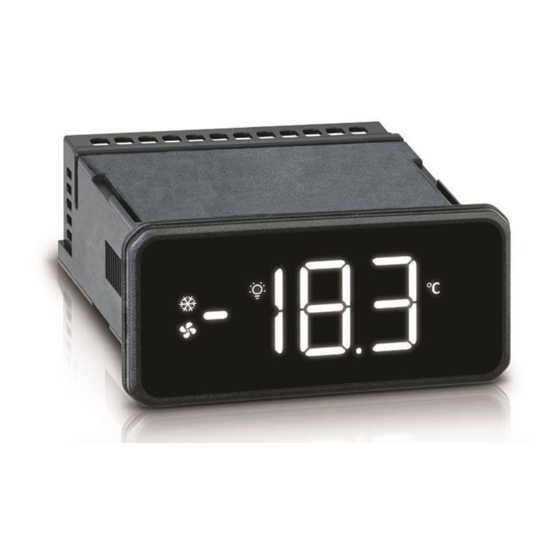
Full Touch technology. USEFUL INFORMATION Stay tuned on www.fulltouch.info CONTACT: dixell.service@emerson.com 4. USER INTERFACE XR70T has a capacitive user interface with Full Touch technology. The whole display area is used to interact with the device. Specific gestures are used to enable or disable... -
Page 8: Icons
Setpoint Menu: This screen enables the modification of the Set Point value. Parameter Menu: These screens enable the modification of all parameter values. Stand-By: in this condition all outputs are deactivated. HotKey Download: “PRG” blinks during download operations (copy from HotKey to the internal memory) HotKey Upload: “PRG”... - Page 9 When in the Virtual Keyboard screen: pull down OFF No alarm is active ALARM FLASH Some alarm is active Not used Celsius Degree FLASH Not used Measurement units: Celsius degree Not used Fahrenheit Degree FLASH Not used Measurement units: Fahrenheit degree FLASH ONOFF Only and always ON icon when the device is in standby mode...
-
Page 10: Gestures
GESTURES GESTURE NAME HOW-TO DESCRIPTION Switch ON / Switch OFF: when in Virtual Press a specific area Keyboard, use this to turn on/off a specific ONE TAP of the screen with a function. When in Programming mode, use this to finger for 1 sec select a parameter or a parameter value. -
Page 11: Setpoint Menu
SETPOINT MENU When in Programming Menu, it is possible to enter the Setpoint Menu by touching the SET icon for 3 sec. Both SET and PRG icons will blink until the Setpoint Menu is unlocked. Both PROG LEVEL icons start toggling to indicate that the visualized value is editable. -
Page 12: Parameter Menu
4.10 PARAMETER MENU When in Programmin Menu, it is possible to enter the Parameter Menu touching the PRG icon for 3 sec. The Prog Level 1 icon will indicate the first level of the programming menu (group labels). The Browsing icon will indicate that there are other groups of parameters. …... -
Page 13: Parameter Table
• Err if the password value is wrong After 2 sec the display will show the first group label (rEG) with a blinking PRG icon to indicate that protected parameters now are editable. 5. PARAMETER TABLE Here are the descriptions of the device parameters. PARAMETER DESCRIPTION 5.1.1 Main regulation parameters - rEG SEt Set Point: range from LS to US... -
Page 14: Defrost Configuration Parameters - Def
Remote probe displayed (for XH-REP): (P1; P2; P3; P4; SEt; dtr; USr) Px=probe “x”; SEt=set point; dtr=do not use it. Temperature display delay: (0.0 to 20min00sec, res. 10 sec) when the temperature increases, the display is updated of 1°C or 1°F after this time. Probe visualization percentage, F(P1;... -
Page 15: Auxiliary Regulator Parameters - Aus
Evaporator fan ON time in energy saving mode (with compressor OFF) (0 to 255 min) used when energy saving status is active. Evaporator fan OFF time in energy saving mode (with compressor OFF): (0 to 255 min) used when energy saving status is active. Evaporator fan delay: (0 to 255 sec) delay before activating evaporator fan Evaporator fan delay after closing door: (0 to 255 sec) delay before activating evaporator fan and after closing the door... -
Page 16: Digital And Analogue Output Configuration Parameters - Out
Pre-alarm threshold for second temperature alarm (absolute value): (-55.0 to 150.0°C; -67 to 302°F) Second high temperature pre-alarm differential: (0.1 to 25.0°C; 1 to 45°F) Second high temperature pre-alarm delay: (0 to 255 min; 255 = not used) delay time between the detection of a condenser pre-alarm condition and the relative alarm signalling. -
Page 17: Energy Saving Configuration Parameters - Es
Digital input 2 configuration: (nu; dor; dEF; AUS; ES; EAL; bAL; PAL; FAn; HdF; onF; LiG; CC; EMt) • nu = not used • dor = door switch function • dEF = defrost activation • AUS = auxiliary output • ES = energy saving mode activation •... -
Page 18: Real Time Clock Configuration Parameters - Rtc
Number of working hours for relay output oA2 (units of) Number of working hours for relay output oA3 (thousands of) Number of working hours for relay output oA3 (units of) Number of working hours for relay output oA4 (thousands of) Number of working hours for relay output oA4 (units of) 5.1.12 Real Time Clock configuration parameters - rtC Hours: 0 to 23 hours... -
Page 19: Parameter Configuration 1
Probe P4 value visualization Real regulation Set Point Firmware release date: day Firmware release date: month Firmware release date: year Firmware release: progressive number Firmware sub release: progressive number Parameter map version PARAMETER CONFIGURATION 1 Protec Group Par. Description Value U.O.M. - Page 20 Defrost mode rtC(0); in(1) Defrost type: electric heating, hot gas EL(0); in(1) nP(0); P1(1); P2(2); P3(3); Probe selection for defrost control P4(4) [-50.0°C to 50.0°C] End defrost temperature °C [-58.0°F to 122.0°F] Interval between two successive defrost 0 to 255 hours cycles Maximum length of defrost cycle 0 to 255 min...
- Page 21 [0.1°C to 25.0°C] Auxiliary regulator differential °C [0.1°F to 45.0°F] nP(0); P1(1); P2(2); P3(3); Probe selection for auxiliary regulator P4(4) Auxiliary regulator disabled during any n(0); Y(1) defrost cycle Base time for parameters Ato and AtF SEC; Min Interval of time with auxiliary output ON 0 to 255 sec/min Interval of time with auxiliary output OFF 0 to 255 sec/min...
- Page 22 nu(0); CP1(1); dEF(2); FAn(3); ALr(4); LiG(5); Relay output oA4 configuration AUS(6); db(7); onF(8); HES(9); Cnd(10); CP2(11); dF2(12); HEt (13); inv(14) Alarm relay polarity oP(0); CL(1) Base times for digital inputs SEC(0); Min(1) Digital input 1 polarity oP(0); CL(1) nu(0); dor(1); dEF(2); AUS(3);...
- Page 23 Number of working hours for relay hours read only output oA1 (thousands of) Number of working hours for relay hours read only output oA1 (units of) Number of working hours for relay hours read only output oA2 (thousands of) Number of working hours for relay hours read only output oA2 (units of)
-
Page 24: Parameter Configuration 2
9.6(0); 19.2(1); Baudrate 38.4(2); 57.6(3); Parity control no(0); odd(1); EvE(2) User interface timeout 1 to 255 sec Sound Level 0 to 5 Password for protected level Pr2 0 to 999 Probe P1 value visualization read only Probe P2 value visualization read only Probe P3 value visualization read only... - Page 25 Probe P4 presence n(0); Y(1) [-12.0°C to 12.0°C] Probe P4 calibration °F [-21.6°F to 21.6°F] Temperature measurement unit: °F °C(0); °F(1) Celsius; Fahrenheit Temperature resolution: decimal, dE(0); in(1) integer P1(0); P2(1); P3(2); Probe default displayed P4(3); SEt(4); dtr(5) P1(0); P2(1); P3(2); Remote probe displayed (for XH-REP) P4(3);...
- Page 26 Evaporator fan delay after closing door 0 to 255 sec Probe selection for condenser fan nP(0); P1(1); P2(2); P3(3); P4(4) Set Point 2 regulation (for condenser [-100.0°C to 150.0°C] 50.0 °F fan) [-148.0°F to 302.0°F] Set Point 2 differential (for condenser [0.1°C to 25.0°C] 20.0 °F...
- Page 27 Alarm relay deactivation n(0); Y(1) nu(0); CP1(1); dEF(2); FAn(3); ALr(4); LiG(5); AUS(6); db(7); Relay output oA2 configuration onF(8); HES(9); Cnd(10); CP2(11); dF2(12); HEt(13); inv(14) nu(0); CP1(1); dEF(2); FAn(3); ALr(4); LiG(5); AUS(6); db(7); Relay output oA3 configuration onF(8); HES(9); Cnd(10); CP2(11); dF2(12); HEt (13); inv(14) nu(0);...
- Page 28 Number of activations for relay output read only oA4 (units of) Number of total activations of digital read only input 1 (thousand of) Number of total activations of digital read only input 1 (units of) Number of total activations of digital read only input 2 (thousand of) Number of total activations of digital...
-
Page 29: Regulation
hh:m 5th defrost starting time 00:00 0.0 to 23h50min(143); nu(144) hh:m 6th defrost starting time 00:00 0.0 to 23h50min(143); nu(144) Current configuration C-1(0); C-2(1) Restore default factory setting n(0); Y(1) Reset Haccp values n(0); Y(1) Serial address 1 to 247 9.6(0);... -
Page 30: Parameters Involved
7.1.1 PARAMETERS INVOLVED • ErA: energy saving algorithm • i1F or i2F: set as door input to monitor the appliance usage • StE: interval to switch from normal to energy saving mode • EtS: interval to switch from energy saving to normal mode •... -
Page 31: Evaporator Fan And Digital Input
• HYF: differential • FnC: to define the working mode: C-n: in parallel with compressor output and stopped during any defrost. When compressor is OFF, they will start a duty-cycle mode (see FoF, Fon, FF1 and Fo1 parameters) O-n: always on, stopped during any defrost C-Y: in parallel with compressor output and always on during any defrost. -
Page 32: Auxiliary Output (Oax = Aus)
12.6 AUXILIARY OUTPUT (oAx = AUS) The auxiliary output can be managed by digital inputs (oAx=AUS, i1F or i2F=AUS): the output is switched on and off following the relative digital input status. 12.6.1 AUXILIARY REGULATOR The auxiliary regulator can be used to manage the auxiliary output. Here are the involved parameters: •... -
Page 33: Digital Inputs
13. DIGITAL INPUTS The digital inputs are programmable by using par. i1F and i2F. 13.1 DOOR SWITCH (ixF=dor) It signals the door status. Some relay outputs can be toggled depending on the odC parameter: • odC = no no change •... -
Page 34: Alarm Signalling
14. ALARM SIGNALLING Label Cause Outputs P1 probe failure Compressor output according to Con e CoF P2 probe failure Depends on the relative function P3 probe failure Depends on the relative function P4 probe failure Depends on the relative function High temperature alarm Outputs unchanged Low temperature alarm... -
Page 35: Wiring Diagram
17. WIRING DIAGRAM Power Supply: 110VAC, 230VAC or 100-240VAC, 50-60Hz oA1: always set as main compresso output (CP1) 1592040000 XR70T EN v1.1 2019.07.09 XR70T 35/40... -
Page 36: Technical Specifications
18. TECHNICAL SPECIFICATIONS FEATURES DESCRIPTION Housing Self-extinguishing PC Dimensions Front fascia 38x80 mm; case depth 81mm Mounting Panel mounting, 71x29mm panel cut-out Protection Body: IP20; Front: IP66 230Vac 10%, 50/60Hz; 110Vac 10%, 50/60Hz; 100 to 240VAC10%, 50/60Hz; 12VAC 10% Power Supply Overvoltage category II Rated Power 12VAC: 3VA;... -
Page 37: Appendix
19. APPENDIX 19.1 TOOLS 19.1.1 XH-REP The XH-REP remote display enables the visualization of a second temperature value. A special cable must be used to connect an XH-REP to the controller (code DD200002 00). The remote display usage will disable the serial communication. -
Page 38: Example Of Menu Navigation And Parameter Modification
19.2 EXAMPLE OF MENU NAVIGATION AND PARAMETER MODIFICATION TAP and HOLD PRESS “PRG” TAP and HOLD “PRG” TAP and HOLD “PRG” H-SWIPE to browse V-SWIPE to modify (…) TAP and HOLD “PRG” to save and exit and exit icons are blinking 1592040000 XR70T EN v1.1 2019.07.09 XR70T 38/40... - Page 39 1592040000 XR70T EN v1.1 2019.07.09 XR70T 39/40...
- Page 40 1592040000 XR70T EN v1.1 2019.07.09 XR70T 40/40...