Table of Contents
Advertisement
Advertisement
Table of Contents

Related Manuals for Gigabyte Z370 AORUS Ultra Gaming


Summary of Contents for Gigabyte Z370 AORUS Ultra Gaming
- Page 1 Z370 AORUS Ultra Gaming User's Manual Rev. 1002 12ME-Z37AULG-1002R For more product details, please visit GIGABYTE's website. To reduce the impacts on global warming, the packaging materials of this product are recyclable and reusable. GIGABYTE works with you to protect the environment.
- Page 2 The trademarks mentioned in this manual are legally registered to their respective owners. Disclaimer Information in this manual is protected by copyright laws and is the property of GIGABYTE. No part of this manual may be reproduced, copied, translated, transmitted, or published in any form or by any means without GIGABYTE's prior written permission.
-
Page 3: Table Of Contents
Table of Contents Z370 AORUS Ultra Gaming Motherboard Layout ............4 Chapter 1 Hardware Installation ..................5 Installation Precautions ..................5 ..................6 Installing the CPU ..................10 Installing the Memory ..................10 Installing an Expansion Card ................. 11 Setting up AMD CrossFire ™... -
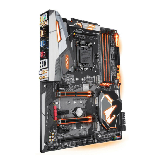
Page 4: Z370 Aorus Ultra Gaming Motherboard Layout
Z370 AORUS Ultra Gaming Motherboard Layout ATX_12V_2X4 KB_MS_USB30 CPU_FAN SYS_FAN1 CPU_OPT LGA1151 ASMedia ® USB 3.1 Gen 2 Controller USB_LAN AUDIO PCIEX1_1 Z370 AORUS Ultra Gaming PCIEX16 Intel ® PCIEX1_2 THB_C Intel Z370 ® ® Super I/O PCIEX8 CODEC PCIEX1_3... -
Page 5: Chapter 1 Hardware Installation
Chapter 1 Hardware Installation Installation Precautions The motherboard contains numerous delicate electronic circuits and components which can become damaged as a result of electrostatic discharge (ESD). Prior to installation, carefully read the user's manual and follow these procedures: Prior to installation, make sure the chassis is suitable for the motherboard. Prior to installation, do not remove or break motherboard S/N (Serial Number) sticker or warranty sticker provided by your dealer. - Page 6 Support for DDR4 2666/2400/2133 MHz memory modules Support for ECC Un-buffered DIMM 1Rx8/2Rx8 memory modules (operate in non-ECC mode) Support for non-ECC Un-buffered DIMM 1Rx8/2Rx8/1Rx16 memory modules (Go to GIGABYTE's website for the latest supported memory speeds and memory modules.) ® Onboard...
- Page 7 Storage Chipset: 1 x M.2 connector (Socket 3, M key, type 2242/2260/2280/22110 PCIe x4/ Interface x2 SSD support) (M2Q_32G) 1 x M.2 connector (Socket 3, M key, type 2242/2260/2280 SATA and PCIe x4/x2 SSD support) (M2A_32G) 6 x SATA 6Gb/s connectors Support for RAID 0, RAID 1, RAID 5, and RAID 10 * Refer to "1-8 Internal Connectors,"...
- Page 8 Back Panel 1 x PS/2 keyboard/mouse port 1 x DVI-D port Connectors 1 x HDMI port ™ 1 x USB Type-C port, with USB 3.1 Gen 2 support 1 x USB 3.1 Gen 2 Type-A port (red) 4 x USB 3.1 Gen 1 ports 2 x USB 2.0/1.1 ports 1 x RJ-45 port 1 x optical S/PDIF Out connector...
- Page 9 ATX Form Factor; 30.5cm x 24.4cm without prior notice. Please visit GIGABYTE's website Please visit the Support\Utility List for support lists of CPU, memory page on GIGABYTE's website to modules, SSDs, and M.2 devices. download the latest version of apps. - 9 -...
-
Page 10: Installing The Cpu
Make sure that the motherboard supports the memory. It is recommended that memory of the same capacity, brand, speed, and chips be used. (Go to GIGABYTE's website for the latest supported memory speeds and memory modules.) Always turn off the computer and unplug the power cord from the power outlet before installing the memory to prevent hardware damage. -
Page 11: Installing An Expansion Card
The four memory sockets are divided into two channels and each channel has two memory sockets as following: Channel A: DDR4_2, DDR4_4 Channel B: DDR4_1, DDR4_3 DDR4_4 DDR4_2 DDR4_3 DDR4_1 2 Modules DS/SS DS/SS DS/SS DS/SS 4 Modules DS/SS DS/SS DS/SS DS/SS (SS=Single-Sided, DS=Double-Sided, "- -"=No Memory) -
Page 12: Back Panel Connectors
Back Panel Connectors PS/2 Keyboard/Mouse Port Use this port to connect a PS/2 mouse or keyboard. USB 3.1 Gen 1 Port (Note) DVI-D Port (the actual resolutions supported depend on the monitor being used). Connect a monitor that supports DVI-D connection to this port. USB 3.1 Gen 2 Type-A Port (Red) ™... - Page 13 If you want to install a Side Speaker, you need to retask either the Line in or Mic in jack to be Side Speaker out using the HD Audio Manager application. Please visit GIGABYTE's website for more audio software information. device and then remove it from the motherboard.
-
Page 14: Internal Connectors
Internal Connectors 13 8 12 20 22 ATX_12V_2X4 F_PANEL F_AUDIO CPU_FAN SPDIF_O SYS_FAN1/2A/2B F_USB30C SYS_FAN3_PUMP F_USB30 CPU_OPT F_USB1/F_USB2 LED_C1/LED_C2 D_LED1/D_LED2 THB_C DLED_V_SW1/DLED_V_SW2 CLR_CMOS SATA3 0/1/2/3/4/5 M2Q_32G/M2A_32G CPU/VGA/DRAM/BOOT Read the following guidelines before connecting external devices: First make sure your devices are compliant with the connectors you wish to connect. Before installing the devices, be sure to turn off the devices and your computer. - Page 15 1/2) ATX_12V_2X4/ATX (2x4 12V Power Connector and 2x12 Main Power Connector) With the use of the power connector, the power supply can supply enough stable power to all the components off and all devices are properly installed. The power connector possesses a foolproof design. Connect the power supply cable to the power connector in the correct orientation.
- Page 16 5) SYS_FAN3_PUMP (System Fan/Water Cooling Pump Header) The fan/pump header is 4-pin and possesses a foolproof insertion design. Most fan headers possess a foolproof insertion design. When connecting a fan cable, be sure to connect it in the correct orientation (the black connector wire is the ground wire).
- Page 17 8) D_LED1/D_LED2 (Digital LED Strip Headers) The headers can be used to connect a standard 5050 digital LED strip, with maximum power rating of 2A (12V or 5V) and maximum length of 5m or maximum number of 300 LEDs. Pin No. D_LED1 D_LED2 Connect your digital LED strip to the header.
- Page 18 11) M2Q_32G/M2A_32G (M.2 Socket 3 Connectors) note that an M.2 PCIe SSD cannot be used to create a RAID set either with an M.2 SATA SSD or a SATA M2Q_32G M2A_32G Follow the steps below to correctly install an M.2 SSD in the M.2 connector. Step 1: Use a screw driver to unfasten the screw and nut from the motherboard.
- Page 19 12) F_PANEL (Front Panel Header) Connect the power switch, reset switch, speaker, chassis intrusion switch/sensor and system status indicator on the chassis to this header according to the pin assignments below. Note the positive and negative pins before connecting the cables. PLED/PWR_LED (Power LED, Yellow/Purple): Power LED Power Switch...
- Page 20 14) SPDIF_O (S/PDIF Out Header) This header supports digital S/PDIF Out and connects a S/PDIF digital audio cable (provided by expansion cards) for digital audio output from your motherboard to certain expansion cards like graphics cards and sound cards. For example, some graphics cards may require you to use a S/PDIF digital audio cable for digital audio output from your motherboard to your graphics card if you wish to connect an HDMI display to the graphics card and have digital audio output from the HDMI display at the same time.
- Page 21 Pin No. Pin No. LAD0 LAD3 VCC3 LAD1 LFRAME No Pin LAD2 SERIRQ LCLK LRESET 19) THB_C (Thunderbolt ™ Add-in Card Connector) This connector is for a GIGABYTE Thunderbolt ™ add-in card. Supports a Thunderbolt ™ add-in card. - 21 -...
- Page 22 20) CLR_CMOS (Clear CMOS Jumper) the CMOS values, use a metal object like a screwdriver to touch the two pins for a few seconds. Open: Normal Short: Clear CMOS Values Always turn off your computer and unplug the power cord from the power outlet before clearing the CMOS values.
-
Page 23: Chapter 2 Bios Setup
To access the BIOS Setup program, press the <Delete> key during the POST when the power is turned on. To upgrade the BIOS, use either the GIGABYTE Q-Flash or @BIOS utility. Q-Flash allows the user to quickly and easily upgrade or back up BIOS without entering the operating system. - Page 24 M.I.T. Whether the system will work stably with the overclock/overvoltage settings you made is dependent on your overall and reduce the useful life of these components. This page is for advanced users only and we recommend you not to alter the default settings to prevent system instability or other unexpected results. (Inadequately altering the settings may result in system's failure to boot.
- Page 25 Advanced CPU Core Settings The settings above are synchronous to those under the same items on the Advanced Frequency Settings menu. (Note) AVX Offset AVX offset is the negative offset of AVX ratio. Uncore Ratio Allows you to set the CPU Uncore ratio. The adjustable range is dependent on the CPU being used. Uncore Frequency Displays the current CPU Uncore frequency.
- Page 26 C3 State Support (Note) Allows you to determine whether to let the CPU enter C3 mode in system halt state. When enabled, the CPU core frequency and voltage will be reduced during system halt state to decrease power consumption. The C3 state is a more enhanced power-saving state than C1. Auto this setting.
- Page 27 (Note) Allows the BIOS to read the SPD data on XMP memory module(s) to enhance memory performance when enabled. Disabled Disables this function. (Default) (Note) System Memory Multiplier Allows you to set the system memory multiplier. Auto sets memory multiplier according to memory SPD data.
- Page 28 Memory Multiplier Tweaker Provides different levels of memory auto-tuning. (Default: Auto) Channel Interleaving Enables or disables memory channel interleaving. Enabled allows the system to simultaneously access different channels of the memory to increase memory performance and stability. Auto lets the BIOS Rank Interleaving Enables or disables memory rank interleaving.
- Page 29 CPU Vcore/CPU VCCSA/DRAM Channel A/B Voltage/+3.3V/+5V/+12V/CPU VAXG Displays the current system voltages. Miscellaneous Settings Max Link Speed Allows you to set the operation mode of the PCI Express slots to Gen 1, Gen 2, or Gen 3. Actual operation Auto setting.
-
Page 30: System
System This section provides information on your motherboard model and BIOS version. You can also select the default language used by the BIOS and manually set the system time. Access Level Displays the current access level depending on the type of password protection used. (If no password is set, the default will display as Administrator.) The Administrator level allows you to make changes to all BIOS settings;... -
Page 31: Bios
A password is required for booting the system and for entering the BIOS Setup program. (Default) Full Screen LOGO Show Allows you to determine whether to display the GIGABYTE Logo at system startup. Disabled skips the GIGABYTE Logo when the system starts up. (Default: Enabled) Boot Option Priorities... - Page 32 SATA Support Last Boot HDD Only Except for the previous boot drive, all SATA devices are disabled before the OS boot process completes. All Sata Devices All SATA devices are functional in the operating system and during the POST. (Default) Fast Boot is set to Enabled or Ultra Fast.
- Page 33 Other PCI devices Allows you to select whether to enable the UEFI or Legacy option ROM for the PCI device controller other than the LAN, storage device, and graphics controllers. Do not launch Disables option ROM. UEFI Enables UEFI option ROM only. (Default) Legacy Enables legacy option ROM only.
-
Page 34: Peripherals
Peripherals Initial Display Output graphics. EZ RAID Above 4G Decoding Enables or disables 64-bit capable devices to be decoded in above 4 GB address space (only if your system supports 64-bit PCI decoding). Set to Enabled if more than one advanced graphics card are installed and their drivers are not able to be launched when entering the operating system (because of the limited 4 GB memory address space). - Page 35 Intel Platform Trust Technology (PTT) Enables or disables Intel ® PTT Technology. (Default: Disabled) SW Guard Extensions (SGX) Enables or disables the Intel ® Software Guard Extensions technology. This feature allows legal software to operate in a safe environment and protects the software against attacks from malicious software. The Software Controlled option allows you to enable or disable this feature with an Intel-provided application.
- Page 36 Displays information on your M.2 NVME PCIe SSD if installed. Legacy USB Support Allows USB keyboard/mouse to be used in MS-DOS. (Default: Enabled) XHCI Hand-off Determines whether to enable XHCI Hand-off feature for an operating system without XHCI Hand-off support. (Default: Disabled) USB Mass Storage Driver Support Enables or disables support for USB storage devices.
-
Page 37: Chipset
Chipset VT-d (Note) ® Enables or disables Intel Virtualization Technology for Directed I/O. (Default: Enabled) Internal Graphics Enables or disables the onboard graphics function. (Default: Auto) DVMT Pre-Allocated Allows you to set the onboard graphics memory size. Options are: 32M~1024M. (Default: 64M) DVMT Total Gfx Mem Allows you to allocate the DVMT memory size of the onboard graphics. -
Page 38: Power
Power Platform Power Management Enables or disables the Active State Power Management function (ASPM). (Default: Disabled) PEG ASPM Platform Power Management is set to Enabled. (Default: Enabled) PCH ASPM Platform Power Management is set to Enabled. (Default: Enabled) DMI ASPM Platform Power Management is set to Enabled. - Page 39 Power On Password Set the password when Power On By Keyboard is set to Password. Press <Enter> on this item and set a password with up to 5 characters and then press <Enter> to accept. To turn on the system, enter the password and press <Enter>. Note: To cancel the password, press <Enter>...
-
Page 40: Save & Exit
Save & Exit Save & Exit Setup Press <Enter> on this item and select Yes. This saves the changes to the CMOS and exits the BIOS Setup program. Select No or press <Esc> to return to the BIOS Setup Main Menu. Exit Without Saving Press <Enter>... -
Page 41: Chapter 3 Appendix
Chapter 3 Appendix RAID Levels RAID 0 RAID 1 RAID 5 RAID 10 Minimum Number of Hard Drives Array Capacity Number of hard Size of the smallest (Number of hard (Number of hard drives * Size of the drive drives -1) * Size of drives/2) * Size of the smallest drive the smallest drive... - Page 42 Steps: 1. In BIOS Setup, go to BIOS and set CSM Support to Disabled. Save the changes and exit BIOS Setup. 2. After the system reboot, enter BIOS Setup again. Then enter the Peripherals\Intel(R) Rapid Storage Technology sub-menu. 3. On the Intel(R) Rapid Storage Technology menu, press <Enter> on Create RAID Volume to enter the Create RAID Volume screen.
-
Page 43: Installing An Intel Optane Memory
Installing the SATA RAID/AHCI Driver and Operating System With the correct BIOS settings, you are ready to install the operating system. Installing the Operating System ® As some operating systems already include Intel SATA RAID/AHCI driver, you do not need to install separate RAID/AHCI driver during the Windows installation process. - Page 44 A-2: Installation in Intel RST Premium With Intel Optane System Acceleration mode please follow the steps below: 1. After system restarts, go to the BIOS Setup, make sure CSM Support under the BIOS menu is disabled. 2. Go to and make sure Use RST Legacy OROM is disabled. If ™...
-
Page 45: Drivers Installation
You can click the Xpress Install button and "Xpress Install" will install all of the selected drivers. Or click the arrow icon to individually install the drivers you need. Please visit GIGABYTE's website for more software information. - 45 -... -
Page 46: Regulatory Statements
Contravention will be prosecuted. We believe that the information contained herein was accurate in all respects at the time of printing. GIGABYTE cannot, however, assume any responsibility for errors or omissions in this text. Also note that the information in this document is subject to change without notice and should not be construed as a commitment by GIGABYTE. - Page 47 FCC Notice (U.S.A. Only) This equipment has been tested and found to comply with the limits for a Class B digital device, pursuant to Part 15 of the FCC Rules. These limits are designed to provide reasonable protection against harmful interference in a residential installation.
-
Page 48: Contact Us
Contact Us Address: No.6, Baoqiang Rd., Xindian Dist., New Taipei City 231, Taiwan TEL: +886-2-8912-4000, FAX: +886-2-8912-4005 Tech. and Non-Tech. Support (Sales/Marketing) : http://esupport.gigabyte.com WEB address (English): http://www.gigabyte.com WEB address (Chinese): http://www.gigabyte.tw GIGABYTE eSupport To submit a technical or non-technical (Sales/Marketing) question, please link to: http://esupport.gigabyte.com...