
Related Manuals for Hilti D-LP 30


Summary of Contents for Hilti D-LP 30
- Page 1 *315414* D-LP 30 / DS-TS 30, D-LP 20 / DS-TS 30 315414 Wall saw system Operating instructions...
-
Page 2: Table Of Contents
Congratulations! In purchasing the Hilti D-LP 30 (LP 20) / DS-TS 30 wall saw system you have acquired a quality product that provides the highest level of performance, safety and reliability. Uncompromising quality assurance during its manufacture ensures that the system will have a long service life. -
Page 3: General Warnings
Make sure sufficient space is available for working safely. Use metal anchors (size M12) for fastening DS-RF rail supports and DS-RFP angular cutting plates. Secure fas- tenings of a type suitable for the material being cut must be installed, e.g. Hilti HKD-D, HSA-A, HIT, HEA / HAS anchors. -
Page 4: General Safety Precautions
DS-CB 3 or DS-CB 4 remote control unit. 2.14 When auxiliary saw systems such as the Hilti DS-WSS 30 wire saw are used, the information contained in the applicable supplementary operating instructions must be observed. - Page 5 3.15 If, for whatever reason, it is found that the hydraulic unit does not switch off, set the controls to the neutral posi- tion (idling) and simply pull out the mains plug. 3.16 If an electric generator is used to power the D-LP 30 (LP 20) hydraulic unit, it must provide an output of at least 40 kVA and must be earthed/grounded.
- Page 6 3.21 Saw blade speeds: Adhere to the recommended speeds (r.p.m.) for each blade diameter (please refer to section 6.2). 3.22 Information required when transporting the hydraulic unit and saw head: D-LP 30 (LP 20) DS-TS 30 in transport box L×W×H = 700×530×1140 LxWxH = 610×410×450...
- Page 7 4. The D-LP 30 (LP 20) / DS-TS, PS, WSS modular saw system D-LP30 (LP20) – DS-TS 30 DS-BG H DS-BGF H 800 - 1600 mm 800 - 1600 mm D-PH34-10 (2x)H D-FH4/14-10 D-PH58-10 (2x)H D-FH14 D-PH58-10 (2x) D-CO-ML D-R 50-230L...
-
Page 8: General Description And Technical Data
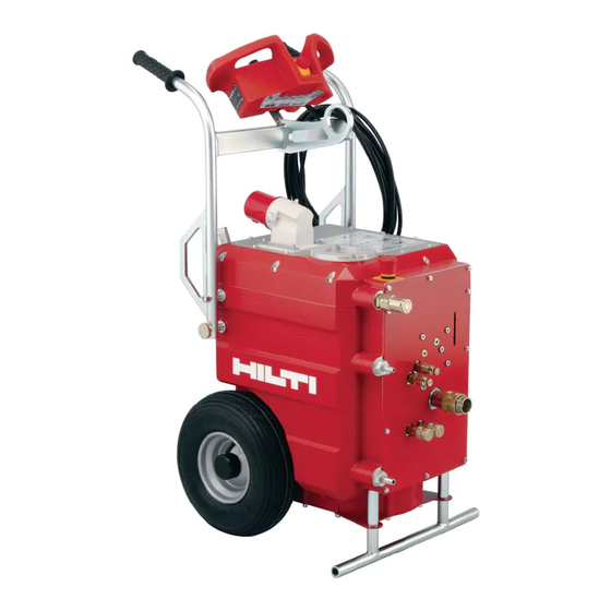
5. General description and technical data for the D-LP 30 (LP 20) / DS-TS 30 The D-LP 30 (LP 20) / DS-TS 30 is a medium- to heavy-duty, high-performance wall saw system for use with saw blades of up to 1600 mm dia. It is capable of cutting to a depth of 73 cm. The saw system is extremely convenient, can be assembled and operated quickly and easily by one man and provides optimal cutting performance at all times. - Page 9 30-50 m/sec. may be used. Recommended speed and gear (r.p.m. under load) - guide values The guide values below are printed on the cover of the D-LP 30 (LP 20) and on the DS-CB 3 / CB-4 remote con- trol unit.
- Page 10 Direction of rotation of the motor or saw blade. ³ » ¿ ¶ · Low 1 gear High 2 gear ´ ² 180° 180° Maintenance Keep the gear change mechanism clean and lubricate it with Hilti spray at weekly intervals.
- Page 11 Saw blades - the Hilti DS-BR saw blade programme – The quality of the saw blade and selection of the correct type of blade is decisive. The Hilti DS-BR blade types BC and LC have been designed for use with the DS-TS 30 and other equipment of a similar power rating. They...
-
Page 12: Preparing The Workplace And Saw System
LP30/400V LP30/400V * maximum cable length in metres CEE 63 plug on the D-LP 30 (LP 20) – pin assignement LP 30, 400 V, 3 phases + N + PE LP 20, 230 V, 3 phases + PE 9 h... -
Page 13: Setting Up The Saw System For Various Applications
Observe the installation instructions given by the anchor manufacturer for setting the anchors. – For example, when placing the Hilti HKD M12 metal expansion anchor, a minimum distance of 18 cm to the nearest edge must be observed. As a rule, the concrete dust should be blown out of the hole and the anchors set >... - Page 14 – When mounting the rails, always position the rail support at right angles to the rail and then tighten all rail fas- tening screws securely. – All Hilti D-R..L rails can be extended to form a rigid unit by making use of a tapered connector: D-C-O-ML double taper, item no. 232241/0, eccentric pin, item no. 231244/4.
- Page 15 Mounting the DS-TS30-54 and DS-TS30-45 saw head, hydraulic hoses and saw blade ³ – The saw arm should be in the starting position (vertically » upwards). Press the release buttons with the thumbs and pivot the ∅ 120 mm · grips through approx.
- Page 16 258436/5. It will permit more rapid progress and help prevent back injuries caused by lifting heavy loads. 424 mm – The Hilti saw system can be preassembled and positioned precisely, to the millimetre. – The electric remote control system permits the saw arm to be pivot- ed effortlessly into position in the saw blade.
- Page 17 – The user carries the responsibility for ensuring that the control system employed functions correctly. – The Hilti D-RC 30 remote control unit, item no. 312891/5, may be used. (The stand for this unit is the D-RS15, item no. 221269/4.)
- Page 18 * Largest initial diameter, Main application, Possible application * 500 mm dia. drive pulley for the Hilti DS-WSS 30 wire saw system, unlimited cutting depth in metres (m) TS 30 remaining distances TS 30 remaining distances TS 30 remaining distance B (cm) TS 30 remaining distance A (cm) (cm) 800 dia.
- Page 19 – If the D-LP 30 does not start or shuts down again immediately, the reason may be that the oil level is too low (top up) or the unit has overheated due to inadequate cooling.
- Page 20 DS-CB 3 / CB 4 electric remote control unit set to the “O” (off) or neu- tral position. 10.2 Operation of the D-LP 30 (LP 20) using the DS-CB 3/CB 4 remote control The DS-CB 3 / CB 4 electric remote control unit provides the operator with the optimum means of control at all times.
- Page 21 This happens from time to time. The safety system is activated immediately (the pressure release valve on the D-LP 30 (LP 20) is set to 210 bar). This situation presents no risk to the operator or the saw system. The operator should react by reversing the direction of advance.
-
Page 22: Dismantling The Saw System
– The guide rollers and cam-action rollers should be kept clean and lubricated with Hilti oil spray. – Clean the gear change mechanism at the saw blade spindle at weekly intervals and lubricate it with Hilti oil spray. – These instructions apply to all Hilti saw heads. - Page 23 Electric power and water are connected, the DS-CB 3 / CB 4 remote control unit is connected, all hydraulic hoses are connected and the saw system is assembled and ready to begin sawing. The D-LP 30 (LP 20) hydraulic unit refuses to start.
- Page 24 LP30 doest not – Printed circuit board, – Consult a Hilti specialist start item no. 242231/9, possibly – Replace the printed circuit board defective or out of adjustment – Use the diagnostic equipment to...
- Page 25 – Unscrew bottom cover, check does not react motor to the pump is defective drive belt and replace if correctly necessary (Hilti specialist) 11 LP 30 starts but – Electro-hydraulic switching – Unscrew LP 30 front cover the saw head...
- Page 26 Check Problem Possible cause Solution / action required 17 Water or oil – Water seal defective – Check at the radial hole in the saw leakage at the – Oil seal defective blade flange saw arm drive – Have the saw head serviced flange 13.3 Hydraulic unit or saw system overheats / drop in performance Check Problem...
- Page 27 Check Problem Possible cause Solution / action required Gear 19 Operator – Saw blade running at too high – Observe recommended oil flow rate Pos. speed = r.p.m. Ø 1600 1500 1200 1000 Gear Pos. Ø Pos. Max.1 Important safety information Adhere to the recommended speed (r.p.m.) settings.
-
Page 28: Warranty
14. Warranty Hilti warrants that the product supplied is free of defects in material and workmanship. This warranty is valid as long as the tool is operated and handled correctly, cleaned and serviced properly and in accordance with the Hilti operating instructions, all warranty claims are made within 12 months from the date of sale (invoice date), and the technical sys- tem is maintained. - Page 29 ”Verwenden Sie das Produkt in keinem Fall anders, ”Não utilizar este produto a não ser para os fins a als es diese Bedienungsanleitung vorschreibt.” que está destinado por este manual de instruções.” Geräusch- und Vibrationswerte Ruído e vibração Typische A-bewertete Schallpegel des Gerätes sind: Caracteristicamente os níveis de ruído A medidos da ferramenta são: -Schalldruckpegel: 190 dB(A)
- Page 30 Suunnitteluvuosi: 1997 Todistamme täten ja vastaamme yksin siitä, että tämä tuote en allalueteltujen standardien ja stan- dardoimisasiakirjojen vaatimusten mukainen: EN 60204-1, EN 55014-1, EN 55014-2 seuraavien ohjeiden määräysten mukaisesti: 73/23/EWG, Hilti Corporation 89/336/EWG, 98/37/EG CE Δηλωση συμδατικοτητος Περιγραφή: Υδραυλική Μονάδα...
- Page 32 Tel.: +423 / 236 2111 Fax: +423 / 236 29 65 www.hilti.com Hilti = registered trademark of Hilti Corp., Schaan W 2220 0201 0,2-e 1 Printed in Liechtenstein © 2001 Right of technical and programme changes reserved S.E.&O. 315414/3 B...