Icom IC-A110 Instruction Manual
Vhf air band transceiver
Hide thumbs
Also See for IC-A110:
- Service manual (38 pages) ,
- Instruction manual (24 pages) ,
- Price list (158 pages)

Related Manuals for Icom IC-A110


Summary of Contents for Icom IC-A110
- Page 1 INSTRUCTION MANUAL VHF AIR BAND TRANSCEIVER iA110 This device complies with Part 15 of the FCC Rules. Operation is subject to the condition that this device does not cause harmful interference.
-
Page 2: Foreword
This connection will not only blow fuses but also may damage the transceiver. Icom, Icom Inc. and the logo are registered trademarks of Icom Incor- DO NOT place unit in a non-secure place to avoid inad- porated (Japan) in the United states, the United Kingdom, Germany, France, vertent use by children. -
Page 3: Table Of Contents
FCC caution: Changes or modifications to this transceiver, not 9 OPC-871 HEADSET ADAPTER........17–18 I OPC-871 Headset adapter ..............17 expressly approved by Icom Inc., could void your authority to 10 OPTIONS ................19 operate this transceiver under FCC regulations. -
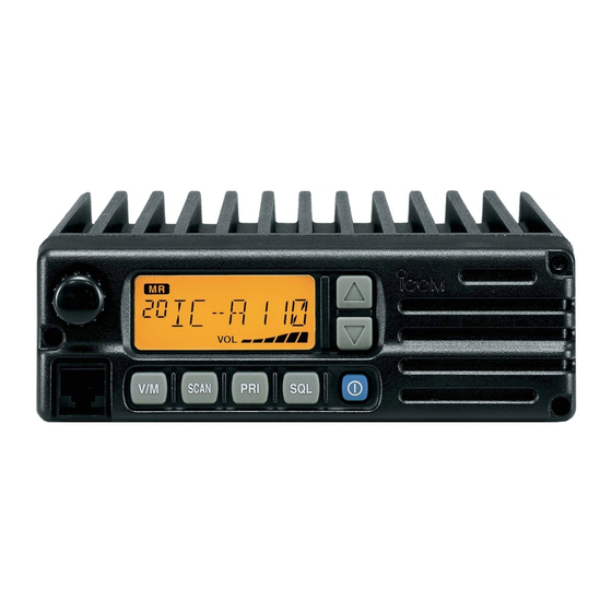
Page 4: Panel Description
PANEL DESCRIPTION I Panel description SCAN q TUNING [DIAL(TS)] e VOLUME UP [Y] DOWN [Z] KEY ➥ Changes the operating frequency; memory channel in Adjusts the audio output level. memory mode; set mode contents in set mode, etc. ➥ Push to toggle the dimmer control OFF, Low and High. r LOUD SPEAKER ➥... - Page 5 PANEL DESCRIPTION y SQL SWITCH [SQL] !0 MICROPHONE CONNECTOR ➥ Push to turn on the squelch adjust mode. (p. 6) Connects the supplied microphone or optional. ➥ Push and hold this switch for 1 sec. to turn ON/OFF the NEVER connect other microphones. The pin assignments both internal and external speaker output.
-
Page 6: I Function Display
PANEL DESCRIPTION I Function display t TX INDICATOR (p. 5) Appears while transmitting. y FREQUENCY DISPLAY (p. 11) ➥Shows the operating frequency. ➥Shows the channel name when the memory name function is selected. (p. 10) u VOLUME LEVEL INDICATORS ... -
Page 7: Basic Operation
BASIC OPERATION I Power ON I Channel selection ï VFO/Memory selection q Push [POWER] to turn power ON. q Push [V/M] to select memory mode or VFO mode. ➥ Rotate the dial to select a de- sired frequency/channel. w During memory mode opera- w Operate the transceiver as indicated in the following sec- tion, push the [V/M] key to transfer the memory contents... -
Page 8: I Squelch Function
A-5616H-1EX-e Printed in Japan 1999–2008 Icom Inc. © 1-1-32 Kamiminami, Hirano-ku, Osaka 547-0003, Japan Printed on recycled paper with soy ink.