Icom IC-A110EURO Instruction Manual
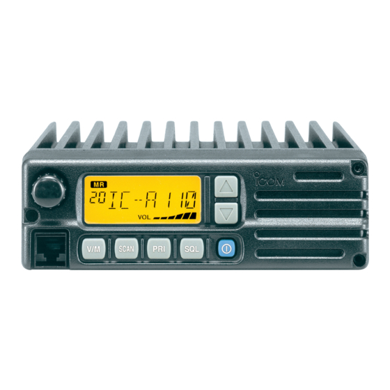
Vhf air band transceiver
Hide thumbs
Also See for IC-A110EURO:
- Instruction manual (24 pages) ,
- Service manual addendum (79 pages)
Table of Contents
Advertisement
Quick Links
Advertisement
Table of Contents

Related Manuals for Icom IC-A110EURO


Summary of Contents for Icom IC-A110EURO
- Page 1 INSTRUCTION MANUAL VHF AIR BAND TRANSCEIVER iA110EURO...
-
Page 2: Foreword
This connection will not only blow fuses but also may damage the transceiver. Icom, Icom Inc. and Icom logo are registered trademarks of Icom In- DO NOT place unit in a non-secure place to avoid inad- corporated (Japan) in Japan, the United States, the United King- dom, Germany, France, Spain, Russia and/or other countries. -
Page 3: Table Of Contents
TABLE OF CONTENTS DO NOT FOREWORD ..................i push [PTT] when not actually desiring to trans- EXPLICIT DEFINITIONS ................ i mit. CAUTIONS ..................... i TABLE OF CONTENTS ................ii DO NOT PANEL DESCRIPTION ............. 1 – 3 use or place the transceiver in direct sunlight or ■... -
Page 4: Panel Description
PANEL DESCRIPTION ■ Panel description SCAN q TUNING [DIAL] [TS](DIAL) e VOLUME UP [Y] DOWN [Z] KEY Adjusts the audio output level. ➥ Changes the operating frequency; memory channel in the Memory mode; set mode contents in the Set mode, r LOUD SPEAKER etc. - Page 5 PANEL DESCRIPTION y SQL SWITCH [SQL] !0 MICROPHONE CONNECTOR ➥ Push to turn ON the squelch adjust mode. (p. 6) Connects to the supplied microphone or optional. NEVER connect other microphones. The pin assignments ➥ Hold down this switch for 1 second to turn the both in- ternal and external speaker output ON or OFF.
-
Page 6: Function Display
PANEL DESCRIPTION ■ Function display t TX INDICATOR (p. 5) Appears while transmitting. y FREQUENCY DISPLAY (p. 11) ➥Shows the operating frequency. ➥Shows the channel name when the memory name function is selected. (p. 10) u VOLUME LEVEL INDICATORS ➥ Shows the AF volume level (while receiving). i SET MODE INDICATOR ➥... -
Page 7: Basic Operation
BASIC OPERATION ■ Power ON ■ Channel selection q Push [POWER] to turn ON the power. ï VFO/Memory selection Push [V/M] to select the Mem- ory mode or the VFO mode. ➥ Rotate [DIAL] to select a de- sired frequency or channel. w Operate the transceiver as described in the following sec- tions. -
Page 8: Squelch Function
BASIC OPERATION ■ Squelch function ■ Dial select function The transceiver has a noise squelch circuit to mute unde- Use the dial select function to adjust the tuning step of the sired noise while receiving no signals. [DIAL] keys. Use 1 MHz tuning when you want to change the frequency in large increments;... -
Page 9: Scan Operation
SCAN OPERATION ■ Scan operation • VFO scan R e p e a t e d l y s c a n s a l l frequencies over the entire lowest highest q Push [V/M] to select the Memory mode or the VFO mode, Start frequency frequency... -
Page 10: On-Hook Scan
SCAN OPERATION ■ ON–Hook scan ■ Dualwatch An ON–Hook scan (Hanger scan) stops when taking the mi- Dualwatch monitors the priority channel while you are crophone off its hanger (OFF–Hook) and resumes when receiving another channel (VFO or memory channel). putting it back on the hanger (ON–Hook). -
Page 11: Memory Programming
MEMORY PROGRAMMING ■ Programming a memory channel D Setting lockout channels The transceiver has 99 memory channels for storage of often-used frequencies. In order to speed up the scan periods, you can set memory q Push [V/M] to select the VFO channels you don’t wish to be scanned as lockout channels. -
Page 12: Memory Names
MEMORY PROGRAMMING ■ Memory names ï Programming memory names r Hold down [MW](V/M) for 2 seconds to input the entered name. q Select the memory channel to be programmed: • The character stops blinking. ➥ Push [V/M] to select the Memory mode. •... -
Page 13: Other Functions
OTHER FUNCTIONS ■ Initial Set mode D Beep tones ON/OFF Confirmation beep tones normally s o u n d w h e n yo u p u s h a key. The Initial Set mode is accessed at Power ON, and allows These can be turned ON or OFF, you to set seldom-changed settings. -
Page 14: Priority Channel
OTHER FUNCTION D Priority channel • Setting the priority channel The priority channel is used to store your most often-used q While holding down [V/M] and [TS](DIAL), push [POWER] channel for quick recall. In addition, the priority channel is to turn ON the power. monitored during priority scan modes. -
Page 15: Connection And Installation
CONNECTION AND INSTALLATION ■ Rear panel and connections External speaker jack Antenna red: + OPC-871 HEADSET 12 V or 24 V ADAPTER (Option) black: _ Battery Supplied DC power cable q Connects to an antenna r EXTERNAL SPEAKER JACK Connect an 8 Ω, 30 W (Min.) external speaker, if desired. Ask your dealer about antenna selection and best instal- lation location. -
Page 16: Mounting
Flat washers ................4 !0 Spring washers ................4 IMPORTANT! !1 Nuts ..................... 4 Detailed installation notes for Icom mobile transceivers to !2 Fuses (10 A) ................2 be fitted into vehicles are available. Contact your Icom dealer or distributor. -
Page 17: Cloning
CLONING D Data cloning D Cloning using PC Cloning allows you to quickly and easily Data can be cloned to and from a PC using the optional CS- transfer the programmed contents from one transceiver to A110EURO and the optional OPC-478 CLONING SOFTWARE CLON- another transceiver or data from a PC to a transceiver using... -
Page 18: Specifications
SPECIFICATIONS D General D Transmitter • Frequency coverage : 118.000 to 136.975 MHz • Output power : 9 W ±1.5 dB (+15 to +35˚C) • Channel spacing : 25/8.33 kHz 9 W +2 dB, –3 dB (–20 to +55˚C) • Mode : AM (6K00A3E) •... - Page 19 SPECIFICATIONS (VFO CHANNEL ID LIST) D Receiver • Audio output power : More than 10 W (at 13.75 V DC with 8 Ω load 60 % MOD. • Receive system : Double conversion superheterodyne 10% distortion) • Intermediate frequencies : 1st 38.85 MHz Side tone More than 100 mW (with 500 Ω...
- Page 20 SPECIFICATIONS (VFO CHANNEL ID LIST) • Channel spacing: 25 kHz (Actual frequency is displayed.) • Channel spacing: 8.33/ 25 kHz auto selection mode Operating Freq. Channel spacing Channel ID Operating Freq. Channel spacing Channel ID (MHz) (kHz) (Displayed Freq.) (MHz) (kHz) (Displayed Freq.) 118.0000...
-
Page 21: Opc-871 Headset Adapter/Other Options
OPC-871 HEADSET ADAPTER/OTHER OPTIONS ■ OPC-871 Headset adapter D Installation The optional OPC-871 HEADSET ADAPTER is installed as follows. When using an optional headset, such as those from the David Clark Co. with the adapter the transceiver outputs q Turn OFF the power, then disconnect the DC power cable. your transmitted voice to the headset for monitoring. -
Page 22: Other Options
Approved Icom optional equipment is designed for optimal performance when used with an Icom transceiver. Icom is not responsible for the destruction or damage to an Icom transceiver in the event the Icom transceiver is used with equipment that is not manufactured or approved by Fig. - Page 23 EMITECH (N.B number 0725) dated 20 July 2001” 16 Italy 33 United Kingdom GB 17 Latvia CE Versions of the IC-A110EURO which dis- This warning symbol indicates that this equip- play the “CE” symbol on the serial number ment operates in non-harmonised frequency...
- Page 24 ■ ■ ■ ■ ■ ■ ■ ■ ■ ■ ■ ■ ■ ■ ■ ■ ■ ■ ■ ■ ■ ■ ■ ■ ■ ■ A-5619H-1EU-t Printed in Japan 1-1-32 Kamiminami, Hirano-ku, Osaka 547-0003, Japan © 2001–2010 Icom Inc.