Table of Contents
Advertisement
Advertisement
Table of Contents

Related Manuals for Asus H97-PLUS


Summary of Contents for Asus H97-PLUS
- Page 1 H97-PLUS...
- Page 2 INCIDENTAL, OR CONSEQUENTIAL DAMAGES (INCLUDING DAMAGES FOR LOSS OF PROFITS, LOSS OF BUSINESS, LOSS OF USE OR DATA, INTERRUPTION OF BUSINESS AND THE LIKE), EVEN IF ASUS HAS BEEN ADVISED OF THE POSSIBILITY OF SUCH DAMAGES ARISING FROM ANY DEFECT OR ERROR IN THIS MANUAL OR PRODUCT.
-
Page 3: Table Of Contents
Contents Safety information ...................... iv About this guide ......................iv Package contents ....................... vi H97-PLUS specifications summary ................vi Chapter 1: Product introduction Before you proceed ..................1-1 Motherboard overview ................. 1-2 Central Processing Unit (CPU) ..............1-4 System memory ................... 1-8 Expansion slots .................. -
Page 4: Safety Information
Safety information Electrical safety before relocating the system. When adding or removing devices to or from the system, ensure that the power cables for the devices are unplugged before the signal cables are connected. If possible, disconnect all power cables from the existing system before you add a device. Before connecting or removing signal cables from the motherboard, ensure that all power cables are unplugged. - Page 5 Refer to the following sources for additional information and for product and software updates. ASUS websites The ASUS website provides updated information on ASUS hardware and software products. Refer to the ASUS contact information. Optional documentation that may have been added by your dealer. These documents are not part of the standard package.
-
Page 6: Package Contents
Dual-channel memory architecture Supports Intel ® * Refer to www.asus.com for the Memory QVL (Qualified Vendors List). ** Due to Intel ® chipset limitation, DDR3 1600 MHz and higher memory modules on XMP mode will run at the maximum transfer rate of DDR3 1600 MHz. - Page 7 - ASUS ESD Guards - Enhanced ESD protection - ASUS High-Quality 5K-Hour Solid Capacitors - 2.5x long lifespan with excellent durability - ASUS Stainless Steel Back I/O - 3x more durable corrosion-resistant coatin UEFI BIOS - Most advanced options with fast response time M.2 onboard...
- Page 8 Push Notice - Monitor your PC status with smart devices in real time UEFI BIOS EZ Mode - featuring friendly graphics user interface - ASUS CrashFree BIOS 3 - ASUS EZ Flash 2 Q-Design - ASUS Q-Slot ASUS quiet thermal...
- Page 9 1 x Clear CMOS jumper BIOS features 64 Mb Flash ROM, UEFI AMI BIOS, PnP, DMI 2.7, WfM 2.0, SM BIOS 2.8, ACPI 5.0, Multi-language BIOS, ASUS EZ Flash 2, CrashFree BIOS ASUS DRAM SPD (Serial Presence Detect) memory information Manageability WfM 2.0, DMI 2.7, WOL by PME, PXE...
-
Page 11: Chapter 1: Product Introduction
Failure to do so Standby Power LED The motherboard comes with a standby power LED that lights up to indicate that the system component. The illustration below shows the location of the onboard LED. H97-PLUS SB_PWR H97-PLUS Onboard LED ASUS H97-PLUS... -
Page 12: Motherboard Overview
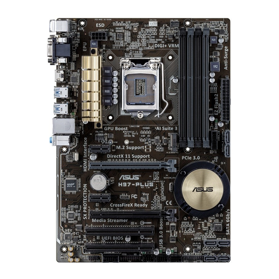
1.2.2 Screw holes Place six screws into the holes indicated by circles to secure the motherboard to the chassis. Place this side towards the rear of the chassis H97-PLUS Chapter 1: Product introduction... - Page 13 CPU_FAN CHA_FAN2 DIGI +VRM EATX12V HDMI USB3_34 USB3_56 LAN_USB78 CHA_FAN1 AUDIO PCIEX1_1 8111GR PCIEX16_1 H97-PLUS BATTERY Intel ® 1083 PCIEX1_2 PCIEX16_2 Super 64Mb BIOS PCI1 SB_PWR PCI2 CLRTC SATA6G_6 SATA6G_5 SATA6G_4 SATA6G_3 SPDIF_OUT USB910 USB1112 USB1314 PANEL AAFP ASUS H97-PLUS...
-
Page 14: Central Processing Unit (Cpu)
1.2.4 Layout contents Connectors/Jumpers/Slots/LED Page 1-15 ® 1-21 1-21 1-12 1-15 Central Processing Unit (CPU) ® ® ® Pentium processors. H97-PLUS H97-PLUS CPU socket LGA1150 Chapter 1: Product introduction... - Page 15 1.3.1 Installing the CPU ASUS H97-PLUS...
- Page 16 1.3.2 CPU heatsink and fan assembly installation before you install the heatsink and fan if necessary. Chapter 1: Product introduction...
- Page 17 To install the CPU heatsink and fan assembly To uninstall the CPU heatsink and fan assembly ASUS H97-PLUS...
- Page 18 System memory 1.4.1 Overview Channel Sockets H97-PLUS H97-PLUS 240-pin DDR3 DIMM sockets 1.4.2 Memory configurations sockets. operation. ® ® ® motherboard. ® support site at Chapter 1: Product introduction...
-
Page 19: 2.5 Ai Tweaker Menu
2.5 Ai Tweaker menu ® www.asus.com 1.4.3 Installing a DIMM To install a DIMM ASUS H97-PLUS... - Page 20 To remove a DIMM Expansion slots the slots and the expansion cards that they support. cause you physical injury and damage motherboard components. 1.5.1 Installing an expansion card To install an expansion card: make the necessary hardware settings for the card. use.
- Page 21 – shared – – – – – – – – – shared – – – – shared – – – – – – – shared – – – – – – – – – shared – – ASUS H97-PLUS 1-11...
- Page 22 Clear RTC RAM (3-pin CLRTC) CLRTC H97-PLUS Normal Clear RTC (Default) H97-PLUS Clear RTC RAM To erase the RTC RAM: Turn OFF the computer and unplug the power cord. Plug the power cord and turn ON the computer. enter data. battery.