Table of Contents
Advertisement
Advertisement
Table of Contents

Related Manuals for Asus H97M-PLUS


Summary of Contents for Asus H97M-PLUS
- Page 1 H97M-PLUS...
- Page 2 Product warranty or service will not be extended if: (1) the product is repaired, modified or altered, unless such repair, modification of alteration is authorized in writing by ASUS; or (2) the serial number of the product is defaced or missing.
-
Page 3: Table Of Contents
Contents Safety information ..................iv About this guide ..................iv Package contents ..................vi H97M-PLUS specifications summary ............vi Product introduction ............. 1-1 Before you proceed ..............1-1 Motherboard overview ..............1-1 Central Processing Unit (CPU) ........... 1-3 System memory ................1-6 Expansion slots ................ -
Page 4: Safety Information
Safety information Electrical safety • To prevent electrical shock hazard, disconnect the power cable from the electrical outlet before relocating the system. • When adding or removing devices to or from the system, ensure that the power cables for the devices are unplugged before the signal cables are connected. If possible, disconnect all power cables from the existing system before you add a device. -
Page 5: Conventions Used In This Guide
Refer to the following sources for additional information and for product and software updates. ASUS websites The ASUS website provides updated information on ASUS hardware and software products. Refer to the ASUS contact information. Optional documentation Your product package may include optional documentation, such as warranty flyers, that may have been added by your dealer. -
Page 6: Package Contents
* Hyper DIMM support is subject to the physical characteristics of individual CPUs. Please refer to Memory QVL (Qualified Vendors List) for details. ** Refer to www.asus.com for the Memory QVL (Qualified Vendors List). 1 x PCI Express 3.0/2.0 x16 slot (at x16 mode) Expansion slots 1 x PCI Express 2.0 x16 slot (max. - Page 7 ASUS 5X Protection features - ASUS motherboards safeguard your PC with 5X PROTECTION: DIGI+ VRM, DRAM Fuse, ESD Guards, High-Quality 5K-Hour Solid Capacitors, and Stainless Steel Back I/O ensure the best quality, reliability, and durability ASUS Digital Power Design...
- Page 8 - Monitor your PC status with smart devices in real time UEFI BIOS EZ Mode - featuring friendly graphics user interface - ASUS O.C. Tuner - ASUS CrashFree BIOS 3 - ASUS EZ Flash 2 ASUS Q-Design - ASUS Q-Slot...
- Page 9 64 Mb Flash ROM, UEFI AMI BIOS, PnP, DMI 2.7, WfM 2.0, SM BIOS BIOS features 2.8, ACPI 5.0, Multi-language BIOS, ASUS EZ Flash 2, CrashFree BIOS 3, F11 EZ Tuning Wizard, F6 Qfan Control, F3 My Favorites, Quick Note,...
-
Page 11: Product Introduction
Placement direction When installing the motherboard, place it into the chassis in the correct orientation. The edge with external ports goes to the rear part of the chassis as indicated in the image. 1.2.2 Screw holes Place six screws into the holes indicated by circles to secure the motherboard to the chassis. Do not overtighten the screws! Doing so can damage the motherboard. ASUS H97M-PLUS... -
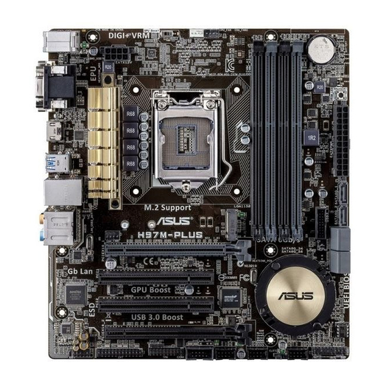
Page 12: Motherboard Layout
Place this side towards the rear of the chassis H97M-PLUS 1.2.3 Motherboard layout 22.4cm(8.8in) CHA_FAN2 KBMS CPU_FAN GPU_LED BATTERY DIGI +VRM EATX12V MemOK! DRAM_LED HDMI 1442K LGA1150 USB3_56 LAN_USB3_34 AUDIO CHA_FAN1 H97M-PLUS PCIEX16_1 Intel I218V PCI1 Intel ® Super 1083... -
Page 13: Central Processing Unit (Cpu)
14. System panel connector (20-8 pin F_PANEL) 1-19 15. USB 2.0 connectors (10-1 pin USB910, USB1112, USB1314) 1-17 16. Serial port connector (10-1 pin COM) 1-13 17. TPM connector (20-1 pin TPM) 1-17 18. Digital audio connector (4-1 pin SPDIF_OUT) 1-16 19. LPT connector (26-1 pin LPT) 1-18 20. Front panel audio connector (10-1 pin AAFP) 1-15 Central Processing Unit (CPU) The motherboard comes with a surface mount LGA1150 socket designed for the 4th, New 4th & 5th Generation Intel Core™ i7 / i5 / i3, Pentium and Celeron processors. ® ® ® H97M-PLUS H97M-PLUS CPU socket LGA1150 ASUS H97M-PLUS... -
Page 14: Installing The Cpu
Unplug all power cables before installing the CPU. • Upon purchase of the motherboard, ensure that the PnP cap is on the socket and the socket contacts are not bent. Contact your retailer immediately if the PnP cap is missing, or if you see any damage to the PnP cap/socket contacts/motherboard components. ASUS will shoulder the cost of repair only if the damage is shipment/ transit-related. • Ensure that you install the correct CPU designed for LGA1150 only. DO NOT install a CPU designed for LGA1155 and LGA1156 sockets on the LGA1150 socket. • Keep the cap after installing the motherboard. ASUS will process Return Merchandise Authorization (RMA) requests only if the motherboard comes with the cap on the LGA1150 socket. • The product warranty does not cover damage to the socket contacts resulting from incorrect CPU installation/removal, or misplacement/loss/incorrect removal of the PnP cap. 1.3.1 Installing the CPU Chapter 1: Product introduction... -
Page 15: Cpu Heatsink And Fan Assembly Installation
1.3.2 CPU heatsink and fan assembly installation Apply the Thermal Interface Material to the CPU heatsink and CPU before you install the heatsink and fan if necessary. To install the CPU heatsink and fan assembly ASUS H97M-PLUS... -
Page 16: System Memory
To uninstall the CPU heatsink and fan assembly System memory 1.4.1 Overview This motherboard comes with four Double Data Rate 3 (DDR3) Dual Inline Memory Module (DIMM) sockets. The figure illustrates the location of the DDR3 DIMM sockets: Channel Sockets Channel A DIMM_A1 and DIMM_A2 H97M-PLUS Channel B DIMM_B1 and DIMM_B2 H97M-PLUS 240-pin DDR3 DIMM sockets Chapter 1: Product introduction... -
Page 17: Memory Configurations
Use a maximum of 3GB system memory if you are using a 32-bit Windows OS. ® I nstall a 64-bit Windows OS if you want to install 4GB or more on the ® motherboard. F or more details, refer to the Microsoft® support site at http://support.microsoft. com/kb/929605/en-us. • This motherboard does not support DIMMs made up of 512 megabits (Mb) chips or less. • The default memory operation frequency is dependent on its Serial Presence Detect (SPD), which is the standard way of accessing information from a memory module. Under the default state, some memory modules for overclocking may operate at a lower frequency than the vendor-marked value. To operate at the vendor-marked or at a higher frequency, refer to section 2.5 Ai Tweaker menu for manual memory frequency adjustment. • For system stability, use a more efficient memory cooling system to support a full memory load (4 DIMMs) or overclocking condition. • Visit the ASUS website at: www.asus.com for the latest QVL. • ASUS exclusively provides hyper DIMM support function. • Hyper DIMM support is subject to the physical characteristics of individual CPUs. Load the X.M.P. or D.O.C.P. settings in the BIOS for the hyper DIMM support. ASUS H97M-PLUS... -
Page 18: Installing A Dimm
1.4.3 Installing a DIMM To install a DIMM To remove a DIMM Chapter 1: Product introduction... -
Page 19: Expansion Slots
Remove the system unit cover (if your motherboard is already installed in a chassis). Remove the bracket opposite the slot that you intend to use. Keep the screw for later use. Align the card connector with the slot and press firmly until the card is completely seated on the slot. Secure the card to the chassis with the screw you removed earlier. Replace the system cover. 1.5.2 Configuring an expansion card After installing the expansion card, configure it by adjusting the software settings. Turn on the system and change the necessary BIOS settings, if any. See Chapter 2 for information on BIOS setup. Assign an IRQ to the card. Install the software drivers for the expansion card. When using PCI cards on shared slots, ensure that the drivers support “Share IRQ” or that the cards do not need IRQ assignments. Otherwise, conflicts will arise between the two PCI groups, making the system unstable and the card inoperable. 1.5.3 PCI slot The PCI slots support cards such as a LAN card, SCSI card, USB card, and other cards that comply with PCI specifications. 1.5.4 PCI Express 3.0/2.0 x16 slot This motherboard has a PCI Express 3.0/2.0 x16 slot that supports PCI Express 3.0/2.0 x16 graphic cards complying with the PCI Express specifications. ASUS H97M-PLUS... -
Page 20: Jumpers
– Jumpers Clear RTC RAM (3-pin CLRTC) This jumper allows you to clear the Real Time Clock (RTC) RAM in CMOS. You can clear the CMOS memory of date, time, and system setup parameters by erasing the CMOS RTC RAM data. The onboard button cell battery powers the RAM data in CMOS, which include system setup information such as system passwords. CLRTC H97M-PLUS Normal Clear RTC (Default) H97M-PLUS Clear RTC RAM To erase the RTC RAM: Turn OFF the computer and unplug the power cord. Move the jumper cap from pins 1-2 (default) to pins 2-3. Keep the cap on pins 2-3 for about 5-10 seconds, then move the cap back to pins 1-2. Plug the power cord and turn ON the computer. Hold down the <Del> key during the boot process and enter BIOS setup to re- enter data. Except when clearing the RTC RAM, never remove the cap on CLRTC jumper default position. Removing the cap will cause system boot failure! 1-10 Chapter 1: Product introduction... -
Page 21: Connectors
10Mbps connection LAN port Orange Linked ORANGE 100Mbps connection Orange (Blinking) Data activity GREEN 1Gbps connection Orange (Blinking Ready to wake then steady) up from S5 mode Center / Subwoofer port (orange). This port connects the center/subwoofer speakers. Rear Speaker Out port (black). This port connects the rear speakers in a 4.1-channel, 5.1-channel, or 7.1-channel audio configuration. ASUS H97M-PLUS 1-11... - Page 22 Line In port (light blue). This port connects the tape, CD, DVD player, or other audio sources. Line Out port (lime). This port connects a headphone or a speaker. In 4.1-channel, 5.1-channel, and 7.1-channel configurations, the function of this port becomes Front Speaker Out. Microphone port (pink). This port connects a microphone. Side Speaker Out port (gray). This port connects the side speaker in an 7.1-channel audio configuration. Refer to the audio configuration table below for the function of the audio ports in 2.1, 4.1, 5.1, or 7.1-channel configuration. Audio 2.1, 4.1, 5.1, or 7.1-channel configuration Headset Port 4.1-channel...
-
Page 23: Internal Connectors
Serial port connector (10-1 pin COM) This connector is for a serial (COM) port. Connect the serial port module cable to this connector, then install the module to a slot opening at the back of the system chassis. PIN 1 H97M-PLUS H97M-PLUS Serial port (COM) connector The COM module is purchased separately. CPU and chassis fan connectors (4-pin CPU_FAN, and 4-pin CHA_FAN1/2) Connect the fan cables to the fan connectors on the motherboard, ensuring that the black wire of each cable matches the ground pin of the connector. - Page 24 H97 Serial ATA 6.0Gb/s connectors (7-pin SATA6G_1~6) ® These connectors connect to Serial ATA 6.0 Gb/s hard disk drives via Serial ATA 6.0 Gb/s signal cables. If you installed Serial ATA hard disk drives, you can create a RAID 0, 1, 5, and 10 configuration with the Intel Rapid Storage Technology through the onboard Intel H97 ® ® chipset. H97M-PLUS H97M-PLUS SATA 6.0Gb/s connectors • These connectors are set to [AHCI] by default. If you intend to create a Serial ATA RAID set using these connectors, set the SATA Mode Selection item in the BIOS to [RAID]. See section 2.6.3 PCH Storage Configuration for details. • Before creating a RAID set, refer to the RAID Supplementary Guide included in the folder named Manual in the support DVD. • When using hot-plug and NCQ, set the SATA Mode Selection item in the BIOS to [AHCI]. •...
- Page 25 Front panel audio connector (10-1 pin AAFP) This connector is for a chassis-mounted front panel HD audio I/O module. Connect one end of the front panel audio I/O module cable to this connector. AAFP PIN 1 H97M-PLUS HD-audio-compliant Legacy AC’97 pin definition compliant definition H97M-PLUS Front panel audio connector • We recommend that you connect a high-definition front panel audio module to this connector to avail of the motherboard’s high-definition audio capability. • If you want to connect a high-definition or an AC’97 front panel audio module to this connector, set the Front Panel Type item in the BIOS setup to [HD] or [AC97]. USB 3.0 connector (20-1 pin USB3_12) This connector allows you to connect a USB 3.0 module for additional USB 3.0 front or rear panel ports. With an installed USB 3.0 module, you can enjoy all the benefits of USB 3.0 including faster data transfer speeds up to 5Gbps, faster charging time for USB-chargeable devices, optimized power efficiency, and backward compatibility with USB 2.0.
- Page 26 Power OK -5 Volts +5 Volts PIN 1 PSON# +5 Volts H97M-PLUS +3 Volts -12 Volts +3 Volts +3 Volts PIN 1 H97M-PLUS ATX power connectors • For a fully configured system, we recommend that you use a power supply unit (PSU) that complies with ATX 12 V Specification 2.3 (or later version) and provides a minimum power of 350 W. • DO NOT forget to connect the 4-pin/8-pin EATX12 V power plug. Otherwise, the system will not boot. • We recommend that you use a PSU with a higher power output when configuring a system with more power-consuming devices. The system may become unstable or may not boot up if the power is inadequate.
- Page 27 USB 2.0 connectors (10-1 pin USB910, USB1112, USB1314) These connectors are for USB 2.0 ports. Connect the USB module cable to any of these connectors, then install the module to a slot opening at the back of the system chassis. These USB connectors comply with USB 2.0 specification that supports up to 480 Mbps connection speed. USB910 USB1112 USB1314 H97M-PLUS PIN 1 PIN 1 PIN 1 H97M-PLUS USB2.0 connectors Never connect a 1394 cable to the USB connectors. Doing so will damage the motherboard! The USB 2.0 module is purchased separately. TPM connector (20-1 pin TPM) This connector supports a Trusted Platform Module (TPM) system, which can securely store keys, digital certificates, passwords, and data. A TPM system also helps enhance network security, protects digital identities, and ensures platform integrity. PIN 1 H97M-PLUS H97M-PLUS TPM Connector The TPM module is purchased separately.
- Page 28 LPT connector (26-1 pin LPT) The LPT (Line Printing Terminal) connector supports devices such as a printer. LPT standardizes as IEEE 1284, which is the parallel port interface on IBM PC-compatible computers. PIN 1 H97M-PLUS H97M-PLUS Parallel Port Connector SATA M.2 connector This connector is for a SATA M.2-compliant solid-state drive (SSD). The M.2 standard supports data transfer speeds up to 10.0Gb/s. M.2(SOCKET3) H97M-PLUS H97M-PLUS M.2(SOCKET3) • This socket supports M Key and type 2260/2280 storage devices. • The M.2 Socket 3 shares bandwidth with SATA ports 5 and 6. Refer to section 2.6.3 PCH Storage Configuration of this user guide for more details. • When using Intel Desktop Responsiveness technologies with PCIe M.2 device,...
-
Page 29: System Panel Connector 20-8 Pin Panel
System panel connector (20-8 pin PANEL) This connector supports several chassis-mounted functions. PWR_LED SPEAKER PANEL PIN 1 H97M-PLUS HDD_LED PWR_SW RESET H97M-PLUS System panel connector • System power LED (2-pin PWR_LED) This 2-pin connector is for the system power LED. Connect the chassis power LED cable to this connector. The system power LED lights up when you turn on the system power, and blinks when the system is in sleep mode. • Hard disk drive activity LED (2-pin HDD_LED) This 2-pin connector is for the HDD Activity LED. Connect the HDD Activity LED cable to this connector. The HDD LED lights up or flashes when data is read from or written to the HDD. • System warning speaker (4-pin SPEAKER) This 4-pin connector is for the chassis-mounted system warning speaker. The speaker allows you to hear system beeps and warnings. -
Page 30: Onboard Switches
Onboard switches Onboard switches allow you to fine-tune performance when working on a bare or open-case system. This is ideal for overclockers and gamers who continually change settings to enhance system performance. MemOK! switch Installing DIMMs that are incompatible with the motherboard may cause system boot failure, and the DRAM_LED near the MemOK! switch lights continuously. Press and hold the MemOK! switch until the DRAM_LED starts blinking to begin automatic memory compatibility tuning for successful boot. H97M-PLUS H97M-PLUS MemOK! button • Refer to section 1.9 Onboard LEDs for the exact location of the DRAM_LED. • The DRAM_LED also lights when the DIMM is not properly installed. Turn off the system and reinstall the DIMM before using the MemOK! function. • The MemOK! switch does not function under Windows® OS environment. • During the tuning process, the system loads and tests failsafe memory settings. It takes about 30 seconds for the system to test one set of failsafe settings. If the test fails, the system reboots and test the next set of failsafe settings. The blinking speed of the DRAM_LED increases, indicating different test processes. • Due to memory tuning requirement, the system automatically reboots when each timing set is tested. If the installed DIMMs still fail to boot after the whole tuning process, the DRAM_LED lights continuously. Replace the DIMMs with ones recommended in the Memory QVL (Qualified Vendors Lists) on the ASUS website at www.asus.com. - Page 31 GPU Boost switch This switch allows you to enable or disable the GPU Boost function. Disable Enable (Default) H97M-PLUS H97M-PLUS GPU switch ASUS H97M-PLUS 1-21...
-
Page 32: Onboard Leds
Onboard LEDs Standby Power LED The motherboard comes with a standby power LED that lights up to indicate that the system is ON, in sleep mode, or in soft-off mode. This is a reminder that you should shut down the system and unplug the power cable before removing or plugging in any motherboard component. The illustration below shows the location of the onboard LED. H97M-PLUS SB_PWR H97M-PLUS Onboard LED DRAM LED DRAM LED checks the DRAM in sequence during motherboard booting process. If an error is found , the LED next to the error device will continue lighting until the problem is solved. This user-friendly design provides an intuitional way to locate the root problem within a second. MemOK! LED H97M-PLUS H97M-PLUS MemOK! LED GPU Boost LED The GPU Boost LED lights up when the GPU Boost switch is enabled. GPU_LED H97M-PLUS H97M-PLUS GPU LED 1-22 Chapter 1: Product introduction... -
Page 33: Software Support
Support DVD information The Support DVD that comes with the motherboard package contains the drivers, software applications, and utilities that you can install to avail all motherboard features. The contents of the Support DVD are subject to change at any time without notice. Visit the ASUS website at www.asus.com for updates. To run the Support DVD Place the Support DVD into the optical drive. If Autorun is enabled in your computer, the DVD automatically displays the Specials screen which lists the unique features of your ASUS motherboard. Click Drivers, Utilities, AHCI/RAID Driver, Manual, Contact, and Specials tabs to display their respective menus. The following screen is for reference only. Click an icon to display Support DVD/motherboard information Click an item to install If Autorun is NOT enabled in your computer, browse the contents of the Support DVD to locate the file ASSETUP.EXE from the BIN folder. Double-click the ASSETUP.EXE to run the DVD. ASUS H97M-PLUS 1-23... - Page 34 1-24 Chapter 1: Product introduction...
-
Page 35: Bios Information
Managing and updating your BIOS Save a copy of the original motherboard BIOS file to a USB flash disk in case you need to restore the BIOS in the future. Copy the original motherboard BIOS using the ASUS Update utility. -
Page 36: Asus Ez Flash
2.1.3 ASUS CrashFree BIOS 3 utility The ASUS CrashFree BIOS 3 is an auto recovery tool that allows you to restore the BIOS file when it fails or gets corrupted during the updating process. You can restore a corrupted BIOS file using the motherboard support DVD or a USB flash drive that contains the updated BIOS file. -
Page 37: Recovering The Bios
The utility automatically checks the devices for the BIOS file. When found, the utility reads the BIOS file and enters ASUS EZ Flash 2 utility automatically. The system requires you to enter BIOS Setup to recover BIOS settings. To ensure system compatibility and stability, we recommend that you press <F5>... - Page 38 ENTER to select boot device ESC to boot using defaults P2: ST3808110AS (76319MB) aigo miniking (250MB) UEFI: (FAT) ASUS DRW-2014L1T(4458MB) P1: ASUS DRW-2014L1T(4458MB) UEFI: (FAT) aigo miniking (250MB) Enter Setup When the booting message appears, press <Enter> within five (5) seconds to enter FreeDOS prompt.
- Page 39 DO NOT shut down or reset the system while updating the BIOS to prevent system boot failure. Ensure to load the BIOS default settings to ensure system compatibility and stability. Select the Load Optimized Defaults item under the Exit BIOS menu. See Chapter 2 of your motherboard user guide for details. ASUS H97M-PLUS...
-
Page 40: Bios Setup Program
The BIOS setup screens shown in this section are for reference purposes only, and may not exactly match what you see on your screen. • Visit the ASUS website at www.asus.com to download the latest BIOS file for this motherboard. •... -
Page 41: Advanced Mode
The Advanced Mode provides advanced options for experienced end‑users to configure the BIOS settings. The figure below shows an example of the Advanced Mode. Refer to the following sections for the detailed configurations. To access the EZ Mode, press F7. ASUS H97M-PLUS 2‑7... -
Page 42: Menu Bar
Quick settings bar Configuration fields Hardware information Menu bar General help Menu items Last modified Enters EZ mode settings Submenu item Drop-down list Scroll bar Quick settings bar The quick settings bar on top of the screen has the following main items: For setting the system date and time For setting the system language For saving the frequently‑used system settings and configuration... -
Page 43: Menu Items
This button above the menu bar allows you to key in notes of the activities that you have done in BIOS. • The Quick Note function does not support the following keyboard functions: delete, cut, copy and paste. • You can only use the alphanumeric characters to enter your notes. Hot keys ASUS H97M-PLUS... -
Page 44: My Favorites
This button above the menu bar contains the navigation keys for the BIOS setup program. Use the navigation keys to select items in the menu and change the settings. Last Modified button This button shows the items that you last modified and save in BIOS Setup. Hardware Monitor At the right side of the menu screen is a brief description of system hardware monitor information. -
Page 45: Main Menu
RAM to clear the BIOS password. See section 1.6 Jumpers for information on how to erase the RTC RAM. • The Administrator or User Password items on top of the screen show the default Not Installed. After you set a password, these items show Installed. ASUS H97M-PLUS 2-11... -
Page 46: Administrator Password
Administrator Password If you have set an administrator password, we recommend that you enter the administrator password for accessing the system. Otherwise, you might be able to see or change only selected fields in the BIOS setup program. To set an administrator password: Select the Administrator Password item and press <Enter>. -
Page 47: Ai Tweaker Menu
Be cautious when changing the settings of the Ai Tweaker menu items. Incorrect field values can cause the system to malfunction. The configuration options for this section vary depending on the CPU and DIMM model you installed on the motherboard. Scroll down to display the following items: ASUS H97M-PLUS 2‑13... - Page 48 Target CPU Turbo-Mode Frequency: xxxxMHz Displays the target CPU Turbo‑Mode frequency. Target DRAM Frequency: xxxxMHz Displays the target DRAM frequency. Target Cache Frequency: xxxxMHz Displays the target Cache frequency. Target DMI/PEG Frequency: xxxxMHz Displays the target DMI/PEG frequency. Target CPU Graphics Frequency: xxxxMHz Displays the target iGPU frequency.
-
Page 49: Dram Timing Control
2.5.9 EPU Power Saving Mode [Disabled] ASUS EPU (Energy Processing Unit) sets the CPU in its minimum power consumption settings. Enable this item to set lower CPU VCCIN and Vcore voltages and achieve the best energy saving condition. Configuration options: [Disabled] [Enabled] 2.5.10... - Page 50 2.5.11 DIGI+ VRM CPU Load-Line Calibration [Auto] Load‑line is defined by Intel VRM specification and affects the CPU power voltage. The CPU working voltage will decrease proportionally depending on the CPU loading. Higher levels of the load‑line calibration can get a higher voltage and a better overclocking performance but increases the CPU and VRM thermal.
- Page 51 When enabled, it allows CPU to take precautionary actions when the thermal of the external regulator exceeds the limit. Configuration options: [Auto] [Disabled] [Enabled] CPU Integrated VR Fault Management [Auto] Allows you to manage the CPU Integrated VR fault. Configuration options: [Auto] [Disabled] [Enabled] ASUS H97M-PLUS 2‑17...
- Page 52 CPU Internal Power Configuration CPU Integrated VR Efficiency Management [Auto] Allows you to manage the CPU integrated VR efficiency. Configuration options: [Auto] [High Performance] [Balanced] Power Decay Mode [Auto] Enable to improve power saving on the Fully Integrated Voltage Regulator as the processor enters low current mode.
- Page 53 CPU Graphics Voltage Override [Auto] This item appears only when you set the CPU Graphics Voltage to [Manual Mode] and allows you to set the CPU graphics voltage override. The values range from 0.001V to 1.920V with a 0.001V interval. ASUS H97M-PLUS 2-19...
- Page 54 Offset Mode Sign [+] This item appears only when you set the CPU Graphics Voltage to [Offset Mode] or [Adaptive Mode] and allows you to set the offset mode sign. Configuration options: [+] [‑] CPU Graphics Voltage Offset [Auto] This item appears only when you set the CPU Graphics Voltage to [Offset Mode] or [Adaptive Mode] and allows you to set the CPU graphics voltage offset.
- Page 55 Allows you to set the DRAM DATA REF Voltage on CHA/CHB. The values range from 0.39500V to 0.63000V with a 0.00500V interval. 2.5.27 CPU Spread Spectrum [Auto] [Auto] Automatic configuration. [Disabled] Enhances the BCLK overclocking ability. [Enabled] Sets to [Enabled] for EMI control. ASUS H97M-PLUS 2-21...
-
Page 56: Advanced Menu
Advanced menu The Advanced menu items allow you to change the settings for the CPU and other system devices. Be cautious when changing the settings of the Advanced menu items. Incorrect field values can cause the system to malfunction. 2.6.1 CPU Configuration The items in this menu show the CPU‑related information that the BIOS automatically detects. - Page 57 The operating system controls the CPU speed. Turbo Mode [Enabled] Allows you to set the processor cores to run faster than the marked frequency in a specific condition. Configuration options: [Enabled] [Disabled] Turbo Mode is only available on selected CPU models only. ASUS H97M-PLUS 2‑23...
-
Page 58: Pch Configuration
CPU C states [Auto] [Auto] Automatic configuration. [Enabled] Enables the CPU C states. [Disabled] Disables the CPU C states.. The following items appear only when you set the CPU C states to [Enabled]. Enhanced C1 state [Enabled] [Enabled] Enables enhanced C1 state. [Disabled] Disables enhanced C1 state. -
Page 59: Intel Smart Connect Technology
Set to [AHCI] when you want the SATA hard disk drives to use the AHCI (Advanced Host Controller Interface). The AHCI allows the onboard storage driver to enable advanced Serial ATA features that increases storage performance on random workloads by allowing the drive to internally optimize the order of commands. ASUS H97M-PLUS 2-25... -
Page 60: System Agent Configuration
[RAID] Set to [RAID Mode] when you want to create a RAID configuration from the SATA hard disk drives. Aggressive LPM Support [Disabled] This item appears only when you set SATA Mode Selection to [AHCI] and allows you to enable or disable PCH entering link power state aggressively. Configuration options: [Disabled] [Enabled] S.M.A.R.T. -
Page 61: Dmi Configuration
Keeps the last operation of xHCI controller in OS during bootup. [Smart Auto] Enables the operation of xHCI controller. [Enabled] Enables the function. [Disabled] Disables the function. EHCI Hand-off [Disabled] [Enabled] Enables the support for operating systems without an EHCI hand‑off feature. [Disabled] Disables the function. ASUS H97M-PLUS 2‑27... -
Page 62: Platform Misc Configuration
USB Single Port Control USB3_1~6 [Enabled] Allows you to enable or disable an individual USB port. Refer to the section 1.2.3 Motherboard layout in this user manual for the locations of the USB ports. Configuration options: [Enabled] [Disabled]. USB 7~14 [Enabled] Allows you to enable or disable an individual USB port. -
Page 63: Serial Port Configuration
IRQ=3] [IO=3E8h; IRQ=4] [IO=2E8h; IRQ=3] Parallel Port Configuration The sub‑items in this menu allow you to set the parallel port configuration. Parallel Port [On] Allows you to enable or disable the parallel port (LPT). Configuration options: [On] [Off] ASUS H97M-PLUS 2-29... - Page 64 Change Settings [Auto] Allows you to select an optimal setting for Super I/O devices. Configuration options: [Auto] [IO=378h; IRQ=5;] [IO=378h; IRQ=5,6,7,9,10,11,12;] [IO=278h; IRQ=5,6,7,9,10,11,12;] [IO=3BCh; IRQ=5,6,7,9,10,11,12;] Device Mode [STD Printer Mode] Allows you to change the printer port mode. Configuration options: [STD Printer Mode] [SPP Mode] [EPP‑1.9 and SPP Mode] [EPP‑1.7 and SPP Mode] [ECP Mode] [ECP and EPP 1.9 Mode] [ECP and EPP 1.7 Mode] 2.6.8...
-
Page 65: Monitor Menu
This item allows user to disable or enable the Ipv4 / Ipv6 PXE Boot support. Configuration options: [Disabled] [Enabled] Monitor menu The Monitor menu displays the system temperature/power status, and allows you to change the fan settings. ASUS H97M-PLUS 2‑31... - Page 66 Scroll down to display the following items: 2.7.1 QFan Tuning Click this item to automatically detect the lowest speed and configure the minimum duty cycle for each fan. 2.7.2 CPU / MB Temperature [xxxºC/xxxºF] The onboard hardware monitor automatically detects and displays the CPU / motherboard temperature.
- Page 67 Use the <+> and <‑> keys to adjust the minimum CPU fan duty cycle. The values range from 20% to 100%. When the CPU temperature is under the lower limit, the CPU fan will operate at the minimum duty cycle. ASUS H97M-PLUS 2‑33...
- Page 68 2.7.6 Chassis Fan 1/2 Q-Fan Control [DC Mode] [Disabled] Disables the Chassis Q‑Fan control feature. [PWM Mode] Enables DC mode Q‑Fan control for a 4‑pin chassis fan. [DC Mode] Enables the Chassis Q‑Fan control feature for a 3‑pin chassis fan. Chassis Fan 1/2 Q-Fan Source [CPU] The assigned fan will be controlled according to the selected temperature source.
-
Page 69: Boot Menu
This item allows you to enable or disable the Anti Surge function. Configuration options: [Disabled] [Enabled] Boot menu The Boot menu items allow you to change the system boot options. Scroll down to display the following items: ASUS H97M-PLUS 2‑35... - Page 70 2.8.1 Fast Boot [Enabled] [Enabled] Select to accelerate the boot speed. [Disabled] Select to go back to normal boot. The following five items appear when you set Fast Boot to [Enabled]. SATA Support [All Devices] [All Devices] All devices connected to SATA ports will be available during POST.
- Page 71 Option ROM Messages [Enabled] [Enabled] The option ROM messages will be shown during the POST (Power‑on self‑ test). [Disabled] Only the ASUS logo will be shown during POST. 2.8.6 Interrupt 19 Capture [Disabled] [Enabled] Allows the option ROMs to trap Interrupt 19.
-
Page 72: Secure Boot
2.8.9 CSM (Compatibility Support Module) Allows you to configure the CSM (Compatibility Support Module) items to fully support the various VGA, bootable devices and add‑on devices for better compatibility. Launch CSM [Enabled] [Auto] The system automatically detects the bootable devices and the add‑on devices. - Page 73 No to append a downloaded additional KEK from a USB storage device for the db (signature database) and dbx (revoked signature database) management. The KEK file must be formatted as a UEFI variable structure with time‑based authenticated variable. ASUS H97M-PLUS 2‑39...
-
Page 74: Boot Option Priorities
• To select the boot device during system startup, press <F8> when ASUS Logo appears. • To access Windows OS in Safe Mode, do any of the following: •... -
Page 75: Tools Menu
<Enter> to display the submenu. 2.9.1 ASUS EZ Flash 2 Utility Allows you to run ASUS EZ Flash 2. Press [Enter] to launch the ASUS EZ Flash 2 screen. For more details, see section 2.1.2 ASUS EZ Flash 2. 2.9.2 Setup Animator [Enabled] Enables or disables Setup Animator. -
Page 76: Exit Menu
2.10 Exit menu The Exit menu items allow you to load the optimal default values for the BIOS items, and save or discard your changes to the BIOS items. Load Optimized Defaults This option allows you to load the default values for each of the parameters on the Setup menus. -
Page 77: Appendices
Cet appareil est conforme aux normes CNR exemptes de licence d’Industrie Canada. Le fonctionnement est soumis aux deux conditions suivantes : (1) cet appareil ne doit pas provoquer d’interférences et (2) cet appareil doit accepter toute interférence, y compris celles susceptibles de provoquer un fonctionnement non souhaité de l’appareil. H97M-PLUS... -
Page 78: Canadian Department Of Communications Statement
ASUS Recycling/Takeback Services ASUS recycling and takeback programs come from our commitment to the highest standards for protecting our environment. We believe in providing solutions for you to be able to responsibly recycle our products, batteries, other components as well as the packaging materials. -
Page 79: Asus Contact Information
+1-510-739-3777 +1-510-608-4555 Web site http://www.asus.com/us/ Technical Support Support fax +1-812-284-0883 Telephone +1-812-282-2787 Online support http://www.service.asus.com/ ASUS COMPUTER GmbH (Germany and Austria) Address Harkort Str. 21-23, D-40880 Ratingen, Germany +49-2102-959911 Web site http://www.asus.com/de Online contact http://eu-rma.asus.com/sales Technical Support Telephone +49-1805-010923* Support Fax... - Page 80 Appendices...