
Related Manuals for Samsung MOS-C1


Summary of Contents for Samsung MOS-C1
- Page 1 Energy Recovery Ventilator Installation manual MOS-C1 / MOS-C1DZ Thank you for purchasing this Samsung Product. Before operating this unit, please read this installation manual carefully and retain it for future reference.
-
Page 2: Safety Information
SAFETY INFORMATION This information is provided to prevent personal injury and material damage. Please read all safety information before use WARNING CAUTION Risk of death or serious personal Potential risk of personal injury or injury. material damage. WARNING Please contact the Service Always use rated voltage. - Page 3 SAFETY INFORMATION (Continued) CAUTION Do not expose the product to Install the product in a place excessive heat or flammable without moisture. sources Moisture may cause damage to the product and electric shock. Potential risk of fire hazard or explosion. Use only rated parts for Electric wiring should be installation.
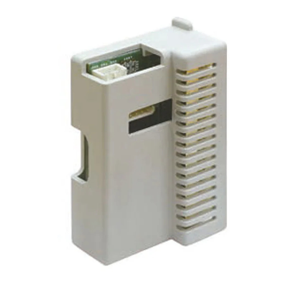
- Page 4 INSTALLATION OF CO SENSOR Parts Installation Parts CO Sensor Cable Bolt Cable Tie INSU manual Image Instructions Applicable Models: RHF025EE, AN026JSKLKN 1) Turn off the power and Back disconnect the product from power supply. Front 2) Unscrew the three bolts from the maintenance cover.
- Page 5 INSTALLATION OF CO SENSOR (Continued) 4) Disengage the connector attached to the damper for ventilation switch. Pull the body part outward to disengage the connector. 5) Unscrew the four bolts and B-Part disengage the B-Part of the bracket body element from the product.
- Page 6 INSTALLATION OF CO SENSOR (Continued) 9) Attach the INSU to a place where Sensor is to be positioned. INSU 10) Position the CO Sensor onto the hole and secure in place with a bolt. It is connected to the RA duct. Bolt Sensor 11) Secure the cable to the two...
- Page 7 INSTALLATION OF CO SENSOR (Continued) Instructions Applicable Models: RHF035EE/RHF050EE/RHF080EE/RHF100EE, AN035/050/080/100JSKLKN 1) Turn off the power and Back disconnect the product from power supply. It is not necessary to disassemble the product to replace or clean Front the fan, motor, heat exchange unit, or dust filter.
- Page 8 INSTALLATION OF CO SENSOR (Continued) 5) Unscrew the four bolts and remove the electric system cover. Bolt 6) Position the INSU in the hole located on the right side of the damper. INSU 7) Connect the white terminal of the cable to the CO Sensor.
- Page 9 INSTALLATION OF CO SENSOR (Continued) 9) Secure the cable to the two holders using cable ties. Cable Tie 10) Take out the CO Sensor cable together with other cables and reassemble the guide filter. Guide Filter 11) Take out the CO Sensor cable together with other cables through the outlet located on...
- Page 10 INSTALLATION OF PCB OPTION Configuration of CO Sensor 1) Applicable Models: RHF***** Switch off the K9 of SW06 in the MAIN PCB to set the CO Sensor to “Use” mode. Carbon dioxide (CO sensor connector K9 K10 K11 K12 2) Applicable Models: AN********* Carbon dioxide (CO sensor connector...
- Page 11 INSTALLATION OF PCB OPTION (Continued) Set SEG15 in Installation Option 5 for the product to "1". Changing a particular option Particular option can be set with a wireless remote controller only. You can change each digit of set option. Option SEG1 SEG2 SEG3...
- Page 12 INSTALLATION OF PCB OPTION (Continued) 2) Press the K4 switch (applicable models: RHF*****) or K2 switch (applicable models: AN*********) in the MAIN PCB 5 times in succession to check CO level is displayed properly. Applicable Models: RHF***** Applicable Models: AN********* c e d G2 b c e d c e d...
-
Page 13: Troubleshooting
중계기 설치 ◀ 계속 TROUBLESHOOTING LED1 does not flash when powered on Remove the cables from the main PCB and check PIN No.1-3 of CN43 for DC 12V. Is DC 12V generated? Replace the MAIN PCB. Connect the cables and check PIN No.1-3 of CON1 on the CO Sensor Connector for DC 12V. - Page 14 TROUBLESHOOTING (Continued) level is not displayed on the MAIN PCB “0” is displayed on the MAIN PCB. Check whether K9 in the MAIN PCB is switched off. Is K9 switched off? Or, are the options set? Switch off K9, and then check again. Or, set the options.
- Page 15 MEMO...