
Related Manuals for Husqvarna CEORA Razor 43M


Summary of Contents for Husqvarna CEORA Razor 43M
- Page 1 Operator's manual ™ HUSQVARNA CEORA Read the operator's manual carefully and make sure that you EN, English understand the instructions before you use the product.
-
Page 2: Table Of Contents
Contents 4.9 To stop the product..........27 1 Introduction 4.10 To set the product to OFF......... 27 1.1 Support..............3 4.11 To charge the battery........27 1.2 Product description..........3 4.12 To release the wheel brakes and move 1.3 System description..........3 the product.............. -
Page 3: Introduction
1.1 Support lawn mower and reference station uses the EPOS (Exact Positioning Operating System) technology with For support about the product, speak to your Husqvarna satellite signals to position the robotic lawn mower servicing dealer. correctly, this means that boundary wires are not necessary. -
Page 4: System Overview
1.4 System overview Satellites Work area Satellite signals Mobile device Reference station 10. Docking point Correction data 11. Transport path Charging station 12. Robotic lawn mower Virtual boundary 13. Maintenance point Stay-out zone Not included. Not included. 4 - Introduction 1691 - 002 - 14.01.2022... -
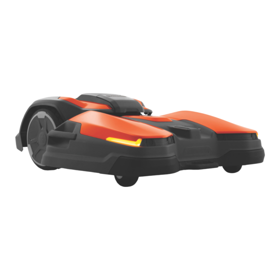
Page 5: Product Overview Drive Unit, Ceora
™ 1.5 Product overview drive unit, CEORA 544/546 EPOS Drive unit (DU) Drive wheels Rating plate drive unit Rear bumper Hatch Rear handles Drive unit body 10. Rear safety lights USB outlet for service tool 11. Active wheel brush kit Control panel ™... -
Page 6: Product Overview Charging Station, Ceora ™ Cs4
Cutting deck (CD) 10. Center top cover Lever 11. Side handles Shaft 12. Front handle Rating plate of the cutting deck 13. Front wheels Combi tool 14. Blade disc, blades, skid plate Cutting deck body 15. Service wheels Front safety lights 16. -
Page 7: Control Panel Overview
1.8 Control panel overview ON/OFF button Play button START button Maintenance point button ® Bluetooth button STOP button LED indicator Park button 1.9 LED indicator on the product The LED indicator on the control panel of the product shows the current product status: LED indicator light Product status Constant green... -
Page 8: Symbols On The Product
The product sets to OFF. Firmware installation is in progress. Flashes white New firmware must be installed. There is more information on www.husqvarna.com. Speak to your local Husqvarna representative for more information. 1.10 Symbols on the product The chassis contains components which are sensitive to electrostatic discharge These symbols can be found on the product. -
Page 9: General Manual Instructions
The status is EPOS action is necessary. The product has an accurate position but it is necessary to operate the product, manually or automatically, to get an accurate direction. The status is EPOS searching. The product does not have an accurate position and is searching for the satellite signals and the correction data to get an accurate position. -
Page 10: Safety
• To prevent damage to the product and accidents to • If there is a risk of thunderstorm, Husqvarna vehicles and persons, do not install work areas and recommends that the mains cable to the charging transport paths across public pathways. -
Page 11: Safety Instructions For Installation
To set the product to OFF work area. Refer to OFF before you lift the product. on page 27 . Husqvarna recommends to set the product to operate when the work area has no activity. The product can cause injury to animals at •... - Page 12 To lift the product manually on page 12 Refer to appDrive on page 26 . 2.7.1 To lift the product manually WARNING: Two persons are necessary to lift the product. CAUTION: Do not lift the product when it is parked in the charging station. It can cause damage to the charging station and/or the product.
-
Page 13: Installation
3.4 To examine where to put the reference station Note: Refer to www.husqvarna.com for more Read and understand the instructions about where to information about installation. put the reference station. Refer to the Operator's manual for the reference station. - Page 14 • If the product must not operate in a part of the • Husqvarna recommends to install the charging docking area, put a protective wall that is minimum station on a hard surface, such as concrete or 15 cm / 6 in. in height. The docking area is a equivalent.
-
Page 15: To Examine Where To Install The Objects On The Map
>110° ° 5 ° 5 • Put the charging station in an area with good airflow. • Use a residual-current device (RCD) with a tripping current of maximum 30 mA when you connect the mains cable to the power outlet. CAUTION: Do not install the charging station where there are metal objects... -
Page 16: Installation Of The Product
• For slopes more than 20% in the work area, isolate Make a map with work areas, stay-out zones, the slope with a stay-out zone. transport paths and maintenance points. Refer to Installation of the map objects on page 20 . •... - Page 17 13. Install the center top cover on the cutting deck. Align the shaft with the hole in the frame. 14. Close the hatch. 3.7.4 To remove the cutting deck Set the drive unit to OFF. Refer to To set the product to OFF on page 27 .
- Page 18 Drill 14 holes in the ground with a 6 mm drill. Attach the charging station to the ground with the 14 supplied screws. Use a 10 mm socket wrench to attach the screws. Put the 2 top baseplates on top of the lower baseplate.
- Page 19 For more information about Husqvarna Fleet Services ™ refer to www.husqvarna.com. Install the reference station according to the instructions in the Operator's manual for the reference station. 3.7.8.1 To connect to the product with Husqvarna Fleet ™ Services ® 3.7.7 Automower Connect ™...
- Page 20 Do a pairing operation of the product and the A work area is specified by virtual boundaries. Maximum charging station. Select to enable GeoFence or not 20 work areas and secondary areas can be installed on and set the reversing distance. a map.
- Page 21 Note: The position of the waypoint when you install a work area or a stay-out zone is in the front left corner of the product. Note: Walk 2-3 m / 6.5-9.8 ft. behind the product when you operate the product with appDrive. To make a work area Minimum 3 waypoints are necessary to make a work Note:...
- Page 22 • Operate the product counterclockwise around the boundary of the stay-out zone. • Add waypoints on the map. Add the waypoints minimum 3 cm / 1 in. from obstacles. • Do not set waypoints that make a virtual boundary go across itself in the same stay-out zone. •...
-
Page 23: Settings
• Save the maintenance point to automatically ™ ™ Area CEORA CEORA connect the last waypoint to the docking point. EPOS EPOS • Set the corridor width (A) for the maintenance 5 000 m point. The corridor width can be set to 3-5 m / 9.8-16.4 ft. - Page 24 • Set the type of the Note: border mowing the product always operates in Husqvarna recommends to use the headlights the same paths to keep a sharp border around at night time. Variable border mowing , the the work area. With product operates in different paths to decrease the risk of track marks along the virtual boundary.
- Page 25 Alarm duration notification shows in the app where you can select There is a possibility to set how long the alarm signal to install the new firmware. In the factory setting this should last. A setting between 1 and 10 minutes is function is enabled.
-
Page 26: Operation
4 Operation 4.1 To set the product to ON Start > appDrive . Select 4.4.2 To operate the product with appDrive WARNING: Read and understand the Use the buttons to operate the product: safety chapter before you use the product. •... -
Page 27: Operation Mode Park
4.6.1 To select operation mode Pause in the app Open the app on your mobile device. Select Pause . 4.7 Operation mode Park Park means that the product goes The operation mode back to the charging station. The product stays in the charging station for a selected period of time or until you select a new operation mode. -
Page 28: To Release The Wheel Brakes And Move The Product
4.12 To release the wheel brakes and move the product You can release the wheel brakes and push the product forward to move it manually as an alternative of to lift it. Push and hold the STOP button. The wheel brakes are released after 3 seconds. -
Page 29: Maintenance
5 Maintenance 5.1 Introduction - maintenance It is important that the blade disc rotates easily and that the edges of the blades are not damaged. The usual lifetime of the blades are 1 to 4 weeks. The conditions WARNING: Set the product to OFF that follow can increase or decrease the lifetime of the before you do maintenance on the product. - Page 30 Servicing Every Every Weekly third year year Drive unit Remove the wheel covers and clean the wheels. Refer to To clean the drive unit on page 32 . Examine if the cap for the USB outlet is attached correctly. Charge the battery fully before you put the product into storage. Refer to charge the battery on page 27 .
-
Page 31: To Put The Cutting Deck In Service Position
Servicing Every Every Weekly third year year Examine and clean the airflow filter. Replace the airflow filter. Examine the charging cable and connector. Charging station Examine and polish the contact plates on the charging station. Examine the mains cable, power supply unit, charging cable and connectors. Open the charging station and replace the gasket. -
Page 32: Clean The Product
Close the hatch. maintenance, or when you clean the charging station. 5.5 Clean the product Husqvarna recommends to use a special cleaning and Note: maintenance kit, available as an accessory. Speak to The product cannot go into the charging station your Husqvarna representative for more information. -
Page 33: Adjustment Of The Wheel Brushes
and right cutting disc must switch positions to wear the blades equally. The blades can be replaced when the blade discs are installed on the product. You can also remove the blade discs and then replace the blades. 5.6.1 To replace the blade discs Push the STOP button. -
Page 34: Winter Service
5.9 Winter service Speak to your Husqvarna central service to make winter service before storage of the product. Do winter service of the product yearly to keep the product in good condition. -
Page 35: Troubleshooting
Connect. You can find more information on www.husqvarna.com. 6.2 Fault messages ® The fault messages in the table below are shown in the Automower Connect app. Speak to your Husqvarna representative if the same message shows frequently. Message Cause Action... - Page 36 Message Cause Action No loop signal The mains cable is not connected. If the LED indicator on the charging sta- tion is out, it shows that there is no pow- er. Examine the power outlet connection and the residual-current device. Make sure that the mains cable is connected to the charging station.
- Page 37 Message Cause Action Empty battery The product cannot find the charging sta- The product has no accurate position tion. and cannot find the charging station. There is an obstacle that prevents the product to find the charging station. Battery on The battery is at the end of its life cycle.
- Page 38 Message Cause Action Wheel motor blocked right/ The wheel is blocked by grass or other Examine the wheel and remove grass or left objects. other objects. Alarm! Mower stopped Secur- The alarm was started because the prod- Adjust the security settings in the ®...
- Page 39 Message Cause Action Charging current too high Incorrect or defective power supply unit. Examine that the power supply unit and charging station are not defective. Make sure that you use the correct power sup- ply unit and charging station. Restart the product.
- Page 40 Message Cause Action No accurate position from Weak satellite signal to the reference sta- Examine the installation of the reference satellites tion. station. Refer to the Operator's manual for the Reference station. Weak satellite signal to the product. Examine if there is an object between the product and the sky that cause inter- ference with the satellite signal.
- Page 41 Message Cause Action Cutting disc major imbalance The product senses vibrations in the Make sure that the blades and screws blade disc. are not damaged or worn. Make sure that all blades are correctly attached. Make sure that there is only one blade attached on each position in the blade disc.
-
Page 42: Information And Warning Messages
For a fully functional installation, the indicator lamps in the charging station must show a solid or flashing green light. If another color shows, follow the troubleshooting guide below. There is more help on www.husqvarna.com. If you still need help, speak to your local Husqvarna representative. Light... -
Page 43: Symptoms
6.5 Symptoms If the product does not operate correctly, refer to the symptoms table below. Symptoms Cause Action The product cannot go into The charging station is not put on a level Put the charging station on level surface. the charging station. surface. - Page 44 Symptoms Cause Action The cut result is not satisfac- The product operates for a short period. Increase the operation time. Refer to Schedule on page 23 . tory. The work area is too large. Set a limit to the work area, or extend the operation time.
-
Page 45: Transportation, Storage And Disposal
The • Attach the product with 3 straps, one on the Husqvarna warranty is not applicable if you front handle and one on each side handle of the remove the warranty seal. product. The maximum force is 300 N for each strap. - Page 46 Disconnect the cable. Remove the 4 nuts. Fold the top of the chassis carefully. Remove the body of the product. Disconnect the 2 cables from the battery. Remove the 13 screws. Remove the 4 screws for the battery bracket. 46 - Transportation, storage and disposal 1691 - 002 - 14.01.2022...
- Page 47 10. Remove the battery from the product. 1691 - 002 - 14.01.2022 Transportation, storage and disposal - 47...
-
Page 48: Technical Data
8 Technical data 8.1 Technical data ™ ™ System CEORA 544 EPOS CEORA 546 EPOS ™ ™ CEORA RAZOR 43M CEORA RAZOR 43M CEORA ™ CEORA ™ Dimensions, drive unit and cutting deck Length, cm/in. 124/48.8 124/48.8 Width, cm/in. 108/42.5 108/42.5 Height, cm/in. - Page 49 ™ ™ Drive unit CEORA 544 EPOS CEORA 546 EPOS Dimensions Length, cm/in. 67/26.4 67/26.4 Width, cm/in. 72/28.3 72/28.3 Height, cm/in. 44/17.3 44/17.3 Weight, kg/lb 38/84 38/84 Battery Battery, Lithium-Ion 36.3V, 49 Ah, Art. No 593 78 54-01 593 78 54-01 Product data Speed km/h / mph 2.7/1.7...
- Page 50 ™ Charging station CEORA Type of Power Supply Unit for charging station ADP-500BR IP code charging station IPX3 IP code power supply unit IPX44/IPX4 Charging station wire antenna Operating Frequency Band, Hz 100-80000 Maximum magnetic field, dBuA/m Maximum Radio-frequency power , mW @60m <25 mW @60m Frequency Band Support...
-
Page 51: Registered Trademarks
8.2 Registered trademarks Bluetooth ® Bluetooth SIG, inc. and any use of such word mark and logos are registered trademarks owned by marks by Husqvarna is under license. 1691 - 002 - 14.01.2022 Technical data - 51... -
Page 52: Warranty
The blades and wheels are seen as disposable and are not covered by the warranty. If an error occurs with your Husqvarna product, please contact Husqvarna customer service for further instructions. Please have the receipt and the product’s serial number at hand when contacting Husqvarna customer service. -
Page 53: Eu Declaration Of Conformity
10 EU Declaration of Conformity We, Husqvarna AB, SE 561 82 Huskvarna, SWEDEN, Tel. +46 36 146500 declare on our sole responsibility that the product: Description Robotic lawn mower Brand Husqvarna Type/Model HUSQVARNA CEORA ™ Serial numbers dating from 2022 week 4... -
Page 54: Declaration Of Conformity
11 UK Declaration of Conformity We, Husqvarna AB, SE 561 82 Huskvarna, SWEDEN, Tel. +46 36 146500 declare on our sole responsibility that the product: Description Robotic lawn mower Brand Husqvarna Type/Model HUSQVARNA CEORA ™ Serial numbers dating from 2022 week 4... - Page 55 1691 - 002 - 14.01.2022 UK Declaration of Conformity - 55...
- Page 56 AUTOMOWER ® is a trademark owned by Husqvarna AB. Copyright © 2022 HUSQVARNA. All rights reserved. www.husqvarna.com Original instructions 1141370-26 2022-01-18...