Table of Contents
Advertisement
Quick Links
22-DEC-2008 Sub. No. 2008-4546
Cell Model JC5
This is a replacement cell for the chlorine generating device COMMANDER II Model JC5
REGISTRATION NUMBER 27842.01, PEST CONTROL PRODUCTS ACT. This cell must only be used
on this model of chlorine generating device.
Read the Label and the Installation and Operation Manual of the chlorine generating device
COMMANDER II Model JC5 before using.
Competition Inc., 12775 rue Brault, Mirabel, Québec, Canada J7J 0C4
Tel: 450-437-2420
(COMMANDER II JC5 Cell label - English)
Advertisement
Table of Contents

Related Manuals for Jacuzzi COMMANDER II JC5


Summary of Contents for Jacuzzi COMMANDER II JC5
- Page 1 Read the Label and the Installation and Operation Manual of the chlorine generating device COMMANDER II Model JC5 before using. Competition Inc., 12775 rue Brault, Mirabel, Québec, Canada J7J 0C4 Tel: 450-437-2420 (COMMANDER II JC5 Cell label - English)
- Page 2 Competition Inc. Competition Inc. 12775 rue Brault 12775 rue Brault Mirabel, Québec, Canada J7J 0C4 Mirabel, Québec, Canada J7J 0C4 Tel: 450-437-2420 Tel: 450-437-2420 REGISTRATION NO. 27842.01 PEST CONTROL REGISTRATION NO. 27842.01 PEST CONTROL PRODUCTS ACT COMMANDER II Model JC5 Chlorine PRODUCTS ACT COMMANDER II Model JC5 Chlorine Generating Device Generating Device...
- Page 3 COMMANDER II Model JC5 REGISTRATION NUMBER 27842.01 PEST CONTROL PRODUCTS Maximum Output Equivalent To 0.54 Kg. Of Free Available Chlorine Per Day One Commander II JC5 Unit Can Treat a Maximum Of 121,000 Litres Of Swimming Pool Water Controls Bacteria And Algae In Swimming Pool Waters...
-
Page 4: General Information Product Information And Contact Numbers
Section 1a – GENERAL PRODUCT INFORMATION COMMANDER II MODEL JC5 by Jacuzzi Record The Following Information Installer: ____________________________ Date of Installation: __________________________ Control Unit Control Unit Model Number: Commander II Serial Number: # ____________________________ Cell Model Number: JC5 Serial Number: # ____________________________ Factory Direct Customer Assistance…... -
Page 5: Important Safety Instructions
READ AND FOLLOW ALL INSTRUCTIONS INSTALLATION AND EQUIPMENT RELATED INSTALLATION AND EQUIPMENT RELATED Installation of all Commander II JC5 models: When installing and using your Commander II Model JC5 Control Box, basic safety precautions must always be followed, including the following: Follow all aspects of the local and National Electrical Code(s) when installing your Control Box. -
Page 6: Table Of Contents
Section 1c – GENERAL PRODUCT INFORMATION RMATION Table of Contents Table of Contents COMMANDER II MODEL JC5 Section 1 GENERAL INFORMATION Product Information and Contact Numbers..................1 Important Safety Instructions ......................2 Table of Contents ..........................3 Section 2 INSTALLATION Main Components ...........................4 Specifications Control Box Connections........................5 Electrical Connections... -
Page 7: Main Components
Section 2a – INSTALLATION Main Components Tri-Sensor Assembly Cell for Commander II = JC5 Union Flow In Flow Out Commander II Model JC5 Control Box CONTROL BOX converts incoming ELECTROLYTIC SUPERCELL TRI-SENSOR ASSEMBLY AC power to a Low Voltage DC current, receives Low Voltage DC current from ensures that adequate flow which energizes the Cell(s). -
Page 8: Control Box Connections
Control Box Connections Electrical Connections Jacuzzi recommends that a licensed electrician or certified electrical contractor perform the electrical connections. DANGER: ensure that the electrical panel or filter pump circuit breaker is turned OFF before wiring this unit. Your Commander II Model JC5 Control Box comes pre-wired from the factory for 230VAC (1.5 amps max draw) and can also operate on 115 VAC, (3.0 amps max draw) at 50/60Hz. -
Page 9: Cell And Manifold Installation
Cell and Manifold Installation Your Commander II JC5 is adaptable for use with the 5 blade (JC5) cell. The manifold must be located as the last accessory in the POOL RETURN LINE only. For special plumbing configurations, please contact your representative for assistance in locating the manifold. -
Page 10: Key Features - Control Panel
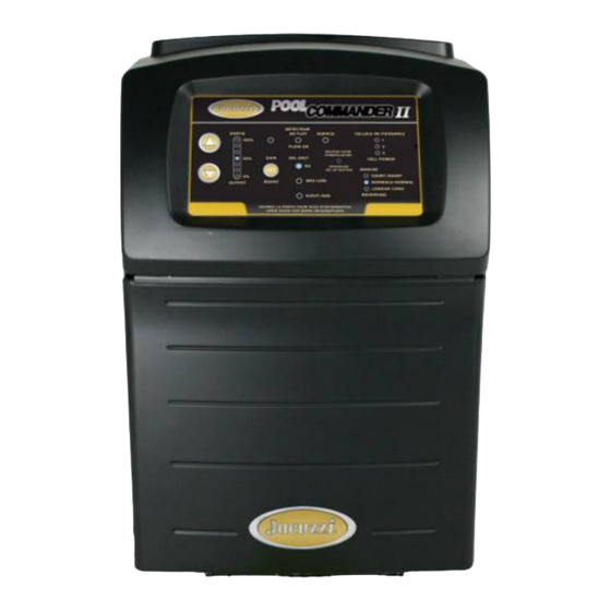
Key Features C o m m a n d e r I I The Control Panel Display provides a J C 5 series of control buttons for OUTPUT level, OUTPUT BOOST mode and SETUP functions, with CELL POWER FLOW-OK SERVICE diagnostic indicator lights for 100% FLOW-OK,... -
Page 11: Pool Water Preparation
Section 3b – OPERATION Pool Water Preparation Salt Requirements It is important that with typical pools, a salt residual of 2.8 – 3.2 g/l (2800 to 3200 ppm) be maintained at all times for peak efficiency. NOTE: Maintaining high salt levels above recommended range can contribute to corrosion of pool/spa equipment. Salt levels exceeding the recommended concentration can be reduced by diluting the pool/spa with fresh water. -
Page 12: Monitoring And Maintenance
Section 3c – OPERATION Monitoring and Maintenance Your Commander II Model JC5 is designed to provide SANITIZER on a daily Water Chemistry Parameters - VERY IMPORTANT NOTE! basis. We recommend the following water chemistry ranges and periodic checks to monitor your systems efficiency. Always follow all local and state requirements. -
Page 13: Service And Maintenance Servicing
Section 3c OPERATION (cont’d) Additional notes: For proper sanitation, spa must be completely drained periodically. The number of days between COMPLETE SPA DRAINAGE is equal to the volume of spa water in liters, divided by 10 times the maximum number of daily spa users. Maximum spa usage temperature is 40°C (104°F). -
Page 14: Servicing
Section 4b –SERVICE and MAINTENANCE Cell The Cell is installed with Unions on each end of the cell to allow quick and easy removal. Loosen the unions and remove the cell from the plumbing. Side View of Cell and Unions VISUAL CELL INSPECTION: The titanium Cell blades, seen inside the Cell body, should be straight and clear of any debris between the blades. -
Page 15: Parts Explosion
Section 4c –SERVICE and MAINTENANCE Parts Explosion Manifold Assembly: Manifold Union w/Strainer: (#941) (#19065) TRI-SENSOR Union Nut Union O-Ring (#19014) Strainer (#19064) CELL w/ UNIONS MANIFOLD UNION w/Strainer MANIFOLD BASE w/Check Valve Electrolytic Cell: (Cell Unions and Cord ordered separately) Red Cap Plug for JC5 cell cord (#19050) 3.6m (12 ft.) Cell Cord (# 952-1) Union O-Ring (#19013) -
Page 16: Section 5 Troubleshooting
Section 5a – TROUBLESHOOTING TROUBLESHOOTING PROBLEM CAUSE SOLUTION Insufficient SANITIZER Production. A) The test kit reagents or test strips are old or expired. A) Retest with new Reagents or Strips. B) The unit is set too low in relation to SANITIZER demand. B) Turn up the output setting. -
Page 17: Appendix Diagnostics
Appendix – BUILT-IN DIAGNOSTICS BUILT-IN DIAGNOSTICS The Commander II Model JC5 Control Box contains a way to display a diagnostic report on its operation. It allows the user to view the salt concentration, the water temperature, and the Electrolytic Cell voltage and amperage. This is provided for a technician to evaluate the performance of the Commander II Model JC5 without the need for special equipment. - Page 18 ****************************** This label transcript service is offered by the Pest Management Regulatory Agency to provide efficient searching for label information. This service and this information do not replace the official hard-copy label. The PMRA does not provide any guarantee or assurance that the information obtained through this service is accurate, current or correct, and is therefore not liable for any loss resulting, directly or indirectly, from reliance upon this service.