Table of Contents
Advertisement
CONTENTS
SAFETY CONSIDERATIONS . . . . . . . . . . . . . . . . . . . . . . 1
GENERAL . . . . . . . . . . . . . . . . . . . . . . . . . . . . . . . . . . . . . . . . 1
INSTALLATION . . . . . . . . . . . . . . . . . . . . . . . . . . . . . . . . 1-17
Step 1 - Receive and Inspect Unit . . . . . . . . . . . . . . . 1
Step 2 - Protect Unit from Damage . . . . . . . . . . . . . . 1
Step 3 - Provide Unit Support . . . . . . . . . . . . . . . . . . . 1
Step 4 - Rig and Place Unit . . . . . . . . . . . . . . . . . . . . . 8
Step 5 - Make Condensate Piping
Connections. . . . . . . . . . . . . . . . . . . . . . . . . . . . . . . . . . . . 8
Step 6 - Install Ductwork . . . . . . . . . . . . . . . . . . . . . . . . 8
Step 7 - Split Systems (Factory Option,
if Required). . . . . . . . . . . . . . . . . . . . . . . . . . . . . . . . . . . . . 8
Step 8 - Make Electrical Connections . . . . . . . . . . 10
• FIELD CONTROL WIRING
• THERMOSTAT WIRE
Step 9 - Adjust Fan Speed . . . . . . . . . . . . . . . . . . . . . 10
START-UP . . . . . . . . . . . . . . . . . . . . . . . . . . . . . . . . . . . . . . . 17
SERVICE . . . . . . . . . . . . . . . . . . . . . . . . . . . . . . . . . . . . . .17,18
SAFETY CONSIDERATIONS
Installing and servicing air-conditioning equipment can be
hazardous due to system pressure and electrical components.
Only trained and qualified service personnel should install,
repair, or service air-conditioning equipment.
Untrained personnel can perform basic maintenance func-
tions such as cleaning coils and filters and replacing filters. All
other operations should be performed by trained service per-
sonnel. When working on air-conditioning equipment, observe
precautions in the literature and on tags and labels attached to
unit.
Follow all safety codes. Wear safety glasses and work
gloves. Use quenching cloth for unbrazing operations. Have
fire extinguisher available.
WARNING
Disconnect all power to the unit before performing mainte-
nance or service. Electrical shock and personal injury could
NOTE: Ensure voltage on unit agrees with voltage listed on
the unit rating plate.
GENERAL
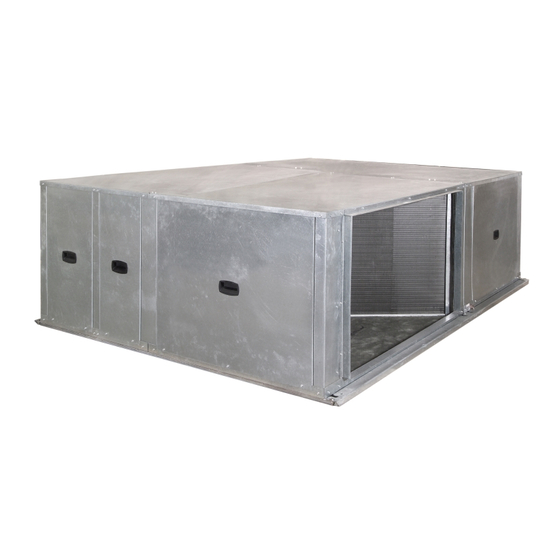
The 50AH024-096 units are single-package, indoor, hori-
zontally mounted air conditioners of 2 to 8 tons capacity. The
50AH units are ASHRAE (American Society of Heating, Re-
frigerating and Air Conditioning Engineers) 90.1 compliant.
These units can be mounted as factory-shipped single-
package units or can be separated and mounted as a split
Manufacturer reserves the right to discontinue, or change at any time, specifications or designs without notice and without incurring obligations.
Catalog No. 04-53500057-01
Horizontal Indoor Single-Package Cooling Units
Installation, Start-Up, and
Service Instructions
Printed in U.S.A.
with PURON
system. If unit is split, the condensing section must be mounted
horizontally.
All units are designed to be ducted on both the condenser
and evaporator sides. Centrifugal blowers are used to ensure
quiet air delivery to the conditioned space. Sound level
requirements should be determined before final unit installa-
tion site is chosen.
Unit servicing is relatively simple since access to the con-
denser and evaporator motors, blowers, belt, and pulley is
gained through access panels located on the sides of the unit.
These panels may also be used for cleaning of condenser coils.
Unit side panels also provide access to control box and pres-
sure switches.
Refrigeration cycle components (e.g., compressor, filter
drier, etc.) can be serviced upon removal of the base unit from
the space.
Determine building alterations required to run piping, wir-
ing, and ductwork. Follow dimensional drawings carefully
for ductwork, piping locations, electrical wiring, and over-
all unit dimensions. Read all installation instructions before
starting installation.
The 50AH units are intended for indoor installation only.
Step 1 - Receive and Inspect Unit -
check unit against shipping order. See Fig. 1 for model number
nomenclature. Inspect carefully for concealed shipping dam-
age. If unit is damaged or incomplete, file claim with transpor-
tation company and advise Carrier immediately.
Step 2 - Protect Unit from Damage -
tain warranty, unit must be protected against theft and vandal-
ism and stored indoors at all times.
Step 3 - Provide Unit Support -
for unit dimensions. Refer to Table 1 for unit sizes and weights.
Each unit requires the following field-supplied items:
8 - threaded suspension rods (
minimum), 4 additional rods are needed if the unit
has a factory-installed air-side economizer
8 - washers
8 - locknuts
Install the 8 field-supplied rods by suspending them from a
suitable ceiling support. Locate rods to mate with 8 outside cor-
ner rigging holes shown in Fig. 2-5. Unit center of gravity is
shown in Fig. 6.
The ceiling and ceiling supports of existing buildings may
require reinforcements; follow all applicable codes.
Form 50AH-14SI
Pg 1
ROOMTOP
50AH024-096
®
Refrigerant (R-410A)
INSTALLATION
WARNING
Refer to Fig. 2-5
3
/
-in.-16 SAE Grade 1
8
5-10
Replaces: 50AH-12SI
®
Unpack and
To main-
Advertisement
Table of Contents

Related Manuals for Carrier ROOMTOP 50AH024-096


Summary of Contents for Carrier ROOMTOP 50AH024-096
-
Page 1: Table Of Contents
Inspect carefully for concealed shipping dam- age. If unit is damaged or incomplete, file claim with transpor- tation company and advise Carrier immediately. Step 2 — Protect Unit from Damage — tain warranty, unit must be protected against theft and vandal- ism and stored indoors at all times. - Page 2 50AH AC 048 5 50AH – Horizontal, Indoor Single-Package Cooling Unit Compressor Options AC – Air Cooled Unit Size - Nominal Tons 024 – 2 060 – 5 036 – 3 072 – 6 048 – 4 096 – 8 Voltage Description 3 –...
- Page 3 a50-8547...
- Page 4 a50-8548...
- Page 5 a50-8549...
- Page 6 a50-8550...
- Page 7 50 equivalent ft, assuming components will be installed in same horizontal plane. If components are not to be installed in same horizontal plane, contact your Carrier representative for more information. For additional piping information, refer to Carrier System Design Manual, Part 3.
-
Page 8: Step 4 - Rig And Place Unit
50 equivalent ft, assuming components will be installed in same horizontal plane. If components are not to be installed in same horizontal plane, contact your Carrier representative for more information. For additional piping information, refer to Carrier System Design Manual, Part 3. - Page 9 For equivalent line lengths greater than 50 ft, contact Carrier for line siz- ing and additional accesories required. IMPORTANT: On units with more than one refrig- erant circuit, be careful not to intermix lines of the various circuits.
-
Page 10: Step 8 - Make Electrical Connections
Install a fused disconnect per NEC. Refer to unit nameplate and Tables 2A-2L for fuse sizes and wire amperages for all units. FIELD CONTROL WIRING — Install a Carrier-approved accessory thermostat assembly according to installation instructions provided by thermostat manufacturer. Locate... - Page 11 Table 2B — Electrical Data — Upgrade 1 Evaporator Motor with Standard Condenser Motor VOLTAGE RANGE UNIT V-PH 50AH (60 Hz) 208/230-1 208/230-1 208/230-3 460-3 208/230-1 208/230-3 460-3 208/230-1 208/230-3 460-3 208/230-1 072* 208/230-3 460-3 208/230-1 096* 208/230-3 460-3 Table 2C — Electrical Data — Upgrade 2 Evaporator Motor with Standard Condenser Motor VOLTAGE RANGE UNIT...
- Page 12 Table 2D — Electrical Data — Upgrade 3 Evaporator Motor with Standard Condenser Motor VOLTAGE RANGE UNIT V-PH 50AH (60 Hz) 208/230-1 208/230-1 208/230-3 460-3 208/230-1 208/230-3 460-3 208/230-1 208/230-3 460-3 208/230-1 072* 208/230-3 460-3 208/230-1 096* 208/230-3 460-3 Table 2E — Electrical Data — Standard Evaporator Motor with Upgrade 1 Condenser Motor VOLTAGE RANGE UNIT...
- Page 13 Table 2F — Electrical Data — Upgrade 1 Evaporator Motor with Upgrade 1 Condenser Motor VOLTAGE RANGE UNIT V-PH 50AH (60 Hz) 208/230-1 208/230-1 208/230-3 460-3 208/230-1 208/230-3 460-3 208/230-1 208/230-3 460-3 208/230-1 072* 208/230-3 460-3 208/230-1 096* 208/230-3 460-3 Table 2G —...
- Page 14 Table 2H — Electrical Data — Upgrade 3 Evaporator Motor with Upgrade 1 Condenser Motor VOLTAGE RANGE UNIT V-PH 50AH (60 Hz) 208/230-1 208/230-1 208/230-3 460-3 208/230-1 208/230-3 460-3 208/230-1 208/230-3 460-3 208/230-1 072* 208/230-3 460-3 208/230-1 096* 208/230-3 460-3 Table 2I —...
- Page 15 Table 2J — Electrical Data — Upgrade 1 Evaporator Motor with Upgrade 2 Condenser Motor VOLTAGE RANGE UNIT V-PH 50AH (60 Hz) 208/230-1 208/230-1 208/230-3 460-3 208/230-1 208/230-3 460-3 208/230-1 208/230-3 460-3 208/230-1 072* 208/230-3 460-3 208/230-1 096* 208/230-3 460-3 Table 2K —...
- Page 16 Table 2L — Electrical Data — Upgrade 3 Evaporator Motor with Upgrade 2 Condenser Motor VOLTAGE RANGE UNIT V-PH 50AH (60 Hz) 208/230-1 208/230-1 208/230-3 460-3 208/230-1 208/230-3 460-3 208/230-1 208/230-3 460-3 208/230-1 072* 208/230-3 460-3 208/230-1 096* 208/230-3 460-3 LEGEND HACR —...
-
Page 17: Start-Up
UNIT SIZE 50AH 1700 0.07 2000 0.11 2500 0.17 3000 0.22 5200 0.68 6400 1.26 LEGEND — Brake Horsepower START-UP Make sure unit has been installed in Unit Preparation — accordance with installation instructions and applicable codes. Compressors are internally Compressor Mounting —... -
Page 18: Service
Refrigerant Charge — Amount of refrigerant charge is listed on unit nameplate (also refer to Table 1). Refer to Carrier GTAC II; Module 5; Charg- ing, Recovery, Recycling, and Reclamation manual. Unit panels must be in place when unit is operating during charging procedure. - Page 20 Copyright 2010 Carrier Corporation Manufacturer reserves the right to discontinue, or change at any time, specifications or designs without notice and without incurring obligations. Catalog No. 04-53500057-01 Printed in U.S.A. Form 50AH-14SI Pg 20 5-10 Replaces: 50AH-12SI...