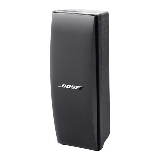
Summary of Contents for Bose 402 Series
- Page 1 ® Series II Loudspeaker ©2009 Bose Corporation Service Manual Reference Number 260431-SM Rev. 02 Electronic copy only...
-
Page 2: Specifications
CORPORATION WHICH IS BEING FURNISHED ONLY FOR THE PURPOSE OF SERVICING THE IDENTIFIED BOSE PRODUCT BY AN AUTHORIZED BOSE SERVICE CEN- TER OR OWNER OF THE BOSE PRODUCT, AND SHALL NOT BE REPRODUCED OR USED FOR ANY OTHER PURPOSE. SPECIFICATIONS... -
Page 3: Main Part List
MAIN PART LIST Item Description Part Number Note Number GRILLE, BLACK 252380-001 GRILLE, ARCTIC WHITE 252380-002 GRILLE, PRO GRAY 252380-004 SCREW, TAPP, 8-15, HEXW, SLOT 290290-12 DRIVER ASSEMBLY, 4.5" 291020-001 GASKET, DRIVER, 4.5" 128407 FOAM, ACOUSTIC, 19.75"x7"x1 120357 CLIP, TINNERMAN 187943 CROSSOVER ASSEMBLY 291042-001... -
Page 4: Packaging Part List
CROSSOVER PCB PART LIST Item Description Part Number Number LAMP, AXIAL LEAD 114462 20uF, CAP, FILM, 75V, 10% 119026 Figure 2. Crossover PCB Layout PACKAGING PART LIST Item Description Part Number Note Number PACKING, FOAM, BOTTOM, EPS 258908 PACKING, FOAM, P/U, RIGHT 258927 PACKING, FOAM, P/U, LEFT 258928... -
Page 5: Disassembly/Assembly Procedures
5. Crossover Removal 2. Grille Replacement 5.1 Remove the three screws (7) securing the 2.1 Rotate the Bose logo (9) 45 so the top driver (1) to the cabinet. Lift out the driver. locking tabs on the logo line up with the slot on the deflector (8). - Page 6 DISASSEMBLY/ASSEMBLY PROCEDURES 6. Crossover Replacement 7.3 Pull out the Speakon connector and remove the wires. 6.1 Replace the two screws (7) securing the crossover PCB (3) to the cabinet. 8. Speakon Connector Replacement 6.2 Perform procedure 4 and 2. 8.1 Referring to figure 1, attach the wires to the Speakon connector (4).
-
Page 7: Test Procedures
TEST PROCEDURES 1. Phase Test noise can be made to go away or get worse, it is a rub or tick and the driver should be 1.1 Observing polarity, apply 9 VDC to the replaced. If the noise stays the same, it is input connector. - Page 8 SERVICE MANUAL REVISION HISTORY Date Revision Description of Change Change Driven By Pages Level Affected 02/01 Document release revision 00 Service manual release 02/06 Added RoHS part numbers This product is now built with RoHS compliant parts. 1/07 No change Corrected part number, Driver Correct part number is Assembly, 4.5”...
- Page 9 Specifications and Features Subject to Change Without Notice Bose Corporation The Mountain Framingham Massachusetts USA 01701 P/N 260431-SM Rev. 02 05/2009 (P) For Technical Assistance or Part Orders, Call 1-800-233-4408 http://serviceops.bose.com...


