
Related Manuals for QSC Q-SYS NL-C4


Summary of Contents for QSC Q-SYS NL-C4
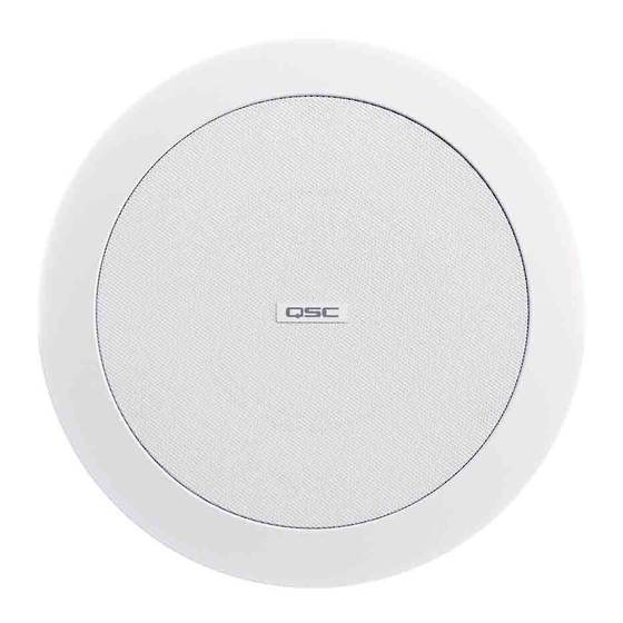
- Page 1 ™ Hardware User Manual NL-C4 4” Full-range, Low-profile Ceiling-mount Network Loudspeaker TD-001637-01-A *TD-001637-01*...
-
Page 2: Important Safety Instructions
QSC authorized service station or an authorized QSC international distributor. QSC is not responsible for any injury, harm or related damages arising from any failure of the customer, owner or user of the apparatus to facilitate those repairs. - Page 3 The QSC Q-SYS NL-C4 is in compliance with European Directive 201 1/65/EU – Restriction of Hazardous Substances (RoHS2). The QSC Q-SYS NL-C4 is in compliance with “China RoHS” directives per GB/T 26572. The following chart is provided for product use in China and its territories: QSC Q-SYS NL-C4 部件名称...
-
Page 4: What's In The Box
What's in the Box (1x) (1x) (1x) (1x) (2x) NL-C4 Cover plate Snap-fit C-ring Telescoping with conduit magnetic tile rails clamp grille (4x) (1x) (1x) (1x) Tile rail Cutout Warranty Safety screws template statement information Connections and Controls ◦ LAN/PoE: RJ-45 connector for Q-SYS Gigabit Ethernet and Power over Ethernet (PoE). Cat5e cabling or better required. PoE+ Type 2 Class 4 capable. ◦... -
Page 5: Installation
Installation Prepare Ceiling Refer to Figure 3. 1. Use the template provided to mark and cut a hole (1) in the ceiling where the loudspeaker is to be installed. For frame-construction ceiling, skip to “Wire the Loudspeakers”. 2. Install two telescoping tile rails (2), one on each side of the hole and supported by the suspended-ceiling support rails (3). 3. - Page 6 Wire the Loudspeakers 1. Back out the conduit cover's Phillips retaining screw to its stop point and pull the conduit cover straight out to remove as shown in step 1 of Figure 4. 2. Pass the CAT cable through the conduit/stress-relief clamp, leaving enough wire for making connections as shown in step 2 of Figure 4. Carefully tighten the clamp over the wires, or over the conduit if used.
- Page 7 Mount the Loudspeaker Refer to Figure 5. 1. Make sure all of the dog-ears are fully extended and in their non-capture position. 2. Position the loudspeaker into the hole prepared in the ceiling. 3. Use a Phillips screwdriver to tighten each of the three dog-ear screws. 4.
-
Page 8: Confirm Connection
Confirm Connection 1. Once the NL-C4 is connected to a suitable PoE/PoE+ network switch or midspan injector, check the LAN/PoE jack LEDs for network status. Left LED Right LED RIGHT LED LEFT LED Yellow Green Dark - Disconnected Dark - Disconnected/10Mbps/100Mbps Solid - Link Solid - 1 Gigabit Link Flashing - Activity... -
Page 9: Customer Support
For a copy of the QSC Limited Warranty, visit the QSC, LLC., website at www.qsc.com. © 2022 QSC, LLC. All rights reserved. QSC and the QSC logo, Q-SYS, and the Q-SYS logo are registered trademarks of QSC, LLC in the U.S. Patent and Trademark Office and other countries.