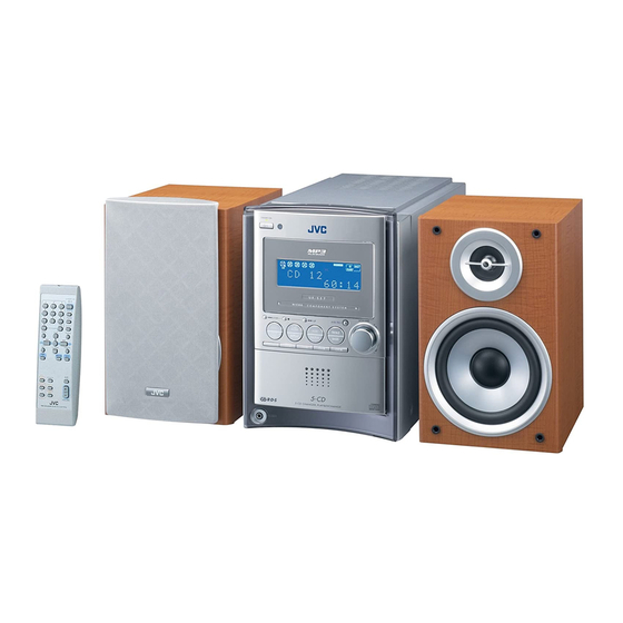
JVC FS-S57 Service Manual
Hide thumbs
Also See for FS-S57:
- Service manual (71 pages) ,
- Instructions manual (32 pages) ,
- Instructions manual (58 pages)
Advertisement
Quick Links
SERVICE MANUAL
COMPACT COMPONENT SYSTEM
4
2004
MB205
1
PRECAUTION. . . . . . . . . . . . . . . . . . . . . . . . . . . . . . . . . . . . . . . . . . . . . . . . . . . . . . . . . . . . . . . . . . . . . . . . . 1-3
2
SPECIFIC SERVICE INSTRUCTIONS . . . . . . . . . . . . . . . . . . . . . . . . . . . . . . . . . . . . . . . . . . . . . . . . . . . . . . 1-6
3
DISASSEMBLY . . . . . . . . . . . . . . . . . . . . . . . . . . . . . . . . . . . . . . . . . . . . . . . . . . . . . . . . . . . . . . . . . . . . . . . 1-7
4
ADJUSTMENT . . . . . . . . . . . . . . . . . . . . . . . . . . . . . . . . . . . . . . . . . . . . . . . . . . . . . . . . . . . . . . . . . . . . . . . 1-30
5
TROUBLESHOOTING . . . . . . . . . . . . . . . . . . . . . . . . . . . . . . . . . . . . . . . . . . . . . . . . . . . . . . . . . . . . . . . . . 1-31
All manuals and user guides at all-guides.com
FS-S57
TABLE OF CONTENTS
COPYRIGHT © 2004 VICTOR COMPANY OF JAPAN, LIMITED
Area suffix
J ----------------------------- U.S.A.
C -------------------------- Canada
No.MB205
2004/4
Advertisement

Related Manuals for JVC FS-S57


Summary of Contents for JVC FS-S57
-
Page 1: Table Of Contents
All manuals and user guides at all-guides.com SERVICE MANUAL COMPACT COMPONENT SYSTEM MB205 2004 FS-S57 Area suffix J ----------------------------- U.S.A. C -------------------------- Canada TABLE OF CONTENTS PRECAUTION............... . . 1-3 SPECIFIC SERVICE INSTRUCTIONS . - Page 2 All manuals and user guides at all-guides.com SPECIFICATION 74 W per channel, min. RMS, driven into 6 Ω at 1 kHz with no more Amplifier Section Output Power CA-FSS57 than 10% total harmonic distortion. Analog input sensitivity/Impedance (at 1 kHz) AUX/DVD:400 mV/48 kΩ 6 Ω...
-
Page 3: Precaution
All manuals and user guides at all-guides.com SECTION 1 PRECAUTION Safety Precautions (1) This design of this product contains special hardware and voltmeter. many circuits and components specially for safety purpos- Move the resistor connection to each exposed metal es. For continued protection, no changes should be made part, particularly any exposed metal part having a return to the original design unless authorized in writing by the path to the chassis, and measure the AC voltage across... - Page 4 All manuals and user guides at all-guides.com Preventing static electricity Electrostatic discharge (ESD), which occurs when static electricity stored in the body, fabric, etc. is discharged, can destroy the laser diode in the traverse unit (optical pickup). Take care to prevent this when performing repairs. 1.5.1 Grounding to prevent damage by static electricity Static electricity in the work area can destroy the optical pickup (laser diode) in devices such as laser products.
- Page 5 All manuals and user guides at all-guides.com Importance administering point on the safety Primary board F1000 2.5A-125V Caution: For continued protection against risk of fire, replace only with same type 2.5 A/125 V for F1000, 1.5 A/125 V for F1001. This symbol specifies type of fast operating fuse.
-
Page 6: Specific Service Instructions
All manuals and user guides at all-guides.com SECTION 2 SPECIFIC SERVICE INSTRUCTIONS This service manual does not describe SPECIFIC SERVICE INSTRUCTIONS. 1-6 (No.MB205) -
Page 7: Disassembly
All manuals and user guides at all-guides.com SECTION 3 DISASSEMBLY Main body section 3.1.1 Removing the metal cover (See Figs.1 to 3) (1) From the back side of the main body, remove the six screws A attaching the metal cover. (See Fig.1.) Metal cover (2) From the both sides of the main body, remove the two screws B attaching the metal cover. - Page 8 All manuals and user guides at all-guides.com 3.1.2 Removing the front panel assembly (See Figs.4 to 6) • Remove the metal cover. Front panel assembly (1) From the left side of the main body, disconnect the wire from the connector CN104 on the power supply board.
- Page 9 All manuals and user guides at all-guides.com 3.1.3 Removing the rear panel (See Fig.7) • Remove the metal cover. Rear panel (1) From the back side of the main body, remove the five screws E attaching the rear panel. (2) Remove the screw F attaching the rear cover. (3) Remove the rear panel from the chassis while extending the sections d of the rear panel in the direction of the arrow.
- Page 10 All manuals and user guides at all-guides.com 3.1.6 Removing the micon board (See Figs.9 and 10) • Remove the metal cover, front panel assembly and rear panel. (1) From the top side of the main body, disconnect the card wire from the connector CN766 on the micon board.
- Page 11 All manuals and user guides at all-guides.com 3.1.7 Removing the power amplifier board (See Fig.11) • Remove the metal cover, front panel assembly, rear panel, power supply board and micon board. Power amplifier board (1) From the top side of the main body, remove the wire holder Wire 2 and tie band fixing the wire 1.
- Page 12 All manuals and user guides at all-guides.com 3.1.9 Removing the fan (See Fig.14) • Remove the metal cover, front panel assembly, rear panel, power supply board, micon board and power amplifier board. Wire holder (1) From the back side of the main body, remove the wire hold- er fixing the wire.
- Page 13 All manuals and user guides at all-guides.com 3.1.11 Removing the CD changer mechanism assembly (See Figs.16 to 19.) • Remove the metal cover and front panel assembly. CD bracket (F) (1) From the right side of the main body, disconnect the card wire from the connector CN651 on the CD servo control...
- Page 14 All manuals and user guides at all-guides.com Front panel assembly • Remove the metal cover and front panel assembly. 3.2.1 Removing the front assembly section (See Fig.20) (1) From the inside of the front panel assembly, remove the Front assembly section screw U attaching the earth wire.
- Page 15 All manuals and user guides at all-guides.com 3.2.3 Removing the back light board (See Figs.23) • Remove the front assembly section. (1) From the inside of the front assembly section, remove the Back light board six screws X attaching the back light board. (2) Take out the back light board from the front assembly sec- tion and disconnect the card wires from the connectors (CN551,CN552) on the back light board.
- Page 16 All manuals and user guides at all-guides.com 3.2.4 Removing the FL board (See Figs.24 and 25) • Remove the front assembly section and back light board. LED lens Front assembly section (1) From the inside of the front assembly section, remove the four screws Y attaching the lens holder.
- Page 17 All manuals and user guides at all-guides.com 3.2.5 Removing the headphone jack board (See Fig.26) (1) From the inside of the front panel assembly, remove the Front panel assembly screw Z attaching the headphone jack board. Wire (2) Take out the headphone jack board from the front panel as- sembly.
- Page 18 All manuals and user guides at all-guides.com CD changer mechanism 3.3.1 Removing the tray assembly (See Fig.1 ~ 5) Open det lever (1) Remove the two screws A from the top cover and release the two joints a on both sides of the body. (2) Remove the top cover with the two rods attached to the top cover and lifter assembly respectively.
- Page 19 All manuals and user guides at all-guides.com 3.3.2 Removing the servo control board Card wire (See Fig.6 ~ 9) Caution: Short round Solder the short-circuit point on the pickup before disconnect- ing the card wire extending from the pickup. If you do not follow this instruction, the pickup may be damaged.
- Page 20 All manuals and user guides at all-guides.com 3.3.4 Removing the motor board (See Fig.10 , 11) • Prior to performing the following procedure, remove the servo control board. (1) Turn over the body and remove the two screws D. Move the CD module bkt.
- Page 21 All manuals and user guides at all-guides.com 3.3.5 Removing the CD tramecha assembly (See Fig.12) • Prior to performing the following procedure, remove the servo control board. (1) Turn over the body and remove the three screws F attach- ing the tramecha. CD Tramecha assembly Fig.12 (No.MB205)1-21...
- Page 22 All manuals and user guides at all-guides.com 3.3.6 Removing the pickup (See Fig.13 , 14) Mecha base • Prior to performing the following procedure, remove the servo Pickup assembly control board and CD tramecha assembly. (1) From top of the CD tramecha assembly, turn the cam gear in the direction of the arrow to move the pickup assembly outward.
- Page 23 All manuals and user guides at all-guides.com 3.3.7 Removing the side (L)/ tray switch board (See Fig.15 ~ 17) • Prior to performing the following procedure, remove the tray assembly. (1) Remove the two screws H attaching the side (L) on top of the body.
- Page 24 All manuals and user guides at all-guides.com 3.3.8 Removing the side (R) assembly Side (R) assembly (See Fig.18 ~ 22) • Prior to performing the following procedure, remove the tray assembly. (1) Push and release the two tabs m of the gear cover through the two notches inside the side (R) assembly.
- Page 25 All manuals and user guides at all-guides.com 3.3.9 Removing the lifter assembly Hook (See Fig.23 ~ 27) • Prior to performing the following procedure, remove the tray assembly and side (L)/ side (R) assembly. (1) From top of the body, turn the 1 gear clockwise to move the lifter assembly upward as shown in Fig.24.
- Page 26 All manuals and user guides at all-guides.com 3.3.10 Removing the rack holder assembly/ sensor assembly (See Fig.28 ~ 33) • Prior to performing the following procedure, remove the tray 1 gear assembly, side (L)/ side (R) assembly, lifter assembly. Attention: If the slide gear of the body places at joint w of the rack holder assembly, turn the 1 gear counterclockwise to move the slide gear toward the front.
- Page 27 All manuals and user guides at all-guides.com Sensor board Soldering point SV resister Sensor assembly Sensor braket Sensor slider Fig.32 Spring Sensor assembly Fig.30 Sensor slider Spring Slide gear Fig.31 Slide lever Spring Fig.33 (No.MB205)1-27...
- Page 28 All manuals and user guides at all-guides.com 3.3.11 Removing the motor (See Fig.34 ,35) • Prior to performing the following procedure, remove the servo control board and top cover. Attention: You need not to remove the tray assembly, and in such case, move it.
- Page 29 All manuals and user guides at all-guides.com 3.3.12 Taking out the CD in play mode Tray assembly (See Fig.36 ~ 39) Attention: Refer to “Removing the tray assembly”. (1) Remove the top cover upward. (2) Unlock the tray assembly and draw out the tray assembly toward the front.
-
Page 30: Adjustment
All manuals and user guides at all-guides.com SECTION 4 ADJUSTMENT This service manual does not describe ADJUSTMENT. 1-30 (No.MB205) -
Page 31: Troubleshooting
All manuals and user guides at all-guides.com SECTION 5 TROUBLESHOOTING This service manual does not describe TROUBLESHOOTING. (No.MB205)1-31... - Page 32 All manuals and user guides at all-guides.com VICTOR COMPANY OF JAPAN, LIMITED AV & MULTIMEDIA COMPANY AUDIO/VIDEO SYSTEMS CATEGORY 10-1,1chome,Ohwatari-machi,Maebashi-city,371-8543,Japan (No.MB205) Printed in Japan...
- Page 33 All manuals and user guides at all-guides.com SCHEMATIC DIAGRAMS COMPACT COMPONENT SYSTEM FS-S57 CD-ROM No.SML200404 Area suffix J ----------------------------- U.S.A. C -------------------------- Canada Contents Block diagram Standard schematic diagrams 2-15 to 20 Printed circuit boards No.MB205SCH COPYRIGHT 2004 VICTOR COMPANY OF JAPAN, LTD.
- Page 34 All manuals and user guides at all-guides.com In regard with component parts appearing on the silk-screen printed side (parts side) of the PWB diagrams, the parts that are printed over with black such as the resistor ( ), diode ( ) and ICP ( ) or identified by the "...
- Page 35 All manuals and user guides at all-guides.com < M E M O >...
- Page 36 All manuals and user guides at all-guides.com Block diagram FM/AM tuner unit section Signal processing and system FM ANT FM/AM TUNER TUDIN AM ANT TUDOUT Q7600 CE,CLK Q7601 TUNER CD servo and CD system control section SWITCH TBAL,FBAL TE,FE,GCTL /RFDET IC601 OFT,BDO LD,MD...
- Page 37 All manuals and user guides at all-guides.com d system control section SPEAKER OUTPUT Q7801 Q7802 Power transformaer Primary section RY200 SPEAKER Q7600 CIRCUIT T1101 Q7601 TRANS INPUT TUNER H/PSW T1100 INHB SWITCH TRANS SPKRLY OUTL OUTR FTUNER CN102 Q1100 Q1200 to Q1202 DIODE US6V REG.
- Page 38 All manuals and user guides at all-guides.com Standard schematic diagrams Primary and power amplifier section IC340 STK432-070 C3102 C3105 C3118 R3100 4.7K 10/35 100P 100P R3115 R3123 D3100 D3104 MTZJ9.1B-T2 C3103 MTZJ9.1B-T2 R3101 4.7K 10/35 Q3105 C3113 C3116 R3108 KTC3199/GL/-T C3104 R3127 R3137...
- Page 39 All manuals and user guides at all-guides.com EP300 QNZ0136-001Z B1602 B1601 S1AC1 S1AC2 C1300 C1400 S2AC1 0.1/50 S2AC2 0.1/50 AMPG D1300 D1400 1N5402M-20 1N4003S-T5 D1500 D1302 US10V R1501 D1402 1N5402M-20 1N4003S-T5 US6V POUTRLY C1302 C1402 INHB 0.1/50 H/PR 0.1/50 H/PGND H/PL H/PSW T1101...
- Page 40 All manuals and user guides at all-guides.com Signal processing and system control section QNN0420-001 J2100 C2102 0.001 D2100 R2116 6.2K D2101 SIGR 220P 220P C2100 C2101 C2126 0.018 100K R2147 R2102 R2103 Q2211 IC901 2SC2001/K/-T LC75345M-X VOLCK VOLDA 2.2K VOLCE R2224 C2026 0.018...
- Page 41 All manuals and user guides at all-guides.com (SHEET 6) QGF1201F3-11 CN766 C2702 0.001 B2712 C7601 4.7/50 C7600 Q7601 UN2211-X R7601 LC72723 IC760 C7602 C7616 220/10 L7600 C7608 B2662 R7606 SDATAIN POWERKEY TUCLK SDATAOUT LEDGREEN TUCE C7551 100/16 LEDRED KEY0 FL5V DGND VOLM MMOD...
- Page 42 All manuals and user guides at all-guides.com FL display / Users key control / Source selector switch section IC520 GP1UM281XK US5V POWERKEY D5200 LEDGREEN US5V SPR-39MVWF LEDRED POWERKEY LEDGREEN DGND LEDRED FL5V VOLM FLVH KEY2 KEY1 VOLP D5400 D5401 D5402 FLDATA SELU1E10WXM-P SELU1E10WXM-P...
- Page 43 All manuals and user guides at all-guides.com QJK036-042104 W5600 L5600 J5600 QNS0170-001 H/PSW QQL231K-470Y H/PL K5600 H/PGND H/PR QQR0621-001Z L5601 QQL231K-470Y R5100 R5101 R5102 R5103 R5104 R5105 R5106 R5107 R5108 1.2K 1.5K 2.2K 2.7K 3.9K 5.6K R5116 R5115 R5114 R5113 R5112 R5111 R5110...
- Page 44 All manuals and user guides at all-guides.com CD servo and CD system control section CN251 QGF1036F1-15 TR3_CL TR2_CL TR4_CL TR1_CL TR5_CL S.TR_ST C201 M.TR_OP 0.1/16 (SHEET 5) POS_UP TR_OP POS_DOWN BR24C08FV-X R601 5.6k TBAL TR_CL C603 FBAL 0.1/16 R602 TP622 3.9k C604 0.1/16...
- Page 45 All manuals and user guides at all-guides.com C201 CN653 0.1/16 BR24C08FV-X R283 R282 COPY R267 TXTCK IC251 /DR_MUTE TXTD CN651 QGF1036F1-17 EQX5 R281 TXD0 EQX2 MN101C61GMB1 /RST_DSP RXD0 R271 EQX4 TP272 FLAG R274 DQSY R285 S.TR_END BLKCK M.TR_OP R286 TR5_CL R287 R264 POS_DOWN...
- Page 46 All manuals and user guides at all-guides.com CD tray control section QSW0931-001 M.TR_OP TR5_CL TR5_CL TR4_CL TR4_CL TR3_CL TR3_CL TR2_CL TR2_CL TR1_CL TR1_CL 0.1/50 QRA0164-001 2-11...
- Page 47 All manuals and user guides at all-guides.com QVY0002-B14 WJM0331-001A QSW0886-002 WJM0330-001A LB1641 LB1641 TR3_CL TR2_CL TR4_CL TR1_CL TR5_CL M.TR_OP POS_UP TR_OP POS_DOWN TR_CL 1/50 0.1/50 QSW0886-002 0164-001 QRA0164-001 SHEET 5 2-12...
- Page 48 All manuals and user guides at all-guides.com FM / AM tuner unit section 0.01u 0.01u KTC4081 4.7u 5.6k 0.47u 0.01u 100k 2200p 120u 1.5p 0.01u 2-13...
- Page 49 All manuals and user guides at all-guides.com DTA114EUA 47/50 2.2k 330p 0.022u 75KHz 2200p ALP038 100p 100P 0.47u PCFAZ-105 2.2/50 2.2/50 0.01u 0.027u SHEET 6 2-14...
- Page 50 All manuals and user guides at all-guides.com Printed circuit boards Micon board (Micon board) R7661 R2930 R7777 R2908 VR290 R2907 K2900 W792 C2902 R7248 C7610 R2931 CN777 CN766 CN790 IC902 R7551 Q7550 C2900 D7551 R7018 R7028 C7228 R7214 R2113 R7606 Q7600 R7241 C2117...
- Page 51 All manuals and user guides at all-guides.com R7660 C2600 C2703 R2942 R2933 D2600 R2943 CN760 C2611 C2610 R2111 C2110 D2602 C2114 C2111 C2107 C2115 C2108 C2602 R2110 C2109 R2100 Q2602 C2126 D2601 R2102 C2100 R2040 J2100 C2118 C2119 C2116 R2041 D2603 IC901 D2604...
- Page 52 All manuals and user guides at all-guides.com Power board (Power amplifier board) PP300 CN350 C3002 C3000 C3001 R3128 C3123 IC342 IC343 IC341 IC340 TH332 R3122 R3114 R3136 Q3105 Q3106 C3301 R3135 C3126 R3109 C3116 C3113 D3300 R3134 C3304 D3302 R3302 C3112 C3122 Q3107...
- Page 53 All manuals and user guides at all-guides.com (Primary board) D1500 D1501 R1502 C1500 Q1500 CN102 D1200 R1200 Q1201 R1202 C1201 Q1202 CN104 C1200 R1101 PP100 Q1100 CN103 C1600 2-18...
- Page 54 All manuals and user guides at all-guides.com CD servo board (Forward side) CN252 CN253 IC201 CN251 C259 R267 IC251 R257 R278 R283 R284 R281 R256 R282 R285 R286 R287 R288 R264 C633 R289 R263 R290 R291 R292 R635 R262 R607 R261 R258 CN601...
- Page 55 All manuals and user guides at all-guides.com Loading switch board (Motor board) (Tray switch board) (Switch board) (Sensor board) 2-20...
- Page 56 All manuals and user guides at all-guides.com VICTOR COMPANY OF JAPAN, LIMITED AV & MULTIMEDIA COMPANY AUDIO/VIDEO SYSTEMS CATEGORY 10-1,1chome,Ohwatari-machi,Maebashi-city,371-8543,Japan Printed in Japan (No.MB205SCH)
- Page 57 All manuals and user guides at all-guides.com PARTS LIST [ FS-S57 ] * All printed circuit boards and its assemblies are not available as service parts. Area suffix J ----------------------------- U.S.A. C -------------------------- Canada - Contents - 3- 2 Exploded view of general assembly and parts list (Block No.M1) 3- 5 CD changer mechanism assembly and parts list (Block No.MA)
- Page 58 All manuals and user guides at all-guides.com Exploded view of general assembly and parts list Block No. Power supp 4 4 4 Back light board Switch board FL board Headphone jack board...
- Page 59 All manuals and user guides at all-guides.com Power supply board Power amplifier board Micon board...
- Page 60 All manuals and user guides at all-guides.com General assembly Block No. [M][1][M][M] Symbol No. Part No. Part Name Description Local Symbol No. Part No. Part Name Description Local GV10149-018A REAR PANEL GV20232-002A REAR COVER GV10225-006A FRONT PANEL QYSBSGY3008E SPECIAL SCREW 3mm x 8mm(x2) GV10143-009A...
- Page 61 All manuals and user guides at all-guides.com CD changer mechanism assembly and parts list Block No. FMU-SC6-2M Grease =JVG-31N =JVS-1003...
- Page 62 All manuals and user guides at all-guides.com CD changer mechanism Block No. [M][A][M][M] Symbol No. Part No. Part Name Description Local LV10743-004A CHASSIS ASSY LV43278-001A SENSOR SPRING LV33961-002A SENSOR SLIDER LV33962-001A SENSOR BRACKET QYSDST2605Z SCREW 2.6mm x 5mm(x2) QVY0027-B14 S V RESISTOR QYSDST2004Z SCREW...
- Page 63 All manuals and user guides at all-guides.com CD mechanism assembly and parts list Block No. Grease & Bond FXL-M75T-2M = JVG-31N CD mechanism Block No. [M][B][M][M] Symbol No. Part No. Part Name Description Local Symbol No. Part No. Part Name Description Local QAR0253-001...
- Page 64 All manuals and user guides at all-guides.com Electrical parts list Micon board Block No. [0][1][0][0] Symbol No. Part No. Part Name Description Local Symbol No. Part No. Part Name Description Local C2105 QETN1HM-475Z E CAPACITOR 4.7uF 50V M C2107 QTE1V06-106Z E CAPACITOR...
- Page 65 All manuals and user guides at all-guides.com Symbol No. Part No. Part Name Description Local Symbol No. Part No. Part Name Description Local R2016 NRSA63J-622X MG RESISTOR 6.2kΩ 1/16W J R7056 NRSA63J-122X MG RESISTOR 1.2kΩ 1/16W J R2017 NRSA63J-182X MG RESISTOR 1.8kΩ...
- Page 66 TRANSISTOR C3125 QETN1HM-226Z E CAPACITOR 22uF 50V M Q3100 KRA102M-T DIGI TRANSISTOR C3126 QETN1VM-476Z E CAPACITOR 47uF 35V M Q3101 2SC3576-JVC-T TRANSISTOR C3200 QETN1HM-475Z E CAPACITOR 4.7uF 50V M Q3102 2SC3576-JVC-T TRANSISTOR C3300 QETN1HM-106Z E CAPACITOR 10uF 50V M Q3103...
- Page 67 All manuals and user guides at all-guides.com Symbol No. Part No. Part Name Description Local Symbol No. Part No. Part Name Description Local R3110 QRJ146J-100X UNF C RESISTOR 10Ω 1/4W J IC251 MN101C61GMB3 R3111 QRJ146J-100X UNF C RESISTOR 10Ω...
- Page 68 All manuals and user guides at all-guides.com Symbol No. Part No. Part Name Description Local Symbol No. Part No. Part Name Description Local R262 NRSA63J-102X MG RESISTOR 1kΩ 1/16W J R806 NRSA63J-332X MG RESISTOR 3.3kΩ 1/16W J R263 NRSA63J-102X MG RESISTOR 1kΩ...
- Page 69 All manuals and user guides at all-guides.com < MEMO > 3-13...
- Page 70 All manuals and user guides at all-guides.com Packing materials and accessories parts list Block No. A4,A5,A6, A7,A8,A9 3-14...
- Page 71 All manuals and user guides at all-guides.com Packing and accessories Block No. [M][3][M][M] Symbol No. Part No. Part Name Description Local GVT0134-002A INST BOOK ENG,FRE S57C GVT0134-001B INST BOOK S57J RM-SFSS57J REMOCON UNIT ------------------ BATTERY (x2) BT-51028-2 REGISTER CARD S57J YU20333 SAFETY INST.