Table of Contents
Advertisement
Advertisement
Table of Contents

Related Manuals for Burnham BOILERS


Summary of Contents for Burnham BOILERS
- Page 1 Price - $3.00 INSTALLATION, OPERATING AND SERVICE INSTRUCTIONS FOR RSA BOILERS...
- Page 2 All wiring on boilers installed in the USA shall be made in accorda nce with the National Electrical Code and/or Loc al Regul ations. Al l wiring on boilers installed in Canada shall be made in ac corda nce with the Canadian Electrical Code and/or Loc al Regulations.
- Page 3 (avai lable at extra cost). Do not ins tall boiler on carpeting. Do not tam per wi th or alter the boiler or controls. Re tain your cont ra ctor or a compet ent se rv ice man to assure that th e unit is p ro perly adjus ted an d main taine d.
- Page 4 (i. e. wood, coal) or gaseous fuel (i. e. natural gas, LP/propane). All flammable debris, rags, paper, wood scraps, etc., should be kept clear of the boiler at all times. Keep the boiler area clean and free of fire hazards.
-
Page 5: Table Of Contents
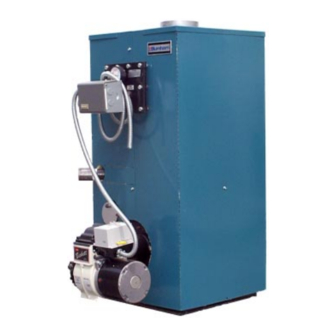
III. Water Piping and Trim ... 12 IV. Venting ... 18 Electrical and Sequence of Operation 20 Figure 1: RSA Packaged Boiler (RSA85 / RSA135) VI. Oil Piping ... 28 VII. System Start-Up ... 30 VIII. Service and Cleaning ... 36... - Page 6 Figure 1A: RSA Packaged Boiler (RSA170 / RSA285) Boiler B are Boiler Model A ssem bly Num ber RS A170 WV-29-10 RS A195 WV-29-13A RS A240 WV-29-16A RS A285 WV-29-19A M inim um Chimney Sizes In. x In. x Ft.
-
Page 7: I. Pre-Installation
1. Listed clearances comply with American National Standard ANSI/NFPA 31, Installation of Oil Burning Equipment. 2. RSA boilers can be installed in rooms with clearances from combustible material as listed above. Listed clearances can not be reduced for alcove or closet installations. -
Page 8: Provide Combustion/Ventilation
The opening or duct must be sized so the boiler input will not exceed 4,000 BTUH/Sq. In. of free area. If other air consum- ing appliances are near the boiler, the air inlet should be larger. -
Page 9: Ii. Knockdown Boiler Assembly
. REMOVAL OF BOILER. 1. Remove, all boiler to skid, hold down fasteners. Refer to Figure 3. 2. Carefully walk boiler to the edge of skid. Tilt the boiler back, allowing an edge to rest on the floor, and remove the skid. - Page 10 Figure 5: Burner Mounting...
- Page 11 Figure 6: RSA Jacket Assembly...
-
Page 12: Iii. Water Piping And Trim
Oxyge n c onta mination of boi ler water will cause corrosion of iron a nd s te el boiler c ompone nts , and can lead to boiler failure. Burnham's Standard Warranty does not cover problems caused by oxy ge n contamination of boiler water or scale (lime ) bui ld-up c aused by freque nt addition of w ater. - Page 13 . After the boiler and system have been cleaned and flushed, and before refilling the entire system add appropriate water treatment chemicals, if necessary, to...
- Page 14 Figure 8: Recommended Boiler Piping for Circulator Zoned Heating Systems...
- Page 15 Figure 9: Boiler Piping for Zone Valve Zoned Heating Systems...
- Page 16 . CONNECT TANKLESS HEATER PIPING AS SHOWN IN FIGURE 11. See Table 1 for Tankless Heater Rating. WARNING Install automatic mixing v alve at tankless hea ter outle t to av oid ris k of burns or scalding due to ex cessive ly hot water at fixtures.
- Page 17 Figure 11: Schematic Tankless Heater Piping Table 1: Tankless Heater Ratings Boiler Model RSA(H)85 & 110 RSA110(H)125 & 135 RSA125 & 135 Boiler Model RSA170 RSA195, 240, & 285 S350 S375 PSID 3½ 3¼ 3¾ 3½ STD. #7524 OPT. #7530 PSID 3¾...
-
Page 18: Iv. Venting
That probably means that the stack temperature from the new boiler will be lower than that from the old boiler and with less room air being drawn up the chimney to dilute the stack gases. The combina-... - Page 19 Figure 12: Recommended Smokepipe Arrangement and Chimney Requirements Figure 13: Draft Regulator Locations...
- Page 20 Positively assure all electrical connecti ons are unpow ered before attempting installation or service of elec tric al components or connections of the boiler or bui lding. Lock out all ele ctrical boxes wi th pa dlock once power is turned off.
- Page 21 Figure 14: “RSAL” Wiring Less Tankless, Single Circulator Figure 15: “RSAT” or “RSAR” Wiring with Tankless, Single Circulator...
- Page 22 Figure 16: Circulator Zoned Wiring for Honeywell R8888...
- Page 24 Figure 18: Different Manufacturer’s Zone Valve Connections to Honeywell R8889...
- Page 25 The Burnham EC50 00 Control includes a water temperature sensor. Mount this sensor to the sys te m s upply piping. 8. Burnham EC5000 Circulator Zoned System – Refer to Figure 19 of this manual for the electrical diagram for this type of system. Wire the system as indicated in that diagram.
- Page 26 Figure 19: Circulator Zoning with EC5000 Wiring Schematic...
-
Page 28: Vi. Oil Piping
VI. Oil Piping . General. 1. Use flexible oil line(s) so that burner can be removed without disconnecting the oil supply. 2. A supply line fuel oil filter is recommended as a minimum for all firing rates but a pleated paper fuel oil filter is recommended for the lowest firing rate application to prevent nozzle fouling. - Page 29 TABLE 2: SINGLE STAGE UNITS (3450 RPM) TWO PIPE SYSTEMS Maximum Length of Tubing "H" +"R" (See Figure) Lift "H" (See Figure) 3/8" OD Tubing (3 GPH) TABLE 3: TWO-STAGE UNITS (3450 RPM) Lift "H" (See Figure) 1/2" OD Tubing (3 GPH) 100' 100' 100'...
-
Page 30: Vii. System Start-Up
12 psig. 10. Open isolation valve in boiler supply piping. 11. Remove hose from bib cock. CONFIRM that the boiler and system have no water leaks. . CHECK CONTROLS, WIRING AND BURNER to be sure that all connections are tight and burner is rigid. - Page 31 ADJUST OIL PRESSURE 1. Locate oil pressure adjusting screw and turn screw until Pressure Gauge reads the correct pump pressure required for the specific boiler. Refer to table 4 & 4A. 2. DO NOT REMOVE PRESSURE GAUGE until later.
- Page 32 The selection of the nozzle supplied with the RSA boiler is the result of extensive testing to obtain the best flame shape and efficient combustion. Other brands of the same spray angle and spray...
- Page 33 It chills the flame, causes smoke, and allows unburned fuel to pass through the combustion chamber and clog the flueways of the boiler. h. COLD OIL— If the oil temperature approach- ing the fuel pump is 40°F or lower, poor combustion or delayed ignition may result.
- Page 34 Both can result in reduced boiler life. The accumulation of sediment can eventually isolate the water from contacting the steel. When this happens the steel in that area gets extremely hot and eventually cracks.
- Page 35 INSTALLATION INSTRUCTIONS FOR SHIELD REQUIRED FOR COMBUSTIBLE FLOOR This shield for combustible floors is intended for use only with the following Burnham oil-fired boilers: Use Part Number 6183504 for the following models: RSA(H)85 ADDS 4-3/16” TO BOILER HEIGHT Use Part Number 6183505 for the following models: RSA170 ADDS 5-3/8”...
-
Page 36: Viii. Service And Cleaning
Assemble the boiler in reverse order. Units should be cleaned at least once a year, preferably at the end of each heating season. It is not necessary to remove burner to clean boiler. Brush, scrape, or vacuum from top. Figure 25: Cleaning of RSA Boiler off. -
Page 37: Ix. Repair Parts
All RSA Repair Parts may be obtained through your local Burnham Wholesale distributor. Should you require assistance in locating a Burnham distributor in your area, or have questions regarding the availability of Burnham products or repair parts, please contact your Burnham Regional Sales Office as listed below. - Page 38 REPAIR PARTS NOTE: When ordering parts always give the serial number and model number shown on the boiler. Also provide the name of the part(s) shown below:...
- Page 39 1/2" Thick x 2" x 13-3/4" Cerafelt Strip 1/2" Thick x 2" x 18-1/2" Cerafelt Strip Combustion Chamber Cerablanket Base Assembly Machine Screw, Hex Head, 1/4 - 2 x 1/4" Hex Nut, 1/4 - 20 (Heavy Hex) BOILER MODEL DESCRIPTION RSA85 RSA110 RSA125 RSA135 PART NO.
- Page 40 NOTE: When ordering parts always give the serial number and model number shown on the boiler. Also provide the name of the part(s) shown below: Figure 27: RSA170-285 Boiler Repair Parts...
- Page 41 Block Insulation Assembly Jacket Left S ide Panel Assembly Jacket Upper Front Panel Assembly Jacket Lower Front Panel Assembly Base Assembly Jacket Rear Panel Assembly Jacket Right S ide Panel Assembly Boiler Model DESCRIPTION for Quantity RSA170 6306332 RSA195 6306329...
- Page 42 ITEM Jacket Wrap-A-Round Panel, RSA85/110 Jacket Wrap-A-Round P anel, RSA125/135 Temperature / P ressure Gauge Honeywell L8148A1090 Hi-Limit Control Honeywell L8124C1102 Limit Control Observation Port Cover / Hardware Burner Primary Control, R4184D1027 DESCRIPTION Jacket Top Panel PART NUMBER 60435086 60435087 60435088 8056169U 80160449U...
- Page 43 SERVICE SCHEDULE DATE SERVICE PERFORMED...
- Page 44 FOR REPLACEMENT OIL BURNER PARTS, CONTACT YOUR WHOLESALER OR THE BURNER MANUFACTURER: NOTE: When ordering parts always give the serial and model numbers shown on the boiler and burner. Also, provide the name of the part(s) and part(s) number as listed below.
- Page 45 Ordering Information for Quality Replacement Parts Figure 29: BECKETT AFG MODEL BURNER...
- Page 46 BECKETT BURNER PARTS LIST FOR RSA SERIES STEEL BOILERS FOR REPLACEMENT OIL BURNER PARTS, CONTACT YOUR WHOLESALER OR THE BURNER MANU- FACTURER: Boiler Model Burner Model Air Tube Combination Spec. No. Air Band Air Band Nut Air Band Screw Air Shutter...
- Page 47 Ordering Information for Quality Replacement Parts Figure 30: BECKETT AF and SF MODEL BURNERS...