Table of Contents
Advertisement
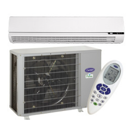
40QNC / 38HDF
40QNQ / 38QRF
High---Wall Duct Free Split System
Sizes 018 to 036
40QNC, QNQ Unit
NOTE: Read the entire instruction manual before starting the
installation.
WARNING
!
UNIT OPERATION AND SAFETY HAZARD
Failure to follow this warning could result in personal injury or
equipment damage.
Puron refrigerant systems operate at higher pressures than
standard R- -22 systems.
possible personal injury, do not use R- -22 service equipment or
components on Puron refrigerant equipment.
Installation Instructions
To avoid damage to the unit or
SAFETY CONSIDERATIONS
Improper installation, adjustment, alteration, service, maintenance,
or use can cause explosion, fire, electrical shock, or other
conditions which may cause death, personal injury, or property
damage. Consult a qualified installer, service agency, or your
distributor or branch for information or assistance. The qualified
installer or agency must use factory- -authorized kits or accessories
when modifying this product. Refer to the individual instructions
packaged with the kits or accessories when installing.
Follow all safety codes. Wear safety glasses, protective clothing,
and work gloves. Use quenching cloth for brazing operations.
Have fire extinguisher available. Read these instructions
thoroughly and follow all warnings or cautions included in
literature and attached to the unit. Consult local building codes and
current editions of the National Electrical Code ( NEC ) NFPA 70.
In Canada, refer to current editions of the Canadian electrical code
CSA 22.1.
Recognize safety information. This is the safety- -alert symbol
When you see this symbol on the unit and in instructions or
manuals, be alert to the potential for personal injury. Understand
these signal words; DANGER, WARNING, and CAUTION. These
words are used with the safety- -alert symbol. DANGER identifies
the most serious hazards which will result in severe personal injury
or death. WARNING signifies hazards which could result in
personal injury or death. CAUTION is used to identify unsafe
practices which would result in minor personal injury or product
and property damage. NOTE is used to highlight suggestions
which will result in enhanced installation, reliability, or operation.
WARNING
!
ELECTRICAL SHOCK HAZARD
Failure to follow this warning could result in personal
injury or death.
Before installing, modifying, or servicing system, main
electrical disconnect switch must be in the OFF
position. There may be more than 1 disconnect switch.
Lock out and tag switch with a suitable warning label.
CAUTION
!
PERSONAL INJURY AND EQUIPMENT DAMAGE
HAZARD
Failure to follow this caution may result in personal injury
and / or equipment damage.
DO NOT operate the unit without a filter or with grille
removed.
! !
Advertisement
Table of Contents

Related Manuals for Carrier 40QNC


Summary of Contents for Carrier 40QNC
-
Page 1: Installation Instructions
40QNC / 38HDF 40QNQ / 38QRF High---Wall Duct Free Split System Sizes 018 to 036 Installation Instructions 40QNC, QNQ Unit NOTE: Read the entire instruction manual before starting the installation. WARNING UNIT OPERATION AND SAFETY HAZARD Failure to follow this warning could result in personal injury or equipment damage. - Page 2 3′-1 030,036 (944.6) NOTE: Dimensions shown in feet-inches. Dimensions in ( ) are millimeters. In. (mm) 11.6 (295) 11.6 (295) 13.4 (340) 13.4 (340) Fig. 1 - - 40QNC,QNQ Unit Dimensions 38QRF ″ ″ ″ ″ ″ 3′-0 1′-2 1′-4″...
- Page 3 4 in. min. 80 in. min. CLEARANCES - - OUTDOOR UNIT 8 in. min. Fig. 3 - - 40QNC,QNQ Unit Clearances Air-inlet Coil Facing Wall --- in. (mm) 24 (610) 36 (914) 36 (914) 6 (152) 6 (152) Fig. 4 - - Outdoor Unit Clearance Air-outlet Fan Facing Wall --- in.
-
Page 4: System Requirements
systems listed in table 2. Parts List Indoor Unit The following items are included with the indoor unit: Table 1 – Installation Materials Description Wall Mounting For Indoor Unit Installation Bracket For Attaching The Remote Control Screws, 4XL10 Holder To The Wall For Attaching The Mounting Bracket To Screws, 5XL25 5/14*... -
Page 5: Operating Range
16.8/25 208/230 ---1 ---60 18.4/30 208/230 ---1 ---60 23.8/40 208/230 ---3 ---60 18.0/30 460 ---3 ---60 8.3/15 Table 9 – 40QNC / QNQ Electrical Requirements 40QNC Unit Min Ckt Amps/ Voltage Size Fuse HACR Bkr Amps 208/230 ---1 ---60 0.48/15 208/230 ---1 ---60 0.48/15... -
Page 6: Complete Pre- -Installation Checks
Measurements in ( ) = mm Fig. 8 - - 40QNC, QNQ030, 036 Mounting Plate Before mounting the 40QNC, QNQ unit on the wall mounting bracket, consider how the refrigerant piping will be routed. Complete the following when installing the wall mounting bracket: b. -
Page 7: Install Outdoor Unit
(25.4) 2" 13.8" (130.5) Note: Numbers in ( ) = mm (50.8) Fig. 12 - - 40QNC, QNQ018, 024 Mounting Plate 2" Fig. 13 - - 40QNC, QNQ030, 036 Mounting Plate INDOOR OUTDOOR Fig. 14 - - Drill Hole at Slope 4. - Page 8 The units can also be mounted on the wall using the accessory mounting kit. Complete Outdoor Refrigerant Piping Connec- tions Follow the following general guidelines: 1. Use refrigerant grade field – supplied tubing. Refer to Table 4 for the correct line sizes. 2.
-
Page 9: Power Wiring
Factory Wiring Fig. 21 - - Line Power Connections NOTE: Operating unit on improper line voltage constitutes abuse and could affect Carrier warranty. Do not install unit in a system where voltage may fluctuate above or below permissible limits. GROUNDING LUG... -
Page 10: Control Wiring
The control circuit is 24 volts AC (minimum 40VA) supplied from the indoor unit. 1. Make sure you have enough control wires to cover the dis- tance between the indoor and outdoor unit. Indoor Indoor Board Board Outdoor Outdoor Terminal Terminal Board Board... - Page 11 1.50 79.0 0.80 17.9 112.0 1.45 13.2 88.0 1.45 44.0 0.80 Table 11 – 40QNC, QNQ Fan Coil Electrical Data VOLTAGE RANGE* 0.38 0.38 0.44 0.38 0.38 0.38 0.44 Determine maximum deviation from average voltage: (AB) 457 ---452 = 5v...
-
Page 12: Wiring Diagrams
A08367 Fig. 24 - - 40QNC01824 Matched with 38HDF Typical Wiring Schematic... - Page 13 Optional on 38QRF018/024 Models A08368 Fig. 25 - - 40QNQ018,024 Matched with 38QRF Typical Wiring Schematic...
- Page 14 A08369 Fig. 26 - - 40QNC030, 036 Matched with 38HDF Typical Wiring Schematic...
- Page 15 Optional on 38QRF0036 Models Standard on 38QRF030 A08370 Fig. 27 - - 40QNQ030, 036 Matched with 38QRF Typical Wiring Schematic...
- Page 16 Some codes allow indoor unit to share disconnect with outdoor unit if disconnect can be locked; check local code before installing in this manner. The 40QNC/QNQ units require their own power supply. 1. Locate the indoor power supply. 2. Locate and install disconnect switch per NEC and local codes.
-
Page 17: User Interface
UNIT SIZE 40QNC01824 40QNC030 40QNC036 40QNQ018 40QNQ024 40QNQ030 Wall 40QNQ036 Hanging B racket Hook Hole R etainer C lip Fig. 29 - - Wall Mounting Details 8. If the refrigerant piping connections are located outside the wall, tighten the flare connections as shown in Fig. 30. Insu- late all exposed refrigerant lines and secure to the wall and fill any void spaces in the hole. - Page 18 A09512 Fig. 31 - - Control Wiring Between Indoor and Outdoor Units Up to six units can be daisy- -chained and controlled from one wired control. * 100 ohm Resistor A09513 Fig. 32 - - Multiple Unit Control Wiring...
-
Page 19: Zone Manager
If a Zone Manager is required, the following steps should be performed at the same time the indoor control and power wiring are being connected: 1. Plug the communication board to the J8 as shown in Fig. 33 2. Connect one end of the wire harness supplied with the Zone Manager to the communication board. -
Page 20: Preliminary Checks
Preliminary Checks 1. Check condensate drainage system; on the opposite side of the drain connection, insert a water bottle up into the fan coil unit and fill the drain pan. Water must flow steadily; if not, check the pipe slope or inspect for any pipe restrictions. 2. - Page 21 The triple evacuation method should only be used when vacuum pump is only capable of pumping down to 28 in. of mercury vacuum and system does not contain any liquid water. Refer to Fig. 37 and proceed as follows: 1. Pump system down to 28 in. of mercury and allow pump to continue operating for an additional 15 minutes.
-
Page 22: Refrigerant Charging
WARNING ELECTRICAL SHOCK HAZARD Failure to follow this warning could result in personal injury or death. Before installing, modifying, or servicing system, main electrical disconnect switch must be in the OFF position. There may be more than 1 disconnect switch. Lock out and tag switch with a suitable warning label. -
Page 23: Fault Codes
See Table 12 and Table 13 for troubleshooting information. Fault Code Once a failure occurs with the indoor unit in operation, the green LED on the indoor unit flashes at intervals of 0.5 seconds. The fault code is deduced from the number of times the green LED flashes, blocking unit operation. Between one flash cycle and the next one, a pause of 3 seconds elapses. - Page 24 Catalog No: 40QNC ---Q---9SI Copyright 2009 Carrier Corp. S 7310 W. Morris St. S Indianapolis, IN 46231 Printed in U.S.A. Edition Date: 09/09 Replaces: 40QN--- 8SI Manufacturer reserves the right to change, at any time, specifications and designs without notice and without obligations.