
Related Manuals for Carrier Idrofan 42GR ATM


Summary of Contents for Carrier Idrofan 42GR ATM
- Page 1 I N S T A L L A T I O N I N S T R U C T I O N S AIR TREATMENT MODULE 42GR ATM Original document...
-
Page 3: Table Of Contents
CONTENTS 1 - PRECAUTIONS ................................... 11 1.1 - Operating limits ..................................11 1.2 - Reservation for maintenance ..............................11 1.3 - Reception - Place of installation .............................. 11 1.4 - Supply voltage 230V ± 10% - 50 Hz............................11 2 - SAFETY CONSIDERATIONS ..............................12 2.1 - General points .................................. - Page 4 2000 12,5...
- Page 5 42 GR T19 ≥ 334 585 895 1138 805 12,5 42 GR T29 ≥ 416 585 895 1138 805 12,5 Ø 22 ≥ 100 mm Ø 17,50 Ø 15,50...
- Page 6 42 GR T19 42 GR T29 42 GR T19 42 GR T29 42 GR T19 42 GR T29...
- Page 7 450 max 42 GR T19 344 ≤ 600 183 75 - 125 42 GR T29 344 ≤ 600 183 75 - 125 0 - 10 V 230 V...
- Page 9 l/s m MR60 4-4 4-4 MR75 4-3 4-3 MR85 3-3 3-2 MR90 3-2 2-2 MR100 28 100 2-1 2-1 MR105 29 105 2-1 1-1 MR110 31 110 1-1 1-1 MR120 33 120 3-3 MR130 36 130 2-1 MR140 39 140 1-1 MR160 44...
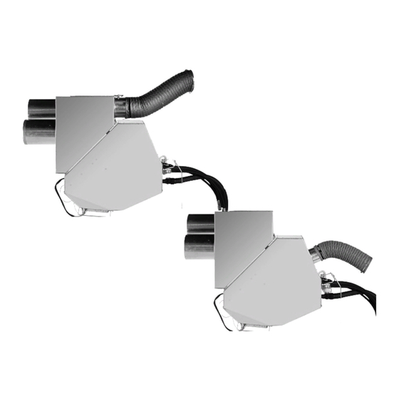
- Page 10 Figure titles and legends: “Electrical danger” Pictograph “Be careful with your hands” Pictograph “General Danger” Pictograph General overview of unit assembly Attachment rail Suspension box Air treatment module Attachment rail drawing, mm Attachment rail Suspension box and ATM assembly, mm False ceiling Partition for technical room Filter access door (open position)
-
Page 11: Precautions
Check whether the supply voltage and frequency correspond to environment. The levels of the chemical compounds below must those required for the unit to be installed. in no case be exceeded: CAUTION: Carrier suspends the effect of the warranty if these - SO < 0,02 ppm points are not followed, or if electrical changes have been <... -
Page 12: Safety Considerations
(GFCI circuit breaker not supplied by Carrier). Caution, the current leakage from the motor of the 2.1 - General points unit is 0.27 mA with operating voltage 230 V AC. -
Page 13: Installation Of The Unit
ATM. This fresh air flow can be adjusted using the box (blowing and recirculation of air). Ensure that the insides Carrier regulator (See 4.5.2 – Regulator for variable fresh air flow). of the ducts are clean to avoid the movement of construction debris which could damage the mechanical parts of the This box is provided with duct connection. -
Page 14: Procedure For Dismantling The Atm (Fig. 6)
3 - INSTALLATION OF THE UNIT 3.3 - Procedure for dismantling the ATM (Fig. 6) Cut the power supply to the apparatus, from the circuit breaker (not supplied by Carrier) provided for this purpose during installation. - Disconnect the electrical power supply cables. -
Page 15: Components
- Replace the fan motor and proceed with reassembly by CAUTION: The Carrier type B and D electronic thermostats applying the procedure in the reverse order. are provide with an 8 Amps electric battery relay. Carrier requires an additional protective relay for the electric coils 4.1.2 - Fan cabling above 1600 Watts. -
Page 16: Optional Air Filter And Access
CAUTION: Correctly follow the direction of flow of water indicated by an arrow on the valve body. This is connected to the Carrier digital regulator and can control the fresh air flow in two ways: 4.4 - Optional air filter and access - Either as a fixed flow by the installer and re-adjustable at will. -
Page 17: Optional Hydraulic Hose
4 - COMPONENTS 4.6.3 - Procedure for replacement of the valve bodies CAUTION: Before any intervention on this product, it is imperative to cut the electrical power supply of the unit. - Close the isolating valves located on the collectors. - Disconnect the hydraulic hoses on the ATM side by unscrewing the G 1/2’’... -
Page 18: Coding
5 - CODING Types of products Sizes Product reference Digits (1) Fixed values Digits 5/6 Digit 8 2 tubes 4 tubes 2 tubes/2 wires BP (PTC 2 cabled floors) 2 tubes/2 wires HP (PTC 5 cabled floors) 2 tubes/2 wires MP (PTC 4 cabled floors) Digit 16 Digit 9... - Page 20 Order No.: 14243, 07.2021 - replaces No.: 14243, 03.2014. Manufacturer: Carrier S.C.S Rte de Thil - 01120 Montluel - France. The manufacturer reserves the right to modify the product specifications without prior notice. Printed in the European Union.