Miele SmartLine Operating And Installation Instructions
Induction cooktop
Hide thumbs
Also See for SmartLine:
- Operating and installation instructions (84 pages) ,
- Operating and installation instructions (80 pages)
Table of Contents
Advertisement
Quick Links
Advertisement
Table of Contents

Related Manuals for Miele SmartLine


Summary of Contents for Miele SmartLine
- Page 1 Operating and installation instructions SmartLine induction cooktop To prevent the risk of accidents or damage to the appliance, it is essential to read these instructions before it is installed and used for the first time. en-AU, NZ M.-Nr. 10 878 120...
-
Page 2: Table Of Contents
Cooking zone data ....................18 Before using for the first time ................ 19 Cleaning the SmartLine appliance for the first time ..........19 Switching on the SmartLine appliance for the first time ........19 Induction ...................... 20 How it works......................20 Noises........................ - Page 3 Safety distances .................... 50 Installation notes .................... 52 Installation of surface-mounted appliances ............52 Flush-fit installation ....................53 Installing several SmartLine appliances ..............54 Combination with a downdraft extractor............... 54 Building-in dimensions .................. 55 Surface-mounted installation ................55 Flush-fit installation ....................56 Worktop cut-out for surface-mounted installation ..........
-
Page 4: Warning And Safety Instructions
They contain important notes on installation, safety, use and maintenance. Miele cannot be held liable for non-compliance with these instructions. Keep these instructions in a safe place and ensure that new users... - Page 5 This cooktop is not suitable for outdoor use. It is intended only to cook food and keep it warm. Any other use is not supported by Miele and could be dangerous. This cooktop is not intended for use by people (including children)
- Page 6 Warning and Safety instructions Safety with children Young children must not be allowed to use this appliance. Older children may use the appliance without supervision if its operation has been clearly explained to them and they are able to use it safely.
- Page 7 Unauthorised installation, maintenance and repairs can cause considerable danger for the user. Installation, maintenance and repairs must only be carried out by a Miele authorised technician. Damage to the cooktop can compromise your safety. Check the appliance for visible signs of damage. Do not use the cooktop if it is damaged.
- Page 8 The manufacturer's warranty will be invalidated if the appliance is not repaired by a Miele approved service technician. Faulty components must only be replaced by genuine Miele spare parts. The manufacturer can only guarantee the safety of the appliance when Miele replacement parts are used.
- Page 9 Warning and Safety instructions If the cooktop is installed behind a furniture door, do not close the door while the cooktop is in operation. Heat and moisture can build up behind the closed door. This can result in damage to the cooktop, the housing unit and the floor.
- Page 10 Warning and Safety instructions Correct use The cooktop gets hot when in use and remains hot for a while after being switched off. There is a danger of burning until the residual heat indicators go out. Oil and fat can overheat and catch fire. Do not leave the cooktop unattended when cooking with oil and fat.
- Page 11 Warning and Safety instructions When the appliance is switched on either deliberately or by mistake, or when there is residual heat present, there is the risk of any metal items left on the cooktop heating up, with the danger of burning.
- Page 12 Warning and Safety instructions Do not allow solid or liquid sugar, or pieces of plastic or aluminium foil to get onto the cooktop when it is hot, as they can damage the ceramic surface when it cools down. If this should occur, switch off the appliance and scrape off all the sugar, plastic or aluminium residues whilst still hot, using a shielded scraper blade suitable for use on glass.
- Page 13 Warning and Safety instructions Metal utensils stored in a drawer under the cooktop can become hot if the appliance is used intensively for a long time. Do not store any metal items or utensils in a drawer under the cooktop. ...
- Page 14 Warning and Safety instructions Cleaning and care Do not use a steam cleaning appliance to clean this appliance. The steam could reach the electrical components and cause a short circuit. If the cooktop is built in over a pyrolytic oven, the cooktop should not be used whilst the pyrolytic process is being carried out, as this could trigger the overheating protection mechanism on the cooktop (see relevant section).
-
Page 15: Caring For The Environment
Caring for the environment Disposal of the packing Disposing of your old material appliance The transport and protective packaging Electrical and electronic appliances has been selected from materials which often contain valuable materials. They are environmentally friendly for also contain specific materials, disposal, and can normally be recycled. -
Page 16: Overview
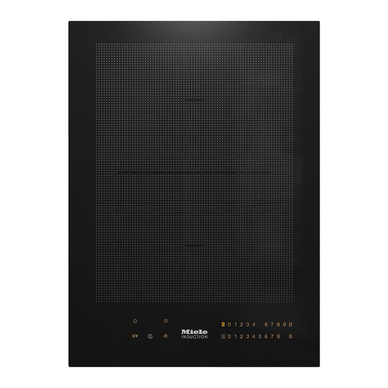
Overview Cooktop a PowerFlex cooking zone b PowerFlex cooking zone ab can be combined to form a PowerFlex cooking area c Controls / Indicators... -
Page 17: Controls / Indicators
Overview Controls / Indicators Sensor controls a For switching the cooktop on/off b Stop & Go c Wipe protection d Switching PowerFlex cooking zones on together/separately e Activating/Deactivating the keeping warm function f Numerical keybank For setting power levels/minute minder and switch-off times g Automatic switch-off selector for cooking zones h Minute minder Indicator lights... -
Page 18: Cooking Zone Data
Overview Cooking zone data Cooking zone Ø in cm* Rating in watts for 230 V** 15–23 Normal 2100 TwinBooster, level 1 3000 TwinBooster, level 2 3650 15–23 Normal 2100 TwinBooster, level 1 3000 TwinBooster, level 2 3650 + 22–23 / Normal 3150 15 x 23 – 23 x 39... -
Page 19: Before Using For The First Time
Alternatively, the additional some vapours may occur when the label can be stuck near the appliance SmartLine appliance is used for the first if the appliance markings are not time. The heating of the induction coils visible after installation. -
Page 20: Induction
Induction How it works When the appliance is switched on either deliberately or by mistake, An induction coil is located under each or when there is residual heat cooking zone. When a cooking zone is present, there is the risk of any metal switched on, this coil creates a items placed on the cooktop (e.g. -
Page 21: Noises
Induction Noises When using an induction cooking zone, the following noises can occur in the pan, depending on what it is made of and how it has been constructed. On the higher power levels, it might buzz. This will decrease or cease altogether when the power level is reduced. -
Page 22: Cookware
Induction – To make optimum use of the cooking Cookware zones, choose pans with a suitable Suitable pans include: base diameter (see “Cooking zones”). If the pan is too small, it will not be – stainless steel pans with a base that recognised and the set power level can be magnetised, will flash in the numerical keybank for... -
Page 23: Tips On Saving Energy
Tips on saving energy – Use a lid whenever possible to minimise heat loss. – Select a smaller pan when cooking small quantities. A smaller pan uses less energy than a larger pan with very little in it. – Cook with as little water as possible. –... -
Page 24: Power Level Range
Power level range The cooktop is programmed with 9 power levels at the factory. If you wish to fine- tune a setting, you can extend the power level range to 17 power levels (see “Programming”). Settings Default Extended setting settings (9 power (17 power levels) -
Page 25: Operation
Only the printed On/Off symbol is Keep the sensor controls and visible when the SmartLine appliance is indicators clean and do not place switched off. The other sensor controls anything on top of them. Do not light up when the SmartLine appliance place hot pans on them. -
Page 26: Switching On The Cooktop
Operation Switching off a cooking zone/ Fire hazard! the cooktop Do not leave the cooktop unattended whilst it is being used. To switch off a cooking zone, touch Please note that the heating up time the 0 sensor for that cooking zone. on induction cooktops is significantly ... -
Page 27: Setting The Power Level - Extended Power Level Range
Operation Setting the power level - PowerFlex area extended power level range The PowerFlex cooking zones combine automatically to form a PowerFlex Touch the numerical keybank in cooking area when you place a between two number sensors. sufficiently large pot or pan on them The sensors in front of and after the (see “Guide to the appliance - interim level will light up brighter than... -
Page 28: Auto Heat-Up
Operation Auto heat-up Continued Heat-up time cooking setting [min : sec] When Auto heat-up has been activated, the cooking zone switches on approx. 0 : 15 automatically at the highest setting and approx. 0 : 15 then switches to the continued cooking setting which you have previously approx. -
Page 29: Booster
Operation In each case two cooking zones are Booster linked together in order to provide The cooking zones are equipped with a sufficient power for the Booster. While TwinBooster. the Booster is in operation some of the power is taken away from the linked When activated, the power is boosted cooking zone. -
Page 30: Keeping Warm
Operation Activating/Deactivating the keeping Keeping warm warm function This function is for keeping food warm Touch the sensor for the cooking which has just been cooked and is still zone you wish to use. hot. It is not for reheating food that has gone cold. -
Page 31: Timer
Timer The SmartLine appliance has to be The functions can be used at the same switched on if you wish to use the timer. time. The shortest time is always A duration of between 1 minute (:) displayed and the sensor control and 9 hours 59 minutes (:) can be... -
Page 32: Switching Off A Cooking Zone Automatically
Timer Changing the switch-off time Switching off a cooking zone automatically Touch the sensor repeatedly until the indicator light for the zone you You can set a time after which the require flashes. cooking zone will switch off automatically. -
Page 33: Additional Functions
10 seconds. The minute minder, switch-off, Booster Switch the SmartLine appliance on and Auto heat-up times continue to run. again. When Stop & Go is deactivated, the cooking zones will operate at the power The previously set power levels flash. -
Page 34: Wipe Protection
SmartLine appliance can order, for example, to remove soiling. be displayed. To do this, there must not The sensor control is not locked. be any pots or pans on the SmartLine appliance. Activating Touch the sensor. -
Page 35: Safety Features
– A set minute minder time can be altered by mistake. modified. The system lock is activated when the – The SmartLine appliance can only be SmartLine appliance is switched off. If switched off. the system lock is activated, the... - Page 36 Safety features Activating the safety lock Touch and hold the and sensors at the same time for 6 seconds. The time counts down in the timer display. will appear once the time has elapsed. The safety lock is activated.
-
Page 37: Safety Switch-Off
Safety switch-off Power level* Maximum operating time [h:min] Safety switch-off if the sensors are Safety setting covered Your SmartLine appliance will turn off 10:00 8:00 5:00 automatically if one or several of the sensor controls remain covered for 10:00 7:00 4:00 longer than 10 seconds, for example,... -
Page 38: Overheating Protection
– The set power level will be reduced. If, despite removing the cause, the overheating protection mechanism – The cooking zone turns off triggers again, contact Miele. automatically. flashes alternately with in the timer display. You can use the cooking zone again as usual when the fault message has gone out. -
Page 39: Programming
Programming You can adapt the programming of the How to save the settings SmartLine appliance to your personal While the programme is visible in the needs. Several settings can be altered display (e.g. :), touch the in succession. sensor control until the indicators go out. - Page 40 Programming Settings Programme Code P:01 Demonstration mode C:00 Demonstration mode off C:01 Demonstration mode on P:03 Factory settings C:00 Factory default settings not restored C:01 Factory default settings restored P:04 Number of power levels C:00 9 power levels C:01 17 power levels P:06 Keypad tone when a sensor is C:00...
- Page 41 Programmes not shown here have no allocation. The factory setting is shown in bold. After the SmartLine appliance has been switched on, appears in the timer display for a few seconds. In the text and charts, the extended power levels are shown with a dot after the number for better understanding.
-
Page 42: Cleaning And Care
Allow the SmartLine appliance to Risk of burning on hot cooking cool down before cleaning. zones! The cooking zones will be hot after Clean the SmartLine appliance and use. accessories after each use. Switch the cooktop off. Dry the SmartLine appliance... - Page 43 Afterwards, clean the glass ceramic surface in its cooled state, as Then clean the ceramic glass surface described above. with the Miele ceramic and stainless steel cooktop cleaner (see “Optional accessories”) or with a proprietary ceramic glass cleaner applied with a paper towel or a clean cloth.
-
Page 44: Problem Solving Guide
With the help of the following guide, minor faults in the performance of the appliance, some of which may result from incorrect operation, can be remedied without contacting Miele. This will save you time and money because you will not need a service call. - Page 45 appears above the On/ Off sensor control . After the SmartLine The SmartLine appliance is in demonstration mode. appliance has been Touch the 0 and 2 sensor controls at the same switched on, appears time until flashes alternately with in the briefly in the timer timer display.
- Page 46 SmartLine appliance. Also ensure the area surrounding the SmartLine appliance is not too dark. Take any pans off the SmartLine appliance and wipe away any food deposits. Ensure that there is nothing covering the entire SmartLine appliance or sensor controls.
- Page 47 Possible cause and remedy 1 and a number, e.g. 1-0 Cooking zone fault flash alternately with a 3 Interrupt the power supply to the SmartLine digit number in the appliance for approx. 1 minute. timer display. If the problem persists after power is restored, please contact Miele.
-
Page 48: Optional Accessories
These products can be ordered from the Miele online shop. They can also be ordered directly from Removes heavy soiling, limescale Miele (see end of this booklet for deposits and aluminium residues. contact details). Original Miele all purpose microfibre cloth... -
Page 49: Safety Instructions For Installation
Safety instructions for installation Install the wall units and rangehood before installing the SmartLine appliance to avoid damaging it. The veneer or laminate coatings of worktops (or adjacent kitchen units) must be treated with 100 °C heat-resistant adhesive which will not dissolve or distort. -
Page 50: Safety Distances
For any flammable objects, e.g. utensil rails, wall units etc., a minimum safety distance of 600 mm must be maintained between these objects and the highest part of the SmartLine appliance below. When two or more SmartLine appliances which have different... - Page 51 The minimum distance specified appliance and an oven, interim shelf, or below must be observed between the drawer. rear of the SmartLine applianace and a tall unit or room wall. The minimum clearance from the lower edge of the SmartLine appliance to The minimum distance , ...
-
Page 52: Installation Notes
Grout lines and the hatched area underneath the SmartLine appliance frame must be smooth and even. If they are not, the SmartLine appliance will not sit flush with the worktop and the sealing strip underneath the top part of the appliance will not provide a good seal between the appliance and the worktop. -
Page 53: Flush-Fit Installation
(see “Worktop cut-out for flush-fit installation”), so that the SmartLine appliance is easily accessible from underneath after installation and the bottom half of the casing can be removed for maintenance. -
Page 54: Installing Several Smartline Appliances
Installation notes Installing several SmartLine appliances The gaps between the individual SmartLine appliances are sealed with a silicone sealant that is heat-resistant to at least 160 °C. With flush-fit installation, the gap between the SmartLine appliances and the worktop must also be sealed with a silicone sealant that is heat-resistant to at least 160 °C. -
Page 55: Building-In Dimensions
Building-in dimensions Surface-mounted installation a Front b Mains connection cable, L = 2000 mm... -
Page 56: Flush-Fit Installation
Building-in dimensions Flush-fit installation a Front b Mains connection cable, L = 2000 mm c Stepped cut-out (for detailed illustrations, see “Worktop cut-out for flush-fit installation”) d 12 mm wooden frame (not supplied, for detailed illustrations, see “Worktop cut- out for flush-fit installation”) -
Page 57: Worktop Cut-Out For Surface-Mounted Installation
1 appliance = width of the appliance minus 10 mm on the right, minus 10 mm on the left. Several SmartLine appliances = total width of the appliances plus 2 mm distance between the SmartLine appliances, minus 10 mm on the right, minus 10 mm on the left. - Page 58 Worktop cut-out for surface-mounted installation Installation with a downdraft extractor Sample combinations Number x width [mm] Dimension B Cooking Downdraft [mm] appliances extractor 1 X 378 1 X 120 2 X 378 1 X 120 1 x 378 2 X 120 1224 1 x 620 3 X 378 2 X 120 1362 2 x 378 2 X 120 1604 1 x 620 4 X 378 2 X 120 1742 1 X 620 2 X 120...
- Page 59 Worktop cut-out for surface-mounted installation Installation without a downdraft extractor Sample combinations Number x width [mm] Dimension B [mm] Cooking appliances 1 X 378 2 X 378 1 x 378 1 x 620 3 X 378 1118 2 x 378 1360 1 x 620 4 X 378 1498...
-
Page 60: Worktop Cut-Out For Flush-Fit Installation
When installing several SmartLine appliances, a distance of 2 mm must be observed between the individual SmartLine appliances. Calculating cut-out dimension A 1 SmartLine appliance = width of the appliances plus 2 mm on the right, plus 2 mm on the left. Several SmartLine appliances = total width of the appliances plus 2 mm distance between the SmartLine appliances, plus 2 mm on the right, plus 2 mm on the left. - Page 61 Worktop cut-out for flush-fit installation Installation with a downdraft extractor Sample combinations Number x width [mm] Dimension Dimension A B Cooking Downdraft [mm] [mm] appliances extractor 1 X 378 1 X 120 2 X 378 1 X 120 1 x 378 2 X 120 1248 1224 1 x 620 3 X 378 2 X 120 1386 1362 2 x 378 2 X 120 1628 1604 1 x 620 4 X 378...
- Page 62 Worktop cut-out for flush-fit installation Installation without a downdraft extractor Sample Number x width Dimension A Dimension B combinations [mm] [mm] [mm] Cooking appliances 1 X 378 2 X 378 1 x 378 1004 1 x 620 3 X 378 1142 1118 2 x 378 1384 1360 1 x 620 4 X 378 1522 1498...
-
Page 63: Spacer Bars
Spacer bars When installing several SmartLine appliances, an additional spacer bar must be fitted in between the individual appliances. The clips supplied with the spacer bars are only required for installing the CSDA 7000 FL. Installing 3 appliances and 2 spacer bars... -
Page 64: Installation
Fitting the spacer bars Create the worktop cut-out. Use the middle screw holes if one of the Remember to maintain the minimum following SmartLine appliances is safety distances (see “Safety installed to the right or left of the spacer distances”). -
Page 65: Installing The Smartline Appliances
Do not apply the sealing strip under tension. Feed the mains connection cable down through the cut-out. Position the SmartLine appliance in the worktop cut-out. When doing this, make sure that the seal of the appliance sits flush with the worktop on all sides. - Page 66 Installation Flush-fit installation Connect the SmartLine appliance to the mains electrical supply. Check that the SmartLine appliance works. Seal the gaps between the individual appliances and between the appliances and the worktop with a silicone sealant that is heat-resistant to at least 160 °C.
-
Page 67: Electrical Connection
Residual current device system (e.g. electric shock). For extra safety, it is advisable to The SmartLine appliance must be protect the SmartLine appliance with a connected to the mains electricity suitable residual current device (RCD) supply by a suitably qualified and with a trip range of 30 mA. - Page 68 When replacing the mains connection cable, it must be replaced with cable type H 05 V2V2-F with a suitable cross- section. These cables are available from Miele.
-
Page 69: Service
Service Contact in case of fault In the event of any faults which you cannot remedy yourself, please contact Miele. Contact information for Miele can be found at the end of this booklet. Please quote the model and serial number of your appliance when contacting Miele. - Page 71 Miele Experience Centre South Melbourne: Freemans Bay, Auckland 1011 206-210 Coventry Street South Melbourne, VIC 3205 Miele Experience Centre Auckland: Miele Experience Centre and Office Sydney: 8 College Hill 3 Skyline Place Freemans Bay, Auckland 1011 Frenchs Forest, NSW 2086 Telephone:...
- Page 72 CS 7612 en-AU, NZ M.-Nr. 10 878 120 / 02...