Dyson DC24 Service Manual
Hide thumbs
Also See for DC24:
- Operating manual (27 pages) ,
- Owner's manual (21 pages) ,
- Operation manual (20 pages)
Table of Contents
Advertisement
Advertisement
Table of Contents

Related Manuals for Dyson DC24


Summary of Contents for Dyson DC24
- Page 1 Service manual Issued Jan 08...
-
Page 3: Table Of Contents
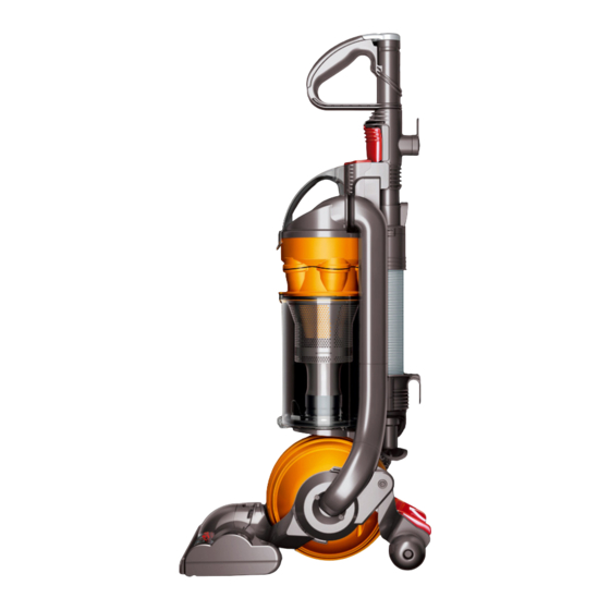
Service manual This manual is written specifically for Dyson trained engineers and covers the full DC24 range. The service instructions assume the engineer has the approved tools and test equipment with them. Contents Page Features Electrical safety testing Electrical circuit... - Page 4 Steers smoothly with a turn of the wrist. Washable lifetime HEPA filter Ultra-lightweight and compact HEPA filter is ideal for allergy sufferers. DC24 is our lightest upright machine. What’s more, the handle compresses so you can store it in small spaces.
-
Page 5: Electrical Safety Testing
These tests are vital to avoid any prior to and upon completion of all possibility of personal injury to the repairs to Dyson floorcare products and end user. before any functional checks. You must The Seaward Primetest 200 (or equivalent) -
Page 6: Electrical Circuit
Service manual Wiring Schematic Brushbar Main On/Off Switch Wire colours may vary between territories Switch Live Neutral Switch area COMPONENT TEST POINTS TERRITORY RESISTANCE (Ω) UK/Euro (230/240V) Vac motor 8.5 Approx 10 to 11 UK/Euro (230/240V) Cleaner head assembly 16 to 17 725 Approx Brushbar motor UK/Euro (230/240V) -
Page 7: Electrical Fault Diagnosis
Service manual Electrical fault diagnosis When DC24 is switched on in the upright position, the brushbar motor is off. Tilting the machine into normal vacuuming mode will automatically operate the upright switch, turning the brushbar motor on. The brushbar motor can be switched off using the brushbar switch. -
Page 8: General Notes
Wire colours may vary between territories. All screws used in DC24 are Torx T15 unless otherwise stated. DC24 contains a connector behind the upright switch cover. To disconnect any wires from it you will have to insert a fine bladed tool (1mm) to activate the release catch. - Page 9 Service manual 02 Remove the cleaner head assembly. 03 Remove the four screws from the ball assembly. 04 Remove the two halves of the ball assembly.
- Page 10 Service manual 05 Remove the post filter assembly. 06 If it needs replacing the post filter button can be prised out of the post filter assembly. 07 To fit, align the button onto the spring and push firmly into the retainers.
- Page 11 Service manual 08 If the post filter offering arm needs replacing carefully release the spring. 09 With the spring removed firmly push the post filter offering arm out of the housing on the motor bucket. Fit in reverse. 10 Remove the three long screws in the upright switch cover.
- Page 12 Service manual 11 Twist the upright switch cover off the side of the product. 12 Separate the internal cable connector. 13 Detach the wire from the lower terminal of the upright switch.
- Page 13 Service manual 14 Remove the long screw next to the arrow. 15 Firmly pull the lower duct hose off the side of the product. 16 Remove the long screw behind the lower duct hose.
- Page 14 Service manual 17 Release the yoke and motor assemblies from the duct assembly. Release catch 18 Release the yoke wire from the cable connector. 19 Remove the yoke assembly from the motor bucket.
- Page 15 Service manual 20 If the swivel lock needs replacing release the catch from the yoke assembly. 21 With the end released remove the swivel lock from the middle of the yoke assembly. 22 To fit, lower the swivel lock onto the detail on the middle of the yoke assembly.
- Page 16 Service manual 23 Ensure when fitting the swivel lock into the side of the yoke assembly that the spring locates onto the side of the peg. 24 If necessary the connector clip can be removed by initially inserting a screwdriver into the gap. 25 Once initially released it can then be removed by easing it away from the yoke assembly.
- Page 17 Service manual 26 To fit, ensure the yoke loom grommet is positioned in the connector clip as shown. 27 Ensure the yoke loom loops around the pip detail on the yoke. 28 Align the lugs on the connector clip with the detail on the yoke assembly.
- Page 18 Service manual 29 If replacing the motor remove the motor inlet seal. 30 Remove the bearings from either end of the motor bucket. 31 Remove the four screws in the motor bucket.
- Page 19 Service manual 32 Separate the two halves of the motor bucket. 33 Remove the motor cable assembly from the motor bucket front. 34 Remove the motor from the motor bucket rear assembly.
- Page 20 Service manual 35 Detach the motor wires from the motor cable assembly. 36 Remove the fancase seal and motor mount from the motor. 37 Remove the motor cable assembly from the fancase seal if necessary.
-
Page 21: Motor And Yoke Assembly Replacement - Fitting
Service manual Motor and yoke assembly replacement - fitting 38 Fit the motor mount onto the top of the motor. 39 Align the arrow detail on the fancase seal with the arrow printed on the side of the motor. 40 Fit the fancase seal ensuring the lip of it covers the fancase. - Page 22 Service manual 41 Ensure the fancase seal is seated centrally on the base of the motor. 42 If previously removed fit the wiring harness through the opening in the fancase seal. Connect the motor wires to the harness. 43 Dress the motor wires and harness neatly into the fancase seal.
- Page 23 Service manual 44 Feed the wiring harness through the opening in the motor bucket front. Pull the wiring harness grommet through the opening ensuring the notch detail catches. 45 Locate the motor bucket front into the fancase seal. 46 Lower the motor bucket rear assembly onto the motor.
- Page 24 Service manual 47 Ensure the motor bucket rear assembly is located within the detail on the fancase seal Fit the four screws. 48 Fit the bearings on the ends of the motor bucket. 49 Align the tabs on the connector clip with the slots in the end of the motor bucket.
- Page 25 Service manual 50 Ease the other end of the yoke assembly onto the lug on the motor bucket. 51 Locate the yoke wire into the cable connector. 52 Fit the motor inlet seal.
- Page 26 Service manual 53 Before fitting the yoke and motor bucket onto the duct ensure the internal cable wires are located into the channels on the duct. 54 Position the motor bucket and yoke onto the screws boss on the duct assembly. 55 Slide the other end into the duct ensuring the three holes align.
- Page 27 Service manual 56 Reconnect the two halves on the cable connector. Connect the red wire to the upright switch. Dress all wires neatly into the channels provided. 57 Fit the upright switch cover onto the side of the duct assembly. Fit the three long screws.
- Page 28 Service manual 59 Fit the post filter assembly. Fit the two halves of the ball assembly. Fit the four screws. 60 Locate the c-clip onto the top of the cleaner head assembly. 61 Align the pins on the cleaner head assembly with the plug on the yoke assembly.
-
Page 29: Stabiliser And Pedal Replacement - Removal
Service manual Stabiliser and pedal removal 62 Remove the three long screws in the upright switch cover. 63 Twist the upright switch cover off the side of the product. 64 Detach the two wires from the upright switch. Undo the short screw in the upright switch housing. - Page 30 Service manual 65 Carefully remove the upright switch housing. 66 If it needs replacing the upright switch can be carefully removed from the housing. 67 Remove the short screw and plastic washer.
- Page 31 Service manual 68 Remove the short screw and plastic washer from the other side of the duct. Remove the pedal assembly. 69 Remove the short screw and plastic washer holding the stabiliser assembly onto the duct assembly. 70 Prise the stabiliser over the large lug on the other side of the duct assembly.
- Page 32 Service manual 71 Using a pair of long nosed pliers unclip the stabiliser assembly from the spring.
-
Page 33: Stabiliser And Pedal Replacement-Fitting
Service manual Stabiliser and pedal replacement-fitting 72 Squeeze the spring firmly over the lug on the stabiliser assembly. 73 Locate the small lug on the stabiliser assembly into the hole in the side of the duct. Fit a plastic washer and short screw. - Page 34 Service manual 75 Slide the pedal axles into the channels in the stabiliser assembly. 76 Locate the lugs on the pedal into the holes on either side of the duct. Fit the plastic washers and short screws. 77 If previously removed ensure the upright switch and cam are positioned correctly on the upright switch housing.
- Page 35 Service manual 78 Carefully fit the upright switch housing onto the side of the duct assembly. Locate the cam spring into the channel on the duct. Fit the short screw. Attach the two red wires to the upright switch. 79 Fit the upright switch cover onto the side of the duct.
-
Page 36: Valve Wheel Replacement
Service manual Valve wheel replacement 80 Remove the cyclone and bin assemblies from the product. 81 Remove the Torx T-8 screw and washer. 82 Slide the centre of the valve wheel onto the lug on the end of the valve hatch and remove. Fit in reverse. -
Page 37: Valve Hose Replacement-Removal
Service manual Valve hose replacement-removal Before continuing the following parts should be removed as previously shown: Valve wheel (Page 33) 83 Release the top of the valve hose assembly from the side of the duct assembly. 84 Remove the rear retaining lug from the valve. -
Page 38: Valve Hose Replacement-Fitting
Service manual Valve hose replacement-fitting 86 Fit the seal ensuring the hole in the seal fits over the detail on the shuttle. 87 Lower the hose into the duct ensuring the pin on the shuttle locates into the channel. 88 Locate the retaining lugs on either side of the shuttle into the valve. - Page 39 Service manual 89 Push the hose onto the duct ensuring it is adequately seated. After fitting the previous parts the following parts should be fittied as previously shown: Valve wheel (Page 33)
-
Page 40: Valve Hatch Replacement-Removal
Service manual Valve hatch replacement-removal Before continuing the following parts should be removed as previously shown: Valve wheel (Page 33) Ball assembly (Page 6) 90 Remove the screw and captive washer from the hatch. 91 Carefully push the axle out of the valve hatch. - Page 41 Service manual 93 The valve seal can be removed if necessary.
-
Page 42: Valve Hatch Replacement-Fitting
Service manual Valve hatch replacement-fitting 94 If previously removed fit the valve hatch seal onto the valve. Ensure it is adequetly seated. 95 Fit the Valve hatch over the lugs on the valve. 96 Locate the legs of the spring into the channels on the hatch and valve. - Page 43 Service manual 97 Hold the axle in place to stop it from turning whilst fitting the screw and captive washer. After fitting the following parts should be replaced as previously shown: Valve wheel (Page 33) Ball assembly...
-
Page 44: Switch And Powercord Removal
Service manual Switch and powercord removal 98 Remove the wand assembly from the product. 99 Undo the three screws in the rear of the duct assembly. 100 Remove the switch cover from the front of the duct assembly. - Page 45 Service manual 101 Remove the switch buttons from the switch cover.* 102 If the locking slider or switch cover need replacing carefully remove the spring. 103 Prise the catch on the rear of the switch cover to remove the locking slider. Fit in reverse.
- Page 46 Service manual 104 Carefully detach the wires from the switches. 105 Prise the connection insulator out of the duct assembly. 106 Carefully open the connection insulator. Detach the neutral wires.
- Page 47 Service manual 107 Remove the powercord assembly from the duct.
-
Page 48: Switch And Powercord - Fitting
Service manual Switch and powercord - fitting 108 Feed the powercord assembly through the cable protector. Locate the end of the outer insulation into the channel as shown. 109 Locate the cable protector into the side of the duct assembly. 110 Attach the neutral wires together. - Page 49 Service manual 111 Locate the connection insulator over the neutral wires. 112 Route the neutral wire into the channel as shown. 113 Locate the connection insulator into the duct assembly.
- Page 50 Service manual 114 Attach a switch to the live wires from the powercord and internal powercord assemblies. 115 Locate the switch into the duct assembly. 116 Fit the other switch to the two remaining wires.
- Page 51 Service manual 117 Locate the second switch into the duct assembly. 118 If previously dismantled ensure the brushbar button, brushbar reset arm and spring are assembled as shown. 119 Lower the brushbar button into the switch cover.
- Page 52 Service manual 120 Lower the On/Off button and spring into the switch cover. Triangular detail Brushbar reset 121 Locate the switch cover onto the front of the duct assembly. Ensure when fitting that the brushbar reset arm locates into the triangular detail on the duct. Hold the switch cover in place and test the buttons.
- Page 53 Service manual 122 Pressing the On/Off button when the brushbar button is off should also activate the brushbar button. If this does not work check the position of the brushbar reset arm in the triangular detail. When working satisfactory fit the three screws.
-
Page 54: Duct Assembly Replacement - Dismantle
Service manual Duct assembly replacement - dismantle Before continuing the following parts should be removed as previously shown: Motor and yoke assembly (Pages 5 - 11) Stabiliser and pedal assembly (Pages 26- 29) Valve wheel (Page 33) Valve hose assembly (Page 34) Valve hatch assembly (Pages 37- 38) Switch and powercord assembly (Pages 41- 44) 123 The hose can be removed from... - Page 55 Service manual 125 The combination tool clip can also be removed at any stage by undoing the screw in the centre of it. 126 And sliding it off the side of the duct. Fit in reverse. 127 Undo the two screws shown.
- Page 56 Service manual 128 Followed by the screw on the underside of the duct. 129 With the screws removed slide the upright lock assembly off the side of the duct. 130 Should it need replacing the pedal plunger can be replaced by carefully detaching the spring and removing the plunger.
- Page 57 Service manual 131 Undo the three screws in the underside of the duct assembly. 132 Remove the valve U-bend from the duct assembly. 133 Remove the entry seal from the duct assembly.
- Page 58 Service manual 134 Remove the exhaust seal from the duct assembly. 135 Remove the internal powercord assembly from the duct assembly.
-
Page 59: Duct Assembly Replacement - Fitting
Service manual Duct assembly replacement - fitting 136 Slide the end of the outer insulation of the internal powercord under the retainer in the base of the duct assembly. 137 Push the end of the insulation into the channel. 138 Feed the switch end of the internal powercord through the window in the duct assembly. - Page 60 Service manual 139 Locate the internal powercord under all the retainers along the length of the duct assembly. 140 Fit the exhaust seal. 141 Fit the entry seal.
- Page 61 Service manual 142 Locate the valve U-bend onto the base of the duct assembly. Fit the three screws. 143 Before fitting the upright lock assembly ensure the pedal spring is located in the orientation shown. 144 Slide the upright lock assembly onto the valve U-bend.
- Page 62 Service manual 145 Locate the hose onto the rear of the duct assembly. After fitting, the following parts should be fitted as previously shown: Motor and yoke assembly (Pages 23 - 25) Stabiliser and pedal assembly (Pages 30 - 32) Valve hose assembly (Pages 35 - 36) Valve hatch assembly (Pages 39 - 40) Valve wheel (Page 33)
-
Page 63: Sub Assemblies-Wand Handle Assembly
Service manual Sub assemblies-Wand handle assembly 146 Should it need replacing the wand cap can be prised off the top of the wand assembly. Fit in reverse. -
Page 64: Sub Assemblies-Cyclone Assembly
Service manual Sub assemblies-cyclone assembly 147 Any parts that make up the bleed valve can be replaced by unlocking the bleed valve cap assembly. 148 With the bleed valve cap unlocked, prise it away from the cyclone cap assembly. Remove all parts of the bleed valve from the cyclone cap assembly. - Page 65 Service manual 150 The bin seal can be replaced. When fitting a new one ensure the detail on the seal aligns with the notch on the cyclone assembly. 151 If the FDC seal needs replacing ensure the new one covers all the ribs on the dust collector.
-
Page 66: Sub Assemblies-Bin Assembly
Service manual Sub assemblies-bin assembly 152 The bin catch can be replaced by prising off from the lugs on the bin. 153 To fit, press firmly onto the lugs ensuring the spring locates onto the retainers. 154 The bin base assembly can be firmly prised off the base of the bin. - Page 67 Service manual 155 If replacing the bin base seal ensure the new one is fitted adequately around all edges of the bin base. 156 Firmly press the new bin base assembly onto the lugs on the bin.
-
Page 68: Sub Assemblies-Cleaner Head Assembly
Service manual Sub assemblies-cleaner head assembly 157 The soleplate wheels or axles can be removed by prising out of the soleplate. To fit firmly push into place. 158 If the flicker strip needs replacing lift the end out of the soleplate using a thin flat bladed screwdriver. - Page 69 Service manual 160 To fit, slide along the length of the soleplate under the retainers. Press the end under the last retainer. 161 If the PCB need replacing, remove the flicker strip and nine Torx T-10 screws (eight in Japanese models). 162 With the screws removed, lift the brushbar motor cover off the cleaner head.
- Page 70 Service manual 163 Carefully detach all wires from the board. 164 Release the PCB assembly from under the retaining catch.
- Page 71 Service manual 165 To fit locate the front of the new PCB assembly under the brush housing and lower under the retaining catch. 166 Reconnect all wires to the PCB assembly. 167 Lower the brushbar motor cover onto the cleaner head assembly. Fit the nine screws and flicker strip.
-
Page 72: Main Body
Service manual Main body Entry Seal Brushbar Reset Arm Exhaust Seal Spring Connection Insulator On/Off Button Combination Tool Clip Brushbar Button Valve Hose Assy Spring Shuttle Seal Switch Screw Switch Duct Assy Cover Internal Powercord Assy Locking Slider Cable Protector Spring Valve Wheel Powercord Assy... -
Page 73: Motor Assembly
Service manual motor assembly Small Bearing Post Filter Assy Post Filter Button Spring Post Filter Offering Arm Spring Post Filter Door Assy Ball Assy Motor Assy Motor Cable Assy Fancase Seal YDK Rear Motor Bucket Assy Motor Mount Screw Swivel Lock Spring Screw/Captive Washer Yoke Bracket... -
Page 74: Cyclone And Bin Assemblies
Service manual Cyclone and bin assemblies Bleed Valve Housing Bleed Valve Housing Seal Bleed Valve Cap Seal Bleed Valve Cyclone Cap Assy Spring Pre-Filter Assy Cyclone Assy Bin Seal FDC Seal Spring Bin Catch Bin Assy Bin Base Seal Bin Base Assy... -
Page 75: Cleaner Head Assembly
Service manual Cleaner head assembly PCB Assy End Cap Assy C-Clip Bumper Strip Cleanerhead Flicker Strip Assy Brushbar Assy Soleplate Wheel Axle Screw... -
Page 76: Wand And Hose Assemblies
Service manual Wand and hose assemblies Wand Cap Instruction Pack Wand Assy Combination Tool Assy Swivel Catch Spring Hose Assy...