Table of Contents
Advertisement
Quick Links
Advertisement
Table of Contents

Related Manuals for York CIW01


Summary of Contents for York CIW01
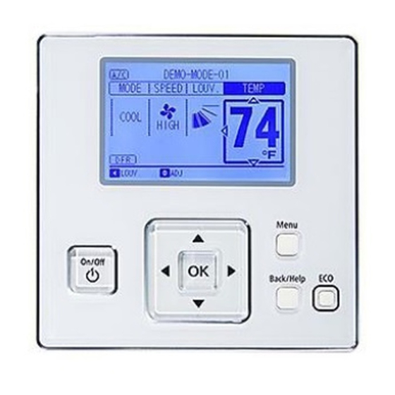
- Page 1 Installation & Maintenance Manual Wired Controller FLTR Meeting Room MODE SPEED LOUV. TEMP Model: CIW01 COOL LOUV. Adj. Menu On/Off Back/Help ECO IMPORTANT: READ AND UNDERSTAND THIS MANUAL BEFORE USING THIS WIRED CONTROLLER. KEEP THIS MANUAL FOR FUTURE REFERENCE. P5415484...
-
Page 2: Table Of Contents
Important Notice ● Johnson Controls Inc. pursues a policy of continuing improvement in design and performance in its products. As such, Johnson Controls Inc. reserves the right to make changes at any time without prior notice. ● Johnson Controls Inc. cannot anticipate every possible circumstance that might involve a potential hazard. ●... -
Page 3: Safety Summary
1. Safety Summary Signal Words Indicates a hazardous situation that, if not avoided, could result in death or serious injury. Indicates a hazardous situation that, if not avoided, could result in minor or moderate injury. Indicates information considered important, but not hazard-related (for example, messages relating to property damage). - Page 4 ● During the test run, check the unit’s operation temperature. If the unit is used in an environment where the temperature exceeds the operation boundary, it may cause severe damage. Check the operation temperature boundary in the manual. If there is no specifi ed temperature, use the unit within the operation temperature boundary of 35°...
- Page 5 ● Do not clean with, or pour water into, the controller as it could cause electric shock and/or damage the unit. Do not use strong detergent such as a solvent. Clean with a soft cloth. ● Verify that the ground wire is securely connected. Do not connect ground wiring to gas piping, water piping, lighting conductor, or telephone ground wiring.
-
Page 6: Brand Label
2. Brand Label Select the accessory brand label according to the production order. Attach the accessory brand logo label to this area. Menu On/Off Back/Help ECO This Area The box is to verify your work. Each task to verify that it has been done. 3. - Page 7 2. Attach the controller to the holding bracket and connect the cable as follows. A. In Case of Exposing the Controller Cable Trace-out Hole Cable Attach the stopper (plastic band) Band Stopper to the cable at the inside of (Field-Supplied) the draw-out hole.
-
Page 8: Electrical Wiring
Refer to the “Language 2. There was an incorrect connection issue regarding may be activated. Setting” of the CIW01’s interconnecting cables between indoor units or of the operation manual for details. Cancel “Test Run” mode controller cable. -
Page 9: Function Selection And Input/Output Setting From The Controller
6. Function Selection and Input/Output Setting from the Controller • Setting from Test Run Menu Press and hold “Menu” and “Back/Help” simultaneously Test Run Menu for at least 3 seconds during the normal mode (when unit Test Run is not operated). The Test Run menu is displayed. Function Selection Thermistor Selection Select “Function Selection”... - Page 10 ● Table A: Optional Setting Items for Function Selection Individual Setting Items Optional Function Contents Setting Setting Condition Standard (Set Temp. +7 F (+4 C)) (*1) Cancellation of Heating Removal (Set Temp.) ○ Temperature Compensation Set Temp. +3 F (+2 C) (*2) due to Uneven Heat Load Set Temp.
- Page 11 Individual Setting Items Optional Function Contents Setting Setting Condition < Wall Mounted Type > Standard (7-Step Operation) (5 steps for cooling / dry mode) Cold Draft Prevention (5 Steps: lower 2 steps cut off) (Heating and fan only) ○ Change of Louver Swing Angle Not Used <...
- Page 12 Individual Setting Items Optional Function Contents Setting Setting Condition Wired Controller Primary-Secondary Primary × Setting Secondary Automatic Reset of Setting Not Available × Temperature (*5) Available 30 min. (Factory-Setting) 15 min. × Automatic Reset Time 60 min. 90 min. 66 (19) F (19 68 (20) F (20...
- Page 13 Individual Setting Items Optional Function Contents Setting Setting Condition F (30 F (29 F (28 F (27 F (26 F (25 Heating Upper Limit for Setting × F (24 Temperature (*7) F (23 F (22 F (21 F (20 F (19 F (18 Not Prepared Not Used (Use as 00 setting conditions)
- Page 14 Individual Setting Items Optional Function Contents Setting Setting Condition Operation Setting during COOL/DRY ○ Thermistor of Wired Controller HEAT or Remote Sensor Normal Radiation Temperature Sensor Upper ○ Calibration Lower Normal Control of Dew Condensation Not Available ○ Prevention Available (Only for Mini Cassette Type) (*10) Not Prepared Not Used (Use as 00 setting conditions)
- Page 15 Individual Setting Items Optional Function Contents Setting Setting Condition -3(-1.5) F (-1.5 -4(-2.5) F (-2.5 -5(-3.0) F (-3.0 -6(-3.5) F (-3.5 × Auxiliary Heater ON Compensation -7(-4.0) F (-4.0 -8(-4.5) F (-4.5 -9(-5.0) F (-5.0 -1(-0.5) F (-0.5 -2(-1.0) F (-1.0 0(0.0) F (0.0 ×...
- Page 16 Individual Setting Items Optional Function Contents Setting Setting Condition 2(1.0) F (1.0 3(1.5) F (1.5 Cooling/Heating Changeover × 4(2.5) F (2.5 Temperature 5(3.0) F (3.0 1(0.5) F (0.5 4(2.5) F (2.5 5(3.0) F (3.0 6(3.5) F (3.5 7(4.0) F (4.0 8(4.5) F (4.5 ×...
- Page 17 Individual Setting Items Optional Function Contents Setting Setting Condition Not Available 68°F (20.0°C) 70°F (21.0°C) 72°F (22.0°C) 74°F (23.0°C) 75°F (24.0°C) 77°F (25.0°C) 78°F (26.0°C) 80°F (27.0°C) 82°F (28.0°C) 84°F (29.0°C) 86°F (30.0°C) 88°F (31.0°C) 90°F (32.0°C) 92°F (33.0°C) 94°F (34.0°C) 95°F (35.0°C) 96°F (36.0°C) 99°F (37.0°C)
- Page 18 Individual Setting Items Optional Function Contents Setting Setting Condition Not Available 50°F ( 10.0°C) 52°F ( 11.0°C) 54°F ( 12.0°C) 56°F ( 13.0°C) 58°F ( 14.0°C) 59°F ( 15.0°C) 60°F ( 16.0°C) 62°F ( 17.0°C) 64°F ( 18.0°C) 66°F ( 19.0°C) 68°F ( 20.0°C) 70°F ( 21.0°C) 72°F ( 22.0°C)
- Page 19 Individual Setting Items Optional Function Contents Setting Setting Condition 59°F (15.0°C) 60°F (16.0°C) 62°F (17.0°C) 64°F (18.0°C) Setback Activating Temp. 66°F (19.0°C) × for Heat Mode 50°F (10.0°C) 52°F (11.0°C) 54°F (12.0°C) 56°F (13.0°C) 58°F (14.0°C) 78°F (26.0°C) 80°F (27.0°C) 82°F (28.0°C) 84°F (29.0°C) 86°F (30.0°C)
- Page 20 (*1): Temperatures for Floor Exposed Type & Floor Concealed Types are not offset. Setting temperature are used as they are. (*2): The “02”, “03”, “04” settings may not be available depending on the type of indoor unit. When connecting multiple indoor units, do separate settings. (*3): If Duct type models, 00: Increasing fan speed 1 (standard), 01: Increasing fan speed 2 (high static pressure), 02: Standard (low static pressure).
-
Page 21: Individual Louver Setting
7. Individual Louver Setting This setting is available only for an indoor unit equipped with just an individual louver. Each louver angle can be set individually as shown in the following procedure. Press and hold “Menu” while in the normal mode (when the unit is in operation). -
Page 22: Adjusting Date/Time
8. Adjusting Date/Time The date and time can be set from “Adjusting Date/Time”. Press “Menu” while in the normal mode. The menu is displayed. 2. Select “Adjusting Date/Time” from the menu and press “OK”. Press “ ” and select “yyyy/mm/dd/hh/mm”. Adjusting Date/Time yyyy mm dd hh mm... -
Page 23: Setting Of Main Controller
10. Setting of Main Controller In the example system shown below, the Main and Sub wired controllers are confi gured automatically along with a corresponding icon on the display. If opting to change over from "SUB" to "MAIN" controller, follow the steps below: A visual example of a refrigeration environment containing a group of multiple controllers: The indoor and outdoor units need to correspond with the functions shown in table D. -
Page 24: Main/Sub Non-Display Setting
● When using two controllers, only the primary controller can be set as the main controller. In cases where two controllers are both sub controllers, the “Main Remote Control Setting” is only accessible from the master controller. ● In cases where the primary controller is a "Main Controller" and the secondary controller is a "Sub Controller", when the primary controller and the secondary controller are changed by the function selection, Main and Sub controllers is also switched simultaneously. -
Page 25: Setback Trigger Unit
12. Setback Trigger Unit This function is used to change trigger unit. In normal mode (while air conditioner is NOT set to ON), press “Menu” switch and “Back/Help” switch simultaneously for 3 seconds or longer. Test Run menu is shown. Select “Setback Trigger Unit”... -
Page 26: Operation Mode/Setting Temperature Priority Setting
13. Operation Mode / Setting Temperature Priority Setting It is feasible only to set the operation mode and unit temperature setpoint, from one specifi c controller (the main controller) in the same refrigerant system without having to use the central station. The sub controller acts in accordance with the settings of the main controller which is effective management of temperature depending on the interval of the priority operation mode and power saving settings. -
Page 27: Contact Information Registration
14. Contact Information Registration Contact information can be registered from the Contact Information screen. Press and hold “Menu” and “Back/Help” simultaneously for at least 3 seconds during the normal mode (when unit is not in operation). The Test Run menu is displayed. Select “Contact Information”... - Page 28 © 2017 Johnson Controls, Inc. P5415484-rev.4 , 2019 LIT-12013122 Issued September, 2019...