Table of Contents
Advertisement
Quick Links
- 1 Installation Work
- 2 Electrical Wiring
- 3 Checking Procedures
- 4 Function Selection and Input/Output Setting from the Controller
- 5 Input and Output Settings and Display Codes
- 6 Setting of Main Controller
- 7 To Toggle from the Sub Controller to the Main Controller
- 8 Operation Mode / Setting Temperature Priority Setting
- Download this manual
Advertisement
Table of Contents

Related Manuals for York CIW01


Summary of Contents for York CIW01
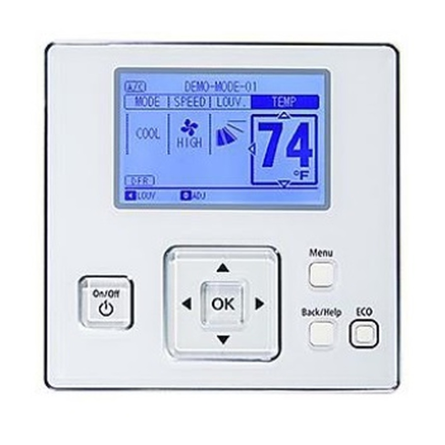
- Page 1 Installation & Maintenance Manual Wired Controller FLTR Meeting Room MODE SPEED LOUV. TEMP - CIW01 - COOL LOUV. Adj. Menu On/Off Back/Help ECO IMPORTANT: READ AND UNDERSTAND THIS MANUAL BEFORE USING THIS WIRED CONTROLLER. KEEP THIS MANUAL FOR FUTURE REFERENCE.
- Page 2 Liability does not cover defects originating from unauthorized modifi cations performed by a customer without the written consent of Johnson Controls, Inc. and York. Performing any mechanical alterations on this product without the consent of the manufacturer will render your warranty null and void.
- Page 3 ● When transporting, be careful when picking up, moving and mounting these units. Although the controller may be packed using plastic straps, do not use them for transporting from one location to another. Do not stand on or put any material on the controller. ●...
- Page 4 Electrical Precautions Take the following precautions to reduce the risk of electric shock, fi re or explosion resulting in serious injury or death: ● Only use electrical protection equipment and tools suited for this installation. ● Insulate the wired controller against moisture and temperature extremes. ●...
- Page 5 2. Brand Label Select the accessory brand label according to the production order. (HITACHI or YORK) Attach the accessory brand logo label to this area. Menu On/Off Back/Help ECO This Area The box is to verify your work. Check-off each task to verify that it has been done.
- Page 6 2. Attach the controller to the holding bracket and connect the cable as follows. A. In Case of Exposing the Controller Cable Trace-out Hole Cable Attach the stopper (plastic band) Band Stopper to the cable at the inside of (Field-Supplied) the draw-out hole.
- Page 7 Refer to the “Language 2. There was an incorrect connection issue regarding may be activated. Setting” of the CIW01’s interconnecting cables between indoor units or of the operation manual for details. Cancel “Test Run” mode controller cable.
- Page 8 6. Function Selection and Input/Output Setting from the Controller • Setting from Test Run Menu Press and hold “Menu” and “Back/Help” simultaneously Test Run Menu for at least three seconds during the normal mode Test Run (when unit is not operated). The Test Run menu will be displayed.
- Page 9 ● Table A: Optional Setting Items for Function Selection Individual Setting Items Optional Function Contents Setting Setting Condition Standard (Set Temp. +7 F (+4 Cancellation of Heating Removal (Set Temp.) ○ Temperature Compensation Set Temp. +3 F (+2 C) (*1) due to Uneven Heat Load Set Temp.
- Page 10 Individual Setting Items Optional Function Contents Setting Setting Condition Standard (7-Step Operation) Cold Draft Prevention ○ Change of Louver Swing Angle (5 Steps: lower 2 steps cut off) High Ceiling (higher 2 steps cut off) Not Available ○ Power Supply ON/OFF 1 Available Not Prepared Not Used...
- Page 11 Individual Setting Items Optional Function Contents Setting Setting Condition 66 (19) F (19 68 (20) F (20 70 (21) F (21 72 (22) F (22 74 (23) F (23 Automatic Reset Temperature 76 (24) F (24 × for Cooling (*4) 77 (25) F (25 C) (Factory-Setting)
- Page 12 Individual Setting Items Optional Function Contents Setting Setting Condition Show × No Indication of Auto Control Not Show Not Prepared Not Used (Use as 00 conditions) Not Prepared Not Used (Use as 00 conditions) Not Prepared Not Used (Use as 00 conditions) Not Prepared Not Used Green...
- Page 13 Individual Setting Items Optional Function Contents Setting Setting Condition Not Prepared Not Used (Use as 00 conditions) Inlet Air Thermistor Outlet Air Thermistor × Thermistor Selection Thermistor of Wired Controller Remote Sensor Not Available × Display of Thermistor Temperature Available Dispalyed ×...
- Page 14 Individual Setting Items Optional Function Contents Setting Setting Condition 4(2.5) F (2.5 5(3.0) F (3.0 6(3.5) F (3.5 7(4.0) F (4.0 8(4.5) F (4.5 × Setback Temperature Compensation 9(5.0) F (5.0 10(5.5) F (5.5 1(0.5) F (0.5 2(1.0) F (1.0 3(1.5) F (1.5 Not Prepared...
- Page 15 ● Table B: Input and Output Number Display and Connectors Input Number Display Factory Setting Port Setting Input/Output Indication Setting Item Indication Input 1 CN3 1-2 Remote ON/OFF 1 (Level) Input 2 CN3 2-3 Prohibiting Remote Control after Manual Stoppage Output 1 CN7 1-2 Operation...
- Page 16 7. Individual Louver Setting This setting is available only for an indoor unit equipped with just an individual louver. Each louver angle can be set individually as shown in the following procedure. Press and hold “Menu” while in the normal mode (when the unit is in operation).
- Page 17 8. Adjusting Date/Time The date and time can be set from “Adjusting Date/Time”. Press “Menu” while in the normal mode. Menu 15:10(Fri) The menu will be displayed. Adjusting Date/Time Daylight Saving Time Screen Display Setting 2. Select “Adjusting Date/Time” from the menu and Function 19 press “OK”.
- Page 18 10. Setting of Main Controller In case of the System Constitution below, the Main or Sub Remote Control will be set automatically, after being fi xed and an icon will be displayed. If opting to change over from "SUB" to "MAIN" controller, follow the steps below: A visual example of a refrigeration environment containing a group of multiple controllers: The indoor and outdoor units need to correspond with the functions shown in table D.
- Page 19 ● When using two controllers, only the primary controller can be set as the main controller. In cases where two controllers are both sub controllers, the “Main Remote Control Setting” is only accessible from the master controller. ● In cases where the primary controller is a "Main Controller" and the secondary controller is a "Sub Controller", when the primary controller and the secondary controller are changed by the function selection, Main and Sub controllers will also be switched simultaneously.
- Page 20 12. Operation Mode / Setting Temperature Priority Setting It is feasible only to set the operation mode and unit temperature setpoint, from one specifi c controller (the main controller) in the same refrigerant system without having to use the central station. The sub controller will act in accordance with the settings of the main controller which is effective management of temperature depending on the interval of the priority operation mode and power saving settings.
- Page 21 13. Contact Information Registration Contact information can be registered from the Contact Information screen. Press and hold “Menu” and “Back/Help” simultaneously for at least three seconds during the normal mode (when unit is not in operation). The Test Run menu will be displayed. Select “Contact Information”...
- Page 22 P5415484...
- Page 23 P5415484...
- Page 24 © 2017 Johnson Controls, Inc. P5415484-rev.2 , 2017...