Table of Contents
Advertisement
Quick Links
Advertisement
Table of Contents

Related Manuals for Elation SIXPAR 100IP


Summary of Contents for Elation SIXPAR 100IP
- Page 1 SIXPAR 100IP™ user manual...
- Page 2 Elation Professional B.V. | Junostraat 2 | 6468 EW Kerkrade, The Netherlands +31 45 546 85 66 | +31 45 546 85 96 fax | www.elationlighting.eu | info@elationlighting.eu Elation Professional Mexico | AV Santa Ana 30 | Parque Industrial Lerma, Lerma, Mexico 52000 +52 (728) 282-7070...
-
Page 3: Table Of Contents
C O N T E N T S General Information Limited Warranty (USA Only) Safety Guidelines Overview Installation DMX Setup System Menu Dimmer Mode DMX Channel Functions and Values Maintenance Guidelines Specifications Optional Accessories... -
Page 4: General Information
Female 5pin XLR to IP Male DMX Output Cable 3.3 ft (1m) Manual & Warranty Card CUSTOMER SUPPORT Contact ELATION Service for any product related service and support needs. Also visit forums.elationlighting.com with questions, comments or suggestions. ELATION SERVICE USA - Monday - Friday 8:00am to 4:30pm PST 323-582-3322 | Fax 323-832-9142 | support@elationlighting.com... -
Page 5: Limited Warranty (Usa Only)
B. For warranty service, send the product only to the Elation Professional factory. All shipping charges must be pre-paid. If the requested repairs or service (including parts replacement) are within the terms of this warranty, Elation Professional will pay return shipping charges only to a designated point within the United States. -
Page 6: Safety Guidelines
This fixture is a sophisticated piece of electronic equipment. To guarantee a smooth operation, it is important to follow all instructions and guidelines in this manual. Elation Professional is not responsible for injury and/or damages resulting from the misuse of this fixture due to the disregard of the information printed in this manual. - Page 7 S A F E T Y G U I D E L I N E S RISK GROUP 3 - RISK OF EXPOSURE TO ULTRAVIOLET UV RADIATION! FIXTURE EMITS HIGH INTENSITY WAVELENGTH OF ULTRAVIOLET UV LIGHT FROM THE UV LED. WEAR PROPER EYE AND SKIN PROTECTION.
-
Page 8: Overview
O V E R V I E W System Menu LCD & Controls Mounting Brackets/Yokes Valve Power Out “S” Knobs to tighten DMX OUT Brackets/Yokes Lens POWER IN DMX IN... - Page 9 * lbf-in = Pound Force Inches | kgf-cm = Kilogram Force Centimeters CAUTION! DO NOT OVER TORQUE SCREWS AS THIS CAN CAUSE LEAKAGE ISSUES! TO CONFIRM THE IP65 INTEGRITY AFTER A LAMP REPLACEMENT, TEST FIXTURE USING THE ELATION IP TESTER. CONTACT ELATION SERVICE FOR MORE DETAILS.
-
Page 10: Installation
I N S TA L L AT I O N G U I D E L I N E S FLAMMABLE MATERIAL WARNING Keep fixture minimum 5.0 feet (1.5m) away from flammable materials and/or pyrotechnics. ELECTRICAL CONNECTIONS A qualified electrician should be used for all electrical connections and/or installations. USE CAUTION WHEN POWER LINKING OTHER MODEL FIXTURES AS THE POWER CONSUMPTION OF OTHER MODEL FIXTURES MAY EXCEED THE MAX POWER OUTPUT ON THIS FIXTURE. - Page 11 I N S TA L L AT I O N G U I D E L I N E S MOUNTING THE FIXTURE ON A TRUSS USING CLAMP When mounting the fixture to a truss, be sure to secure an appropriately rated professional grade rigging clamp (not included) to the closed dual yokes using an M10 screw fitted through the center hole of the closed dual yokes.
- Page 12 I N S TA L L AT I O N G U I D E L I N E S RIGGING Overhead rigging requires extensive experience, including among others calculating working load limits, installation material being used, and periodic safety inspection of all installation material and the fixture.
-
Page 13: Dmx Setup
Connect the provided XLR cable to the female XLR output of your controller and the other side to the male XLR input of the SIXPAR 100IP™ . The diagram below illustrates a typical DMX-512 connection when the fixture is in the 12 Channel Mode. You can chain multiple panels together through serial linking. - Page 14 That means changing the settings of one channel will only affect the selected fixture. In the case of the SIXPAR 100IP™, when in the 12 Channel Mode you should set the starting DMX address of the first unit to 1, the second unit to 13 (1 + 12), the third unit to 25 (13 + 12), and so on.
-
Page 15: System Menu
The (4) button control panel (see image below) located on back of the fixture allows you to access the main menu and make all necessary adjustments to the SIXPAR 100IP™. During normal operation, pressing the MODE button will navigate through the different function menus. - Page 16 S YS T E M M E N U ELATION SIXPAR 100IP Supports Software Versions: ≥ 1.3 OPTIONS / VALUES MAIN MENU DESCRIPTION (Default Settings in BOLD) Channel CH: 06, 07, 08, 12 DMX Channel Mode DMX Mode ADDR: 001 ~ 512...
-
Page 17: Dimmer Mode
D I M M E R M O D E... -
Page 18: Dmx Channel Functions And Values
D M X T R A I T S : C H A N N E L F U N C T I O N S & VA L U E S ELATION SIXPAR 100IP DMX Channel Values / Functions Supports Software Versions: ≥... - Page 19 ELATION SIXPAR 100IP DMX Channel Values / Functions Supports Software Versions: ≥ 1.0 Features subject to change without notice MODE/CHANNEL VALUE FUNCTION 12CH 116-119 RED + WHITE + AMBER 120-123 RED + WHITE + UV 124-127 RED + AMBER + UV...
-
Page 20: Maintenance Guidelines
Regular inspections are recommended to insure proper function and extended life. There are no user serviceable parts inside this fixture, please refer all other service issues to an authorized Elation service technician. Should you need any spare parts, please order genuine parts from an authorized Elation dealer. -
Page 21: Specifications
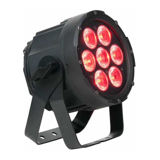
S P E C I F I C AT I O N S SOURCE (7) 12W 6-in-1 RGBAW+UV LEDs 100,000 Hour Average LED Life* *LED Life may vary depending on several factors including but not limited to: Environmental Conditions, Power/Voltage, Usage Patterns (On-Off Cycling), Control, and Dimming. - Page 22 P H O T O M E T R I C D ATA D I M E N S I O N S *Drawings not to scale. Specifications and improvements in the design of this unit and this manual are subject to change without notice.
-
Page 23: Optional Accessories
O P T I O N A L A C C E S S O R I E S ORDER CODE ITEM SIXPAR100/GFH Gel Frame Holder Kit SIXPAR/BD100 Barn Door NOTE: Gel Frame Holder Kit required to attach Barn Door. (Sold separately) SIXPAR/2MDLC 6.6 ft.