
Related Manuals for Panasonic B01


Summary of Contents for Panasonic B01
- Page 1 High Current Connectors B01 / B02 Operation manual ACCTF34E 2017.10 industrial.panasonic.com/ac/e/...
- Page 2 Operation manual for “High Current connectors B01/B02” Contents 01.Introduction ..................... 2 02.Precautions for product design ............... 3 03.Precautions for mounting and reflow soldering ........13 04.Precautions for mating and unmating ........... 20 Points which particularly need to be confirmed before designing products are bold and underlined.
-
Page 3: Introduction
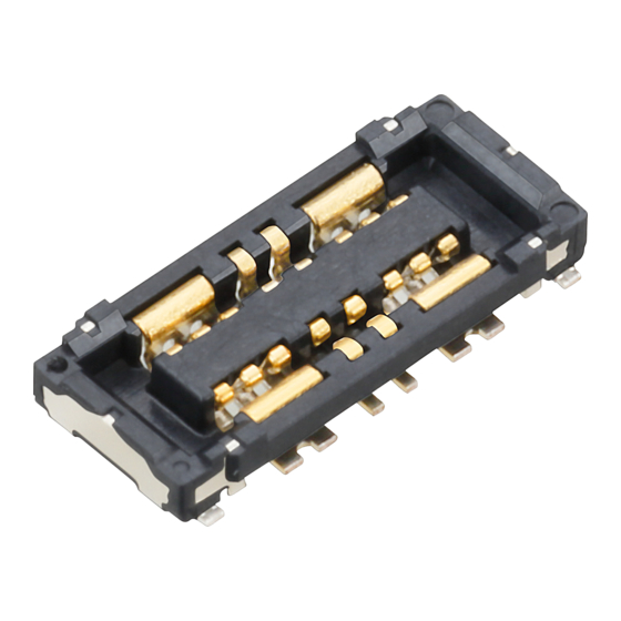
01. Introduction Our B2B connector for battery is designed for a high-performance and quick battery charging of mobile device and a high electrical current of 6A(B01) or 10A(B02) is available. Furthermore, the shape is ultra-small and low-profile design . B01: stacking height of 0.6mm / 0.8mm , width of 2.4mm B02:... -
Page 4: Precautions For Product Design
Operation manual for “High Current connectors B01/B02” 02. Precautions for product design 02-1. Considerations in mechanical design 1) Prevention of problems during use (1)The connectors have a simple locking structure, but make sure to consider preventive measures against the detachment of mated connectors during practical use. - Page 5 Operation manual for “High Current connectors B01/B02” (2)If the board is insufficiently fixed as in the following drawing, the inertial load applied to the connector may damage it. Pay attention to the following points. When an impact such as dropping as shown in the...
- Page 6 Operation manual for “High Current connectors B01/B02” (3)To facilitate the mating of connectors, we recommend that you pay attention to the following points when designing the motherboard. - Provide a reference mark. - Design a layout that allows easy-checking of the connector mating condition.
- Page 7 Operation manual for “High Current connectors B01/B02” 02-2. Precautions for board design 1) Circuit design (1)When designing the terminal foot pattern, check the latest specifications and examine the recommended foot pattern and dimensions of the metal mask opening. The current recommendations are indicated on pages 12 to (2) The power terminal consists of 4 pins.
- Page 8 Operation manual for “High Current connectors B01/B02” (3)This connector is provided with soldering metals for preventing solder from peeling off the terminal. Make sure to design a foot pattern for the holding metal. Socket Header Soldering terminal Soldering terminal (4)Pay attention to the following point as a pattern peeling preventive measure when removing the connector.
- Page 9 Operation manual for “High Current connectors B01/B02” 2) FPC board design (1)Positions of connectors on the FPC The FPC board is made by laminating a polyimide layer, copper foil, and adhesive layers. Since each material has slightly different heat-shrinkable properties, warpage may occur typically due the reflow heat in the following cases.
- Page 10 Operation manual for “High Current connectors B01/B02” (2)FPC board specifications Control the thicknesses of the coverlay and adhesive to prevent poor soldering. This connector has no stand-off. Therefore, minimize the thickness of the coverlay, etc. so as to prevent the occurrence of poor soldering.
- Page 11 Operation manual for “High Current connectors B01/B02” 3) Reinforcing plate design We recommend the use of a reinforcing plate with appropriate thickness and rigidity to prevent solder peeling and pattern peeling when unmating the connector, and to guard against board warpage during the reflow process.
- Page 12 Operation manual for “High Current connectors B01/B02” Metal Mask Design Since this connector is designed with an ultra low-profile, pay attention to the following precautions for reflow soldering. (1)In addition to the amount of applied solder, the reflow-soldering environment and temperature profile affect the finish quality after reflow soldering.
- Page 13 Operation manual for “High Current connectors B01/B02” Recommended specifications for PC-board and metal mask opening area When designing please verify with the product specification sheets ①B01 Socket [mating height 0.6mm/0.8mm] Recommended PC-board pattern (Mount-pad layout)(TOP VIEW) Recommended metal mask pattern When the metal mask thickness is 100μm...
- Page 14 Operation manual for “High Current connectors B01/B02” Recommended specifications for PC-board and metal mask opening area ②B01 Header [mating height 0.6mm/0.8mm] Recommended PC-board pattern (Mount-pad layout)(TOP VIEW) Recommended metal mask pattern When the metal mask thickness is 100μm (Power contact section opening area: 73%)
- Page 15 Operation manual for “High Current connectors B01/B02” Recommended specifications for PC-board and metal mask opening area When designing please verify with the product specification sheets ③B02 Socket [mating height 0.7mm] Recommended PC-board pattern (Mount-pad layout)(TOP VIEW) Recommended metal mask pattern When the metal mask thickness is 100μm...
- Page 16 Operation manual for “High Current connectors B01/B02” Recommended specifications for PC-board and metal mask opening area ④B02 Header [mating height 0.7mm] Recommended PC-board pattern (Mount-pad layout)(TOP VIEW) Recommended metal mask pattern When the metal mask thickness is 100μm (Power contact section opening area: 71%)
-
Page 17: Precautions For Mounting And Reflow Soldering
Operation manual for “High Current connectors B01/B02” 03. Precautions for mounting and reflow soldering 03-1. Mounting When mounting, a multifunctional mounter is recommended If using a high-speed mounter, controle the suction force by using a multifunctional head In case of dry condition, please note the occurrence of static electricity. - Page 18 Operation manual for “High Current connectors B01/B02” ■B02 Mated height: 0.7mm ●Examples of suction nozzle shape ① Elongated hole ② Circular hole Available for except for the case of connector turning around when mounted. ●Connector weight (socket) Mated height:0.6mm Mated height:0.8mm (Unit;g)...
- Page 19 Operation manual for “High Current connectors B01/B02” 2) Picking up the header (1)The suction area on the header is 0.7 mm in the shorter direction. If it is difficult to reliably insert the nozzle to the connector bottom face of 0.7 mm widthwise, the header can be picked up by converting the entire top face of the connector as shown below.
- Page 20 Operation manual for “High Current connectors B01/B02” ●Examples of suction nozzle shape ② Circular hole ① Elongated hole (Unit;mm) Available for less except Pins for the case of connector turning around when mounted. *It is available to suck the connector’s whole top surface.
- Page 21 Operation manual for “High Current connectors B01/B02” 03-3. Precautions for reflow soldering (1)Measure the temperature profile at the mounted connector position, and make sure that it conforms to the recommended profile. (2)When the molded part of connector melts or becomes deformed during the reflow process, the heating temperature may be too high, or the connector may be affected by a nearby electronic component with high heat capacity.
- Page 22 Operation manual for “High Current connectors B01/B02” 03-4. Precautions for manual soldering and solder rework The size of this connector has been reduced in order to achieve a narrow pitch and save space. Therefore, take great care when carrying out manual soldering or rework.
- Page 23 Operation manual for “High Current connectors B01/B02” 03-5. Detailed precautions for solder rework (1)Flux-applying tool To prevent solder creeping to a contact section, we recommend the use of a brush pen that can apply an appropriate amount of flux. (e.g., BON-102F, Japan Bonkote)
- Page 24 Operation manual for “High Current connectors B01/B02” 03-6. Detailed precautions for manual soldering (1)General precautions - When applying flux, apply it thinly on each foot pattern using a brush pen as shown on the previous page. (Place the connector at a predetermined position after applying flux.)
- Page 25 Operation manual for “High Current connectors B01/B02” 03-7. Flux cleaning method of PC board There is no need to clean this product. If cleaning, pay attention to the following points to prevent the negative effect to the product (1)In order to keep the solvent purity and to enhance cleaning, prepare equipments such as boil, ultrasonic cleaning with cold solvent and vapor washing.
-
Page 26: Precautions For Mating And Unmating
Operation manual for “High Current connectors B01/B02” 04. Precautions for mating and unmating 04-1. Precautions for mating This connector features a compact and thin design. Although it is designed to be easily handled, follow the rules for mating below to avoid damage to the molded part and buckling or deformation of the contact. - Page 27 Operation manual for “High Current connectors B01/B02” (6) Do not remove or insert the electrified connector. (in the state of carrying current or applying voltage) (7) Electric Shock Hazard Power terminal of header side is exposed. So if you touch the power terminal with finger (ex. mating operation), the battery may electrical short and get an electrical shock.
- Page 28 Operation manual for “High Current connectors B01/B02” 04-2. Precautions for connector unmating (1)Hold the reinforcing plate at unmating the connector. (2)Lift straight up to unmate. Lift up (3)If the method of unmating described above is not feasible due to a lack of space around the connector, please lift around one of the shorter sides of the connector to unmate it.
- Page 29 Operation manual for “High Current connectors B01/B02” Amendment history Manual No. Date Changes ACCTF34E Preliminary Oct, 2017 Panasonic Corporation Electromechanical Control Business Division © ACCTF34E 201710 Panasonic Corporation 2017 industrial.panasonic.com/ac/e/...
- Page 30 2017 ACCTF34E 201710...