
Related Manuals for Panasonic P4S


Summary of Contents for Panasonic P4S
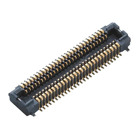
- Page 1 Narrow-pitch Connectors P4S Shield type Operation manual ACCTF24E-1 2017.10 industrial.panasonic.com/ac/e/...
- Page 2 Operation manual for Narrow-pitch connectors P4S Shield type Contents 01.Introduction ..................... 2 02.Precautions for equipment design ............3 03.Precautions for mounting and reflow soldering ........15 04.Precautions for mating ................23 Parts that require special confirmation are bold and underlined.
-
Page 3: Introduction
1.5 mm, and width of 3.8 mm. Being both slim and equipped with a shield plate, the P4S Shield type connector is designed for use in the connections between PC boards and PC boards, and PC boards and flexible PC boards, compared to our P4S series, noise immunity are required. -
Page 4: Precautions For Equipment Design
Otherwise, misaligned connector positions may cause mating failure or product breakage. Panasonic corporation does not guarantee the failures caused by using the multiple connectors. (2)Solid board is tend to warp to vertical direction against mill direction of production process. - Page 5 Operation manual for Narrow-pitch connectors P4S Shield type 2) Position of connectors during mounting When using a multiple-pin connector, it is preferable that the connector be placed in a position that does not require swing motion of the mounter during pickup and mounting.
- Page 6 Operation manual for Narrow-pitch connectors P4S Shield type 3) Prevention of problems during equipment operations (1) Although this product is equipped with a simple locking mechanism, insert cushioning material in the equipment enclosure in order to prevent the header from being detached from the socket or damaged during operation.
- Page 7 Operation manual for Narrow-pitch connectors P4S Shield type (3) For an easier connecting operation, it is recommended that the main board be designed as follows: - Provide a positioning mark. - Place the connector in a position where a connector mating operation can be easily checked.
- Page 8 Operation manual for Narrow-pitch connectors P4S Shield type 02-2. Board design 1) Circuit design Since this connector has multi-point ground construction, there is a dedicated ground terminal. When designing the terminal foot pattern, check the latest specifications and examine the recommended foot pattern and dimensions of the metal mask opening.
- Page 9 Operation manual for Narrow-pitch connectors P4S Shield type (4) Precautions for placing a through hole in prohibited area. Header is constructed as shown in below, the post is extended to the bottom of body and metal part of the terminal is exposed horizontally on the area from the post on the bottom of body to the middle of foot pattern.
- Page 10 Operation manual for Narrow-pitch connectors P4S Shield type Please consider the following points when providing a through hole by extending the foot pattern. If a through-hole is created simply by extending the foot pattern by the same width, solder is...
- Page 11 Operation manual for Narrow-pitch connectors P4S Shield type 2) Flexible PC board design (1) Positions of connectors on the FPC FPC consists of polyimide, copper foil and bond layer. Each contraction rate of those material by heat is different so that warp of FPC may occurred and may cause poor soldering.
- Page 12 Operation manual for Narrow-pitch connectors P4S Shield type (2) Flexible PC board specifications Control the thicknesses of the coverlay and adhesive to prevent poor soldering. There is a clearance of approx. 0.05 mm between the bottom surface of the terminal and the mold casing. Therefore, minimize the coverlay thickness, otherwise poor soldering may be result.
- Page 13 Operation manual for Narrow-pitch connectors P4S Shield type 3) Support plate design Select a support plate with an appropriate thickness and hardness to prevent solder or the pattern from being removed during unmating of the connector. (1) It is recommended to use stainless or glass-reinforced epoxy plates, which can easily provide adequate hardness.
- Page 14 Operation manual for Narrow-pitch connectors P4S Shield type 4) Metal Mask Design Since this connector is designed with compact and narrow pitch, please pay attention to the following precautions for reflow soldering. (1) In addition to the amount of applied solder, the reflow-soldering environment and temperature profile affect the finish quality after reflow soldering.
- Page 15 Operation manual for Narrow-pitch connectors P4S Shield type Recommended specifications of mounting pattern on PC board and window size of metal masking Please refer to the latest product specifications when designing your product. Product: Narrow pitch connector P4S Shield type Socket...
- Page 16 Operation manual for Narrow-pitch connectors P4S Shield type Recommended specifications of mounting pattern on PC board and window size of metal masking Product: Narrow pitch connector P4S Header (When using shield type socket) Stacking height 1.5 mm type Recommended mounting pattern on PC board (Top view)
-
Page 17: Precautions For Mounting And Reflow Soldering
Operation manual for Narrow-pitch connectors P4S Shield type 03. Precautions for mounting and reflow soldering 03-1. Mounters When mounting, a multifunctional mounter is recommended If using a high-speed mounter, controle the suction force by using a multifunctional head In case of dry condition, please note the occurrence of static electricity. - Page 18 Operation manual for Narrow-pitch connectors P4S Shield type Nozzle tip shape example (1) Nozzle tip shape example for sockets side. Size of nozzle tip ① Circular nozzle tip Note: It is possible to pick up the cover in calculation theory.
- Page 19 Operation manual for Narrow-pitch connectors P4S Shield type 03-3. Precautions for reflow soldering (1) Check the actual temperature profile at the connector mounting position and check that it matches the recommended temperature profile. Temperature Time When the resin part of the connector is melted or deformed during reflow...
- Page 20 Operation manual for Narrow-pitch connectors P4S Shield type 03-4. Manual soldering and Solder rework This connector has been miniaturized in order to achieve a narrow pitch and an ultra- low profile. Therefore, take great care when carrying out manual soldering or rework.
- Page 21 Operation manual for Narrow-pitch connectors P4S Shield type 03-5. Detailed precautions for solder rework (1) Flux-applying tools In order to prevent solder from rising to the contact section, the use of a brush pen type flux applicator that allows an appropriate amount of solder to be applied is recommended.
- Page 22 Operation manual for Narrow-pitch connectors P4S Shield type 03-6. Detailed precautions for manual soldering (1) General precautions - When applying flux, apply it thinly on each foot pattern using a brush pen as shown on the previous page. (Place the connector at a predetermined position after applying flux.)
- Page 23 Operation manual for Narrow-pitch connectors P4S Shield type 03-7. Cleaning flux from PC board Cleaning this product is not needed. If cleaning it, pay attention to the following points to prevent the negative effect to the product. 1) To increase the cleanliness of the cleaning fluid and cleaning operations, prepare equipment for cleaning process beginning with boil cleaning, ultrasonic cleaning, and then vapor cleaning.
-
Page 24: Precautions For Mating
Operation manual for Narrow-pitch connectors P4S Shield type 04. Precautions for mating 04-1. Precautions for mating This connector features a compact and thin design. Although it is designed to be easily handled, follow the rules below to avoid damage to the resin part and buckling or deformation of the contact. - Page 25 Operation manual for Narrow-pitch connectors P4S Shield type The fitting operation shown below may cause problems, and should thus be avoided. - Deformation of the contacts and post - Generation of molded resin deformation and resin particles, causing contact failures due to debris and spring return failures due to resin deformation.
- Page 26 Operation manual for Narrow-pitch connectors P4S Shield type Due to the place or space of actual equipment, if it is difficult to mate straightly while keeping the boards flat, please follow the way as shown below. (1) Please fit the pitch of socket and header slanting toward shorter direction and do the position adjustment.
- Page 27 Operation manual for Narrow-pitch connectors P4S Shield type 04-2. Precautions for unmating the connector (1) Hold the support plate when unmating the connector. GOOD! WRONG! (2) Please lift as vertical as possible. Pulling up (3) To reduce the stress applied to the soldered terminal and connector, the use of an unmating jig, shown on the following page, is also recommended.
- Page 28 Operation manual for Narrow-pitch connectors P4S Shield type Amendment history Manual No. Date Changes ACCTF24E First version June, 2015 ACCTF24E-1 Revised (Index, P.3, P.14, 15) Oct, 2017 Panasonic Corporation © ACCTF24E-1 201710 industrial.panasonic.com/ac/e/ Panasonic Corporation 2017...
- Page 29 2017 ACCTF24E-1 201710...