
Related Manuals for FE FSH


Summary of Contents for FE FSH
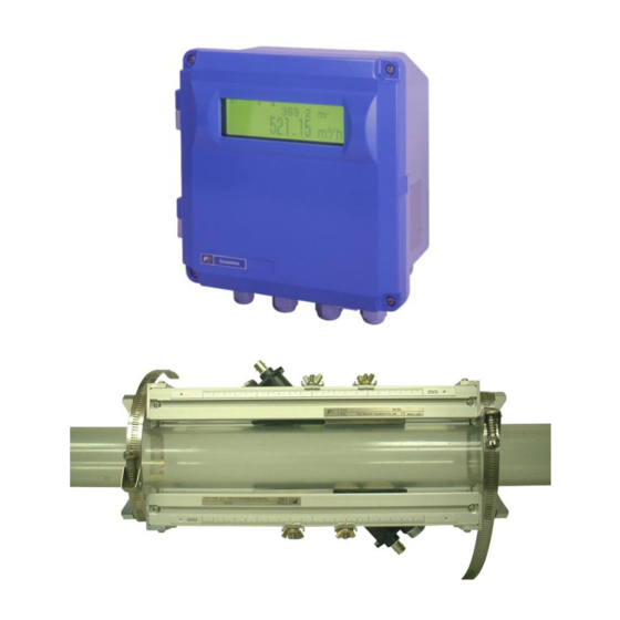
- Page 1 Instruction Manual HYBRID ULTRASONIC FLOWMETER <Duosonics> TYPE: FSH (Flow transmitter) FSW (Detector) FLY (Signal cable) INF-TN1FSHa-E...
-
Page 2: Preface
The instruction manual concerns the installation, operation, checkup and maintenance of the Flow transmitter (FSH) and Detector (FSW) of ultrasonic flowmeter. Read it carefully before operation. • Before using, be sure to read this instruction manual carefully to ensure correct installation, operation and maintenance of the flowmeter. -
Page 3: Safety Precaution
SAFETY PRECAUTION Before using, read the following safety precaution to ensure correct handling of the flowmeter. • The following items are important for safe operation and must be fully observed. These items are classified into "DANGER" and "CAUTION". Warning & Symbol Meaning ANGER Incorrect handling may lead to a risk of death or heavy injury. - Page 4 Caution on Wiring AUTION • When performing wiring termination to prevent output trouble caused by moisture, dew condensation or water leak, follow “Section 3.3. Flow transmitter wiring” described in this manual • Before performing the wiring work, be sure to turn OFF the main power to prevent electric shocks.
-
Page 5: Caution On Installation Location
A place that provides enough place for the length of the straight pipe. (10) A place where ambient temperature and humidity are • 10 to +50°C and 90% RH or less for flow transmitter (FSH), and • 20 to +80°C and 100% RH or less for detector (FSW). - iv -... -
Page 6: Table Of Contents
Contents PREFACE..................................I SAFETY PRECAUTION ..............................II CAUTION ON INSTALLATION LOCATION......................IV 1. PRODUCT OUTLINE..............................1 1.1. Outline..................................1 1.1.1. Measurement principle............................1 1.2. Checking delivered items ............................3 1.3. Checking type and specifications..........................4 1.4. Names of each part and functions ..........................7 2. SELECTING INSTALLATION LOCATION ......................9 2.1. - Page 7 4.4.9.1. Total unit..............................62 4.4.9.2. Setting total pulse (Total rate, pulse width) ..................... 63 4.4.9.3. Total preset .............................. 65 4.4.9.4. Total SW..............................66 4.4.9.5. Determining how to dispose of total at error (BURNOUT) ..............67 4.4.10. Flow switch ..............................68 4.4.11.
- Page 8 7.5.1. Communications ............................116 7.5.2. Setting ................................117 7.5.2.1. Save setting ............................117 7.5.2.2. Read setting............................117 7.5.3. Version ................................118 7.6. Structure of Function............................118 7.7. Establish Setting..............................119 7.8. Range Setting ...............................121 7.9. Total Setting .................................123 7.10. Status Output Setting............................125 7.11. Display Setting ..............................126 7.12. System Setting..............................127 7.13.
-
Page 9: Product Outline
1. PRODUCT OUTLINE 1.1. Outline This high precision flowmeter is the world’s first clamp-on type ultrasonic flowmeter that adopts the pulse Doppler method and the transit time method as its measurement principles. The ultrasonic flowmeter for industrial use employs the pulse Doppler method, which directly measures flow distribution, thus easing straight pipe conditions and allowing measurement of flows that have not grown into eddy or laminar flow. - Page 10 Configuration (1) 1 measurement line method (Z method) Cable Power supply Detector 4 to 20 mA DC Contact (3 points max.) Temperature sensor cable (2) 2 measurement line method (Z method) Power Cable supply Detector 4 to 20 mA DC Contact (3 points max.) Temperature sensor cable - 2 -...
-
Page 11: Checking Delivered Items
1.2. Checking delivered items Flow transmitter (FSH) Detector (FSWS50) Flow transmitter main unit ··································1 set Detector main unit (FSWS50)····························· 1 set Waterproof gland (Built into the main unit) ·········1 set Absorber unit ······················································ 1 set Wall mount fittings (Built into the main unit) ······1 set Wire rope····························································... -
Page 12: Checking Type And Specifications
The specification plates attached to the flow transmitter and the detector list the type and specifications of the product. Check that they represent the type you ordered, referring to the following code symbols. < Flow transmitter (FSH)> 1 2 3 4 5 6 7 8... - Page 13 <Detector (FSW)> 1 2 3 4 5 6 7 8 9 10 11 Description Type (4th digit) Standard Kind of detector (5th and 6th digit) Small diameter detector (φ 40 to 200 mm) Small size detector (φ 100 to 400 mm) Middle size detector (φ...
- Page 14 <Signal cable (FLY)> 1 2 3 4 5 6 7 8 Description Kind of cable (4th digit) Coaxial cable (for ultrasonic sensors) 1 pair (2 pcs.) Three-core cable (for temperature sonsor) Cable length (5th to 7th digit) 100m 110m 120m 130m 140m 150m...
-
Page 15: Names Of Each Part And Functions
1.4. Names of each part and functions (12) (10) (11) (23) (14) (15) (13) (17) (18) (22) (16) (21) (19) (20) Name Description Wiring connection port for power cable Wiring port for power cable Wiring connection port for ultrasonic signal Wiring port for ultrasonic signal cable cable Wiring connection port for temperature... - Page 16 Name Description Retainer plate Used for fastening the sensor by pressing it against the piping. (15) BNC connector for ultrasonic signal cable Transmits ultrasonic send/receive signals. (16) Water-tight connector for temperature Transmits temperature sensor signals. (17) sensor cable Stainless steel belt Used for fastening the sensor frame to the piping.
-
Page 17: Selecting Installation Location
AUTION (1) A place where ambient temperature and humidity are as follows: Flow transmitter (FSH): −10 to +50°C, 90%RH or lower Detector (FSW): −20 to +80°C, 100%RH or lower (2) A place not subject to direct sunlight or weather (3) A place provided with space for daily inspection and wiring work (4) A place not subject to radiant heat from a heating furnace, etc. -
Page 18: Detector
2.2. Detector The mounting position of the detector, in other words, the state of the piping where the flow rate is to be measured, affects the accuracy of measurement to a great extent. Select a place that satisfies the conditions described in 2.2.1. Length of straight section of pipe. -
Page 19: Length Of Straight Section Of Pipe
2.2.1. Length of straight section of pipe To assure the accuracy of flow rate measurement, allow sufficient length of the straight section of the pipe on the upper/lower stream side, referring to “straight pipe conditions” shown below. ( D : Inside diameter of pipe) Classification Upstream side Downstream side... -
Page 20: Mounting Position
2.2.2. Mounting position The instrument can be mounted horizontally or in any other position. However, pay attention to the following. (1) Allow fluid to fill the pipe and keep it flowing at all times. The pipe may not be filled with fluid. Air tends to pile up. -
Page 21: Mounting The Sensor
2.2.3. Mounting the sensor The detector can be mounted Z method as shown in Fig. 1. As shown in Fig. 2, the center of the cap screw of the sensor is a reference. The mounting spacing of the two sensors corresponds to the V-shaped portion in Fig. -
Page 22: Installation And Before Start Of Operation
3. INSTALLATION AND BEFORE START OF OPERATION 3.1. Before operation (1) Selection of installation location of flow transmitter and detector (2) Installation and wiring of flow transmitter (3) Power ON Check the power supply specifications and wiring before turning on the power. (4) Entering of piping parameters and calculation of the sensor spacing (*Check the sensor spacing if parameter setting is provided.) (5) Mounting of frame to measurement piping (*When using a frame for mounting) -
Page 23: Installing The Flow Transmitter
3.2. Installing the flow transmitter The flow transmitter can be mounted on a wall or on a panel. Use four M8 bolts to mount the flow transmitter on a wall or a panel. Drill holes according to the mounting hole dimensions shown below, and fasten the flow transmitter using the M8 bolts. -
Page 24: Flow Transmitter Wiring
(1) Use a dedicated cable (FLY) as a signal cable between the detector (FSW) and the flow transmitter (FSH). Do not join cable in the middle. (2) Be sure to let the signal cables installed between the detector and the flow transmitter run through a metal conduit tube. -
Page 25: Removing And Mounting The Cover And The Shield Plate
3.3.4. Removing and mounting the cover and the shield plate Before installing wiring, loosen the 2 M4 screws and remove the cover. Screw Cover Remove the 4 M3 screws and then the shield plate. Shield plate Screw On completion of wiring work, be sure to mount the shield plate and the cover. AUTION •... -
Page 26: Wiring To Each Terminal
3.3.5. Wiring to each terminal Install wiring according to the layout shown below. Power board terminal block Power supply terminal (AC) 100 to 200 V AC Power supply terminal (DC) 20 to 30 V AC Outer earth terminal ignal terminal [Control board terminal block] ERIAL Iout... -
Page 27: Setting Piping Parameters And Calculating The Sensor Spacing
3.4. Setting piping parameters and calculating the sensor spacing Make the setting to calculate the sensor spacing as follows. 3.4.1. Selecting sensor type, mounting the sensor, setting the sensor constant Description The data of the sensor required for measurement can be set as follows. If the sensor mounting method or sensor type is changed, the sensor spacing in piping specifications is also changed. - Page 28 Operation (example) When Z method as sensor mount, FSW12 as sensor type, 102% for sensor constant line 1-F (METAL), 101% for 1-R (METAL) Key operation Description Display Display System. UNIT & LANGUAGE FUNC SYSTEM SKIP Select “SENSOR MOUNT” SENSOR MOUNT "...
-
Page 29: Entering Piping Specifications
3.4.2. Entering piping specifications Description By setting the conditions of the piping where measurement is to be taken, the sensor spacing to be mounted can be calculated. The sensor spacing is calculated automatically. Enter data for each item listed in the following table according to the display. Item Input method Range or menu... - Page 30 Enter select/enter mode, select “CARBON PIPE MATERIAL ENTER " or # ENTER STEEL,” and then press ENTER. CARBON STEEL Select “WALL THICKNESS” WALL THICKNESS 4.50 mm Enter numeric value enter mode, enter “6” WALL THICKNESS ENTER 6 ENTER using ten keys, and press ENTER. 6.00 mm Select “LINING MATERIAL”...
-
Page 31: Installing Detector
3.5. Installing Detector 3.5.1. Outline of detector installation procedure 1. Treatment of mounting surface of the detector 2-1 Mounting small-diameter and small/medium size sensor (1) How to mount the frame (using a jig) (2) How to mount the frame (not using a jig) (2)-1 How to determine the mounting position (2)-2 How to mount the frame (3) How to mount the sensor unit... - Page 32 (3) Fasten the mounting jig to the frame using the (6) Let the shaft run through the mounting jig on the butterfly nut and the screw. opposite side. Butterfly nut Screw (7) Place the frame between the pipes. (4) Mount the mounting jig on the opposite side of the frame.
- Page 33 (9) Wrap the stainless belt around the frame end. (12) Fasten both ends of the frame with the stainless belt. Frame end (13) Remove the mounting jig. Remove the shaft first, and then remove the (10) Lift the screw of the stainless belt to let the tip of the mounting jig.
- Page 34 (2) How to mount the frame (not using a jig) Gage paper is required to mount the frame by this method. (See “8.7. Making gauge paper” for details.) (2)-1 How to determine the mounting position Align the edge of the gauge paper to the 100mm place 100mm from one of the edges treated for mounting, and wrap it around the pipe, keeping...
- Page 35 (2)-2 Mounting the Frame (1) Checking the mark-off line “In the case of 1 measurement line” “In the case of 2 measurement lines” Draw a mark-off lines at an angle ± 45 ° Draw a horizontal mark-off line that includes the center point of the cross from the horizon.
- Page 36 (3) How to mount the sensor unit Mount the sensor unit comprising of two sensors facing opposite to each other, keeping the spacing displayed after the piping parameter setting is completed. See “2.2.3. Mounting the sensor” for details. Note: Mount the sensor unit equipped with a temperature sensor on the upstream side. If plastic piping is used, the absorber unit is not required.
- Page 37 (5) Fix the absorber unit with the cap screws so that the (9) Connect the ultrasonic signal cable to the BNC absorber unit comes in contact with the sensor unit. connector, being careful not to reverse the upstream and the downstream wiring. Downstream side Ultrasonic signal cable The absorber unit...
-
Page 38: Mounting The Sensor Unit By Z Method Using A Frame (2 Measurement Lines)
3.5.4. Mounting the sensor unit by Z method using a frame (2 measurement lines) (1) Mounting the frame Two pairs of frames are required. (1) Draw a mark-off line at an angle ± 45 ° from the horizon. See 3.5.5. (1) how to draw a mark-off line. Mark-off line Frame 45°... -
Page 39: Mounting The Sensor Unit To A Large-Diameter Pipe
3.5.5. Mounting the sensor unit to a large-diameter pipe (1) How to determine the mounting position Do not use a mounting jig to install the sensor unit to a pipe of diameter of 500 A or more. Mount the sensor with wire in such cases. - Page 40 (2) Mounting the sensor Use sensor FSW50 for large-diameter pipes. Note: Mount the sensor unit equipped with a temperature sensor on the upstream side. (1) Checking the mark-off line “In the case of 1 measurement line” “In the case of 2 measurement lines” Draw a mark-off lines at an angle ±...
- Page 41 (5) Apply silicon rubber evenly over the entire The absorber unit is not required for resin piping. ultrasonic transmission surface and the contact Proceed to (11) in this case. surface of the temperature sensor piping, being The absorber unit is used for metal piping. Proceed careful not to let air bubbles mix in.
- Page 42 (10) Adjust the position by aligning the match mark of (12) Connect the temperature sensor cable to the the absorber unit and the sensor unit with the waterproof connector for the temperature sensor marking line. cable. (13) Connect the ultrasonic signal cable to the BNC Marking line connector of the sensor unit, being careful not to reverse the wiring on upstream and downstream...
-
Page 43: Setting Analog Output Range And Total Pulse
3.6. Setting analog output range and total pulse The following table lists the analog output and total pulse settings. 3.6.1. Analog output range setting Description Make the setting as shown below when outputting the measured value (flow rate or flow velocity) in specified range within 4 to 20 mA. - Page 44 Enter numeric value enter mode, enter “30” BURNOUT TIMER ENTER 3 0 ENTER using ten keys, and press ENTER. 30 sec Select “RATE LIMIT” RATE LIMIT 0.00 m Enter numeric value enter mode, enter “5,” RATE LIMIT ENTER 5 ENTER and press ENTER.
-
Page 45: Total Pulse Output Setting
3.6.2. Total pulse output setting Description Make the setting to perform pulse output of the total measurement value (flow rate). The following is an example of operation. Refer to 4.4.9. and 4.4.11. for details of the setting. Definition of total pulse to DO When DO1 is output as total pulse output in forward direction (example) Key operation... -
Page 46: Zero Adjustment
Enter select/enter mode, select “100,” and PULSE WIDTH 1 ENTER " or # ENTER press ENTER. 100 msec Select “TOTAL MODE” TOTAL MODE " or # TOTAL STOP Enter select/enter mode, select “TOTAL TOTAL MODE ENTER " or # ENTER RESET,”... -
Page 47: Setting Parameters
4. SETTING PARAMETERS 4.1. Description of display/setting unit 4.1.1. Description of display Turn on the power, and the following display appears. The meaning of displayed numeric values and symbols are as follows. Measurement screen RAS display Measurement method Display 0 000 .... - Page 48 Table 1 Description of keys Name Description 0 to 9 , ・ , Ten key Used to enter numeric values for data and piping specifications. ± Press this key to set the numeric data entered using keys or ENTER ENTER items selected by dialog.
-
Page 49: Setting Item List
4.2. Setting item list Refer to Appendix “8.5. Composition of key operation” for details of composition of key operation. Measurement Piping specifications 4.4.2. screen ( FUNC PIPE ) Output setting Range unit, range type, full scale 4.4.4.1. Output limit 4.4.4.2. ( FUNC RANGE ) BURNOUT 4.4.4.3. -
Page 50: Parameter Specification Table
4.3. Parameter specification table The following table lists factory settings (not applicable to the type with parameter settings). Setting item Settable range Initial value Settable value Outer diameter 10.00 to 6200.00 mm 60.00 mm [mm, inch] (0.393 to 244.100 inch) (2.362 inch) Pipe material 12 menus... - Page 51 Setting item Settable range Initial value Settable value Low flow cut off 0.00 to 5.00m/s (0.00 to 0.01 m/s [(19) Unit] 16.40 ft/s) in terms of flow (0.03 ft/s) velocity Total mode 3 menus Total stop Total stop, Total run, Total reset Total unit 8 menus mL (ft...
- Page 52 Setting item Settable range Initial value Settable value Measure method 2 menus Hybrid Hybrid, Transit time Measurement 2 menus Depends on 1 Path, 2 Path mode the detector specification. AO definition 3 menus Depends on Average, Line 1, Line 2 the detector specification.
-
Page 53: Setting Parameters
4.4. Setting parameters The units are displayed in metric or English system. Description Parameters can be set by entering numeric values or by selection. Setting item Input method Range or menu Numeric Direct input Outer diameter of pipe specifications, etc. can be entered directly. •... - Page 54 Item selection When selecting carbon steel as pipe material (example) Key operation Description Display Select “PIPE MATERIAL” PIPE MATERIAL STAINLESS STEEL Enter select/enter mode. PIPE MATERIAL ENTER ▲ STAINLESS STEEL ▼ Select “CARBON STEEL” PIPE MATERIAL " or # ▲ CARBON STEEL ▼...
-
Page 55: Measurement Method And Sensor
4.4.1. Measurement method and sensor (Measurement method, sensor mount, sensor type, sensor constant, transmission voltage) Description Measurement method and sensor data required for measurement can be set as follows. If the sensor mount or the type of sensor is changed, the sensor spacing in “4.4.2. Pipe specifications” is also changed. AUTION Be sure to make the following parameter setting before mounting the sensors to the pipe. - Page 56 Sensor 3 Sensor 2 To line 1 To line 2 Direction of flow Sensor 1 Sensor 4 2-path system (Z method) *4) Select sensor constant only when the sensor type is selected from FSW12, FSW21, FSW40, and FSW50. Operation When hybrid is selected as measurement method, Z method as sensor mount, FSW12 as sensor type, (example) 102% for sensor constant line 1-F: (METAL), 101% for 1-R: (METAL), and 160Vpp as transmission voltage...
-
Page 57: Pipe Specifications
4.4.2. Pipe specifications Description Pipe data required for measurement can be set as follows. The sensor spacing is automatically calculated. AUTION Be sure to make the following parameter setting before mounting the sensors to the pipe. Mount the sensors, observing the specified sensor spacing. •... - Page 58 Select “LINING MATERIAL” LINING MATERIAL NO LINING Enter select/enter mode, select “TAR LINING MATERIAL ENTER " or # ENTER EPOXY,” and press ENTER. TAR EPOXY Select “LINING THICKNESS” LINING THICKNESS 0.01 mm Enter numeric value enter mode, enter LINING THICKNESS ENTER 1 .
-
Page 59: Measurement Mode (Measurement Mode, Ao Definition)
4.4.3. Measurement mode (Measurement mode, AO definition) Description Measurement can be taken using either 1 sensor (1 path) or a pair of sensors (2 path). When a pair of sensors is used, one from average, line 1, and line 2 can be selected for measurement calculation such as flow rate. Item Input method Range or menu... -
Page 60: Output Setting
4.4.4. Output setting 4.4.4.1. Range (range unit, range type, full scale, hysteresis) setting Description Make output setting to output measured value (flow rate or velocity) within specified range from 4 to 20 mA. (Measurement contents) (1) Selecting range unit Select one from the following units (metric system) L/s, L/min, L/h, L/d, kL/d, ML/d /s, m /min, m... - Page 61 *3) Maximum measurement range in hybrid mode In the case of pulse Doppler method, the measurable range varies depending on the piping specifications and the type of sensors used. If the measurement is to be made by hybrid method, set the full scale within the range that does not exceed the measurement range.
- Page 62 Select “FULL SCALE 2” FULL SCALE 2 112.64 m Enter numeric value enter mode, enter FULL SCALE 2 ENTER ± 1 0 0 ENTER “100” using ten keys, and press ENTER. 100.00 m Select “HYSTERESIS” HYSTERESIS 10.00% Enter numeric value enter mode, enter “5” HYSTERESIS ENTER 5 ENTER using ten keys, and press ENTER.
-
Page 63: Output Limit
4.4.4.2. Output limit Description The upper limit and the lower limit of analog output can be set within the range from 0.8 mA to 23.2 mA (−20% to 120%). Analog output Upper limit 23.2mA 20mA Lower limit Flow rate -20% 100% 120% 0.8mA Operation... -
Page 64: How To Set Analog Output At Error (Burnout)
4.4.4.3. How to set analog output at error (BURNOUT) Description Output burnout is a function of setting the analog output to specific values shown below when the measurement status becomes abnormal. Set the duration until burnout processing is performed with the burnout timer. (Setting contents) •... -
Page 65: Rate Limit
4.4.4.4. Rate limit Description Spike noise input by slurry fluid, etc. can be cut before output. Rate limit: 0 to 5 m/s in velocity. Enter absolute value. Rate limit timer: 0 to 900 sec. Input Limit time Limit value Limit value Limit time Output Note 1: If the input exceeding the limit value continues for more than the limit time, it is regarded as valid signals and... -
Page 66: Damping
4.4.5. Damping Description Damping is used to suppress the fluctuation of measurement. Set it by time constant (response time of about 63%) (Setting range: 0.0 to 100.0%) Flow rate Time Response time Operation When set value is 20 sec. (example) Key operation Description Display... -
Page 67: Zero Adjustment
4.4.6. Zero adjustment Description The zero point of the measured value by time difference measurement can be adjusted as follows. (Setting contents) Zero: Perform zero adjustment in a state where the flow is stopped. The measurement status at the specified time is set as 0. Note: Perform adjustment in a state where the flow is stopped. -
Page 68: Display Setting
4.4.7. Display setting Description Measurement value to be displayed in display unit and display kind can be selected from the following. (1) Selection Measurement value to be displayed can be selected from the following. Velocity: Instantaneous velocity [m/s] Total forward * : Total value in forward direction Total reverse * : Total value in reverse direction... -
Page 69: Cut Off
4.4.8. Cut off Description The output can be cut when the flow rate is low. This flowmeter may display flow rate even when the fluid within the pipe is moving due to convection, etc. even if the valve is closed. Set the cut off value as required. (Setting range: 0 to 5 m/s in velocity. -
Page 70: Integration
4.4.9. Integration 4.4.9.1. Total unit Description The measurement value (flow rate) can be integrated as follows. (1) Total unit Select one from the following total units: mL, L, m , km , Mm , mBBL, BBL, kBBL Note: Set the total mode to total stop state to make the setting. -
Page 71: Setting Total Pulse (Total Rate, Pulse Width)
4.4.9.2. Setting total pulse (Total rate, pulse width) Description The measurement value (flow rate) can be integrated in response to the total pulse output from an integrating meter, etc. as follows. (1) Total rate: When the total volume reaches the value specified by the total rate, the total pulse value on the measurement screen is added, and 1 pulse is output for total pulse (volume). - Page 72 From condition 2 2 × Total pulse width [ms] 2 × 50 [ms] Total rate ≥ Full scale [m /s] × /s] × = 0.01 [m 1000 1000 = 0.001 [m ] = 1 [L] ........B The settable range of the total rate that satisfies both condition 1 and condition 2 is found to be as follows based on the result of calculations A and B.
-
Page 73: Total Preset
4.4.9.3. Total preset Description Total preset value can be set as follows. Reset the total mode, and the preset value is restored. • F: Total preset: Total preset value in forward direction • R: Total preset: Total preset value in reverse direction (Setting range: 0 to 9999999999.999) Note: Set the total preset value in a state where the total mode is set to stop. -
Page 74: Total Sw
4.4.9.4. Total SW Description This is a function of providing contact output when the total value reaches the set value. Set the total SW when selecting “F: TOTAL SW” or “R: TOTAL SW” in status output setting. • F: Total SW: Total SW value in forward direction •... -
Page 75: Determining How To Dispose Of Total At Error (Burnout)
4.4.9.5. Determining how to dispose of total at error (BURNOUT) Description Output burnout is a function of setting the total output to hold when measurement state becomes abnormal. Set the duration until burnout processing is performed with the burnout timer. (Setting contents) •... -
Page 76: Flow Switch
4.4.10. Flow switch Description (1) The flow switch is actuated when the instantaneous flow rate exceeds the specified value. Set the flow switch high and low values when selecting “FLOW SW HIGH” or “FLOW SW LOW” in status output setting Setting range: 0 to 32 m/s in velocity. -
Page 77: Status Output
4.4.11. Status output Description (1) Output Total pulse and status (measurement error or flow rate switch) output can be set as follows (common for DO1/DO2/DO3) 1. NOT USED: Contact output is not used. 2. SIGNAL ERROR: Outputs when measurement error occurs. 3. - Page 78 Operation When setting DO2 output to total pulse in forward direction and mode to reverse (example) Key operation Description Display Display “SELECT STATUS” SELECT STATUS FUNC STATUS DO.1 Select “DO.2” and press ENTER. SELECT STATUS ENTER " or # ENTER ▲...
-
Page 79: Output Calibration
4.4.12. Output calibration Description Measurement value can be calibrated arbitrarily. Zero point and span adjustment can be made. The adjustment range is as follows: Zero point: ± 5 m/s in velocity Span: ± 200% Measurement value and analog output value can be calculated using the following expression. Measurement value ×... -
Page 80: Measurement Unit
4.4.13. Measurement unit Description Measurement unit can be selected from metric system and English system. (Setting contents) • Meter: Metric system Unit of length:......mm Unit of velocity (S.V.):...m/s Unit of flow rate:....L/s, L/min, L/h, L/d, kL/d, ML/d, m /s, m /min, m /h, m /d, km... -
Page 81: System Language Selection
4.4.14. System language selection Description The system language to be displayed at the time of setting can be selected from the following 5: English, Japanese, German, French, and Spanish. Operation When selecting English (example) Key operation Description Display Display SYSTEM. UNIT &... -
Page 82: Setting Serial Communication (Rs232C/Rs485)
4.4.15. Setting serial communication (RS232C/RS485) Description Communication setting can be made as follows when using transmission function. Setting contents COM. SPEED, COM. PARITY, COM. STOP BIT, SERIAL METHOD, STATION NO. Setting range COM. SPEED: 9600bps, 19200bps, 38400bps COM. PARITY: NONE, ODD, EVEN COM. -
Page 83: Maintenance
4.4.16. Maintenance 4.4.16.1. Analog output adjustment and check Description Adjust the analog output so that the output becomes 4 mA when the flow rate is 0 and 20 mA when it is in full scale. Check that each output value in the range from −20% to 120% becomes 0.8 mA to 23.2 mA. Connect an ammeter to the IOUT terminal to perform the adjustment. -
Page 84: Checking Status Output
4.4.16.2. Checking status output Description Check the ON-OFF operation of the status output as follows. Setting contents: ON: Closes the contact, OFF: Opens the contact. CAUTION • Check if DO output can be changed before operation. Connect voltmeters to DO1, DO2, and DO3 terminals. Note: Refer to “4.4.11. -
Page 85: Calibrating Temperature Sensor
4.4.16.3. Calibrating temperature sensor Description The resistance of the wedge temperature measurement can be calibrated as follows. (Setting contents) Calibrate: Calibrates resistance value 100Ω (wedge temperature: 0°C) and resistance value 140Ω (wedge temperature: 100°C) Clear: Displayed under uncalibrated state or when calibration error has occurred. (The uncalibrated state cannot be restored after calibration.) Note: Temperature sensor specifications Measurement range: −40 to 100°C... -
Page 86: Checking Temperature Sensor
4.4.16.4. Checking temperature sensor Description Check the wedge temperature measurement as follows. Connect a resistor to temperature sensor terminals as shown by the figure in 4.4.16.3. Operation When connecting 100 Ω resistor and checking that the wedge temperature becomes 0 ° C (example) Key operation Description... -
Page 87: Test Mode
4.4.16.5. Test mode Description In the test mode, flow rate is artificially input to check the state of integration and the operation of the flow rate switch, etc. Set the target value as full scale, and the period until the target value is reached (tracking time) can be arbitrarily set. 0 to ±... -
Page 88: Lcd Backlight
4.4.17. LCD backlight Description The LCD backlight of the displayed screen can be selected from ON, OFF, and AUTO. If AUTO is selected, the backlight is set to ON when values are entered from the keyboard, and it is set to OFF on the measurement display screen. -
Page 89: Key Lock
4.4.18. Key lock Description A password can be set for the input on the setting screen. Select a 4-digit numeric value as a password. “.” entered 4 times as a password is regarded as a valid password. Note: If you forget the password, enter “.” 4 times to reset the key lock. Operation When enabling the key lock and setting “1234”... -
Page 90: Checking System Name
Check the system name as follows. (example) Key operation Description Display Display SYSTEM. UNIT & LANGUAGE FUNC SYSTEM SKIP Select “SYSTEM NAME” SYSTEM NAME " or # Check the system name. FSH**** Display the measurement ESC ESC (Measurement display screen) - 82 - INF-TN1FSH-E... -
Page 91: Details Of Measurement
4.4.20. Details of measurement 4.4.20.1. Transit time Description The data required for time difference measurement can be set as follows. [Signal processing outline drawing] Forward direction ultrasonic total time measurement Reverse direction ultrasonic total time measurement Send start (TXS) Measured Window open window Window... - Page 92 Item Input method Function and range or menu Window Setting of control method of measurement window that takes in signals control (Factory-set value: AUTO) Selection • AUTO • MANUAL Set the time of starting taking in signals (period from the start of transmission until the startup of window signals) •...
- Page 93 Operation When setting window control of line 2 to manual, open time (F/R) to 150 µ s, and measurement method (example) to method 1 Key operation Description Display Display VERSION INF. VERSION INF. FUNC DETAIL SKIP Select “TRANSIT TIME” TRANSIT TIME "...
-
Page 94: Pulse Doppler
4.4.20.2. Pulse Doppler Description The data required for pulse Doppler measurement can be set as follows. [Outline drawing of signal processing] Reference count Repetition frequency = 1/repetition cycle Transmissio n start (TXS) Repetition cycle Measurement window Window (RWIN) Signal wait time Echo wave Echo wave... - Page 95 Item Input method Function and range or menu Lining sound Setting of pipe sound velocity (Factory-set value: AUTO) velocity Selection • AUTO • MANUAL • PIPE S.V.: 1000m/s to 3700m/s Numeric value Transmission Setting of transmission frequency of the sensor (Factory-set value: AUTO) •...
- Page 96 Item Input method Function and range or menu Gain Setting of control method of demodulated wave gain (Factory-set value: AUTO) The peak of demodulated waves within measurement window is controlled not to exceed 3.2 Vpp. Selection • AUTO • MANUAL Make the setting so that the peak of demodulated waves within measurement window does not exceed 3.2 Vpp.
- Page 97 Operation When setting repetition frequency to 3500Hz manually and the success rate of line 1-F and line 1-R to (example) Key operation Description Display Display VERSION INF. VERSION INF. FUNC DETAIL SKIP Select “PULSE DOPPLER” PULSE DOPPLER " or # SKIP Enter select/enter mode, select WEDGE S.V.
-
Page 98: Initializing Setting Parameters
4.4.20.3. Initializing setting parameters Description Setting parameters stored in a memory can be initialized as follows. (Setting contents) • NOT INITIALIZE: Does not initialize the parameter. • FACTORY SETTING: Initializes those other than the adjusted values (such as current output, sensor constant, etc.) •... -
Page 99: Maintenance And Inspection
5. MAINTENANCE AND INSPECTION 5.1. Daily inspection Visually check the following. • Check the screw of the flow transmitter cover for looseness. ⇒ Fasten. • Check the cable gland for looseness. ⇒ Fasten. • Check the stainless belt of the detector for sag. ⇒... -
Page 100: Measuring Insulation Resistance
5.2.4. Measuring insulation resistance CAUTION Be sure to turn off the power before opening the cover of the flow transmitter. The power terminals (N, L) and the output terminals (Iout, SERIAL, DO1 to DO3) are provided with an arrester as standard. To measure the insulation resistance between the power terminal and the grounding terminal, remove the earth plate of the power terminal block as shown by the following figure. -
Page 101: Replacing Fuse
5.3. Replacing fuse CAUTION • Be sure to turn off the power before replacing the fuse. The specifications of the fuse is as follows: (1) AC power supply (100 V and 200 V): 5.2 mm (diameter) × 20 mm (length), 250 V 2A (Example: 0218 002 XP by Littelfuse) (2) DC power supply: 5.2 mm (diameter) ×... -
Page 102: Replacing Relay
5.4. Replacing relay DO3 is a relay contact, whose service life is 200,000 times (under rated load). Replace the relay before its service life expires, paying attention to the number of times of contact operation. Card relay type: RB104-DY (Fuji Electric) [Replacement procedure] (1) Turn off the power and open the cover. -
Page 103: Replacing Lcd
5.5. Replacing LCD The nominal service life of the LCD is 10 years. The contrast gradually deteriorates with time. Replace the LCD when 5 to 6 years have passed since the start of use. [Replacement procedure] (1) Turn off the power and open the cover. (2) Open the setting section of the display unit. -
Page 104: Troubleshooting
6. TROUBLESHOOTING 6.1. How to confirm normal operation 6.1.1. Checking on LCD If the following display does not appear, press the [ESC] key. Displayed symbol Operation status None Normal Device error (backup memory, wedge temperature measurement circuit) Measurement error (transit time error) Measurement error (pulse Doppler error) Range over, wedge temperature measurement error Displayed symbol... -
Page 105: Checking Measurement Status Information
6.1.2. Checking measurement status information 6.1.2.1. Checking and setting of RAS information Description (1) Checking of RAS information Check the details of error status. The following table lists the RAS information displayed on the upper-left corner of the measurement screen. If an error is detected, take measures according to “6.2. - Page 106 (2) Setting of RAS information Set the RAS information E1 to E4, which display abnormal condition, to “Valid” or “Invalid.” When set to “Valid”: If an abnormal condition occurs, it is displayed as RAS information at the upper left of the measurement screen.
- Page 107 Operation (2) E1: When “Temperature sensor anomaly” is invalid (example) Key operation Description Display VERSION INF. FUNC DETAIL SKIP Select “RAS”. " or # SKIP Set to “Select input mode,” select “RAS RAS SETTING ENTER " or # ENTER SETTING,” and press “ENTER.” 11--111111--1111--11 E1: DEVICE ERROR Set the selected anomaly to “0.”...
-
Page 108: Status Information
6.1.2.2. Status information Description Check the operation status in STATUS. The composition is shown below. Occurring ⇒ 1, Not occurring ⇒ 0 MEASUREMENT ERROR F: TOTAL PULSE R: TOTAL PULSE F: TOTAL SW R: TOTAL SW F: TOTAL OVERFLOW R: TOTAL OVERFLOW FLOW SW HIGH FLOW SW LOW FULL SCALE 2... -
Page 109: Measurement Data Information
6.1.2.3. Measurement data information Description The information of data measured by time difference and pulse Doppler methods can be checked. The following table lists the data information. Time difference Pulse Doppler Wedge S.V. [m/s] Wedge S.V. [m/s] (Theoretical value) (Theoretical value) Wedge angle [ °... - Page 110 Operation When checking the signal power of line 2 in Transit time method (example) When checking the success rate of line 1-R in pulse Doppler method Key operation Description Display Display RAS information in CHECK. RAS INFORMATION FUNC CHECK 00000000000000000000 Select “TRANSIT TIME”...
-
Page 111: Faults And Remedies
6.2. Faults and remedies 6.2.1. Display error State Cause • Power is not turned on. • Power supply voltage is low. • Blown fuse ⇒ To “6.3.4. Measures against hardware failure” • LCD failure Nothing is displayed. • Reverse polarity of DC power supply •... -
Page 112: Measurement Value Error
6.2.3. Measurement value error State Cause Remedy • Connection between main unit and The reading appears with Connect properly “−” (minus). sensor (Upstream sensor and downstream sensor are reversed.) • The fluid is flowing as shown by the reading. • The length of linear pipe section is The reading fluctuates Move the sensor to the place where the length abnormally even if the flow... - Page 113 State Cause Remedy Turbidity is high Inflow of wastewater or turbidity higher than that of return sludge Pipe is old and scale is attached on inner side. • Move the sensor to a place in the same line where pipe diameter is shorter. Thick lining Mortar lining of thickness of several •...
-
Page 114: Analog Output Error
6.2.4. Analog output error State Cause Remedy • Set the range properly. Specified current output Improper range setting cannot be obtained. • Perform analog output calibration. Even if the reading is 0, Analog output calibration deviation the output does not become 4 mA. -
Page 115: Checking Received Waveform
6.3. Checking received waveform The unit has high-voltage part. Be sure to ask our service personnel for the work described below. 6.3.1. Method by oscilloscope Open the cover, and connect an oscilloscope to the check pin on the printed board according to the following figure. The unit has high-voltage part. -
Page 116: Checking Signal Waveform (Transit Time)
6.3.2. Checking signal waveform (TRANSIT TIME) Monitor signals and check the state of signals. Window and signals CH1: 1 V/div Window CH2: 5 V/div TRIG: CH3 or EXT TRIG +EDGE 500 mV to 4 V (RWIN) Noise level (ADN) Signal waveform Transmission interferance wave Generated synchronized with trigger Point 1. - Page 117 Magnified view of signals Point 1. Startup is kept within 3 to 5 waves. If startup of signals is not good, piping parameters may not be entered properly, or the mounting status of the detector may not be good. Check piping parameters and the mounting status of the detector by referring to the section that “The reading does not change even if the flow rate changes”...
-
Page 118: Checking Demodulated Waves (Pulse Doppler)
6.3.3. Checking demodulated waves (Pulse Doppler) Monitor the waveforms and check the state of demodulated waves. Window and demodulated wave CH1: 500mV/div Window CH2: 5V/div TRIG: CH3 or EXT TRIG +EDGE 500 mV to 4 V (RWIN) Amplitude by Doppler signal (ADN) Demodulated wave Point 1. -
Page 119: Pc Loader Software
7. PC LOADER SOFTWARE 7.1. Copyright of this software The copyright of this software belongs to Fuji Electric Systems Co., Ltd. No part of this software may be reproduced or transmitted in any form. 7.2. Outline Using this software, you can set, read and display relevant graphs of the hybrid ultrasonic flow meter on your PC with ease. -
Page 120: Installing Of Software
7.4. Installing of Software (1) Insert the setup disk into the drive, and double-click “Duosonics_ENG.msi”. Fig. 4 <File Installation> (2) Setting wizard will start up. Click the [Next] button. Click the [Cancel] button to cancel the installation. Fig. 5 <Setup wizard screen> (3) There is a query about selection of installation folder. - Page 121 (4) Screen is displayed to confirm installation. Click the [Next] button to execute the installation. Click the [Previous] button to return to the previous screen. Click the [Cancel] button to cancel the installation. Fig. 7 <Installation confirmation screen> (5) Execution of Installation Fig.
- Page 122 (6) The Installation Complete screen is displayed. Click the [Close] button to exit the installation screen. Fig. 9 <Installation complete screen> (7) After installation, the start menu and the application (“Duosonics_ENG”) that has been installed in the disktop are created. - 114 - INF-TN1FSH-E...
-
Page 123: Startup Method
7.5. Startup Method Start “Duosonics_ENG” from the start menu to start up the loader. Fig. 10 <Start screen> Information related to system name, measuring method, language and unit can be obtained by communicating with the flow transmitter. If error occurs during communications, an error message is displayed to continue communication, select [Continue]. To stop communication, select [Cancel] on the menu screen that appears, check the setting for “Communication.”... -
Page 124: Communications
7.5.1. Communications Click “Communication” on the menu bar on the Menu screen, and the following setup screen appears. Fig. 12 <Serial communication setup screen> Click the [Setting] button, and setting content is reflected; communications are executed with the flow transmitter and information related to system name, measurement method, language and unit is obtained. -
Page 125: Setting
7.5.2. Setting Click “Setting” on the menu bar on the Menu screen, and either “Save setting” or “Read setting” can be selected. 7.5.2.1. Save setting Click “Save setting”, and the following screen appears. Specify saving location and file name, and setting content is saved by clicking [Save] button. -
Page 126: Version
7.5.3. Version Click “Version” on the menu bar on the Menu screen, and the following screen appears. Fig. 15 <Version screen> Click the [OK] button to close the screen. 7.6. Structure of Function Functions with loader are as follows: Function Outline ESTABLISH Sets piping specifications, sensor type, etc. -
Page 127: Establish Setting
7.7. Establish Setting Click the “ESTABLISH” button on the Menu screen, and the following screen appears. Fig. 16 <Establish setting screen> To select an item to be set or read, set the relevant check box to ON ( " ). Not to select (or to reset the selection), set the relevant check box to OFF ( # ). - Page 128 Table 3 <Piping Specifications> Item Content OUTER DIAMETER Enter in the range from 10.00 to 6200.00 mm. PIPE MATERIAL Select from carbon steel, stainless steel, PVC, Copper, Cast iron, aluminum, FRP, ductile iron, peek, PVDF, acrylic and others. PIPE SOUND VELOCITY Enter in the range from 1000 to 3700 m/s (if piping material is “Others”.).
-
Page 129: Range Setting
7.8. Range Setting Click the “RANGE” button on the Menu screen, and the following screen appears. Fig. 17 <Range setting screen> To select an item to be set or read, set the relevant check box to ON ( " ). Not to select (or to reset the selection), set the relevant check box to OFF ( # ). - Page 130 Table 6 <Range Setting> Item Content RANGE UNIT Select from m/s, L/s, L/min, L/h, L/d, kL/d, ML/d, m /s, m /min, m /h, m /d, Mm /d, BBL/s, BBL/min, BBL/h, BBL/d, kBBL/d, MBBL/d [ft/s, ft /s, ft /h, ft /d, kft/d, Mft /d, gal/s, gal/min, gal/h, gal/d, kgal/d, Mgal/d, BBL/s, BBL/min, BBL/h, BBL/d, kBBL/d, MBBL/d] * Of which [ ]: unit is in case of inch system.
-
Page 131: Total Setting
7.9. Total Setting Click the “TOTAL” button on the Menu screen, and the following screen appears. Fig. 18 <Total setting screen> To select an item to be set or read, set the relevant check box to ON ( " ). Not to select (or to reset the selection), set the relevant check box to OFF ( # ). - Page 132 Table 11 <Total Setting> Item Content TOTAL MODE Select from TOTAL STOP, TOTAL RUN, TOTAL RESET. TOTAL UNIT Select from mL, L, m , km , Mm , mBBL, BBL and kBBL, , kft , Mft , kgal, gal, mBBL, BBL, kBBL and ACRf] * Of which [ ]: unit is in case of inch system.
-
Page 133: Status Output Setting
7.10. Status Output Setting Click the “STATUS” button on the Menu screen, and the following screen appears. Fig. 19 <Status output setting screen> To select an item to be set or read, set the relevant check box to ON ( " ). Not to select (or to reset the selection), set the relevant check box to OFF ( # ). -
Page 134: Display Setting
7.11. Display Setting Click the “DISPLAY” button on the Menu screen, and the following screen appears. Fig. 20 <Display setting screen> To select an item to be set or read, set the relevant check box to ON ( " ). Not to select (or to reset the selection), set the relevant check box to OFF ( # ). -
Page 135: System Setting
7.12. System Setting Click the “SYSTEM” button on the Menu screen, and the following screen appears. Fig. 21 <System setting screen> To select an item to be set or read, set the relevant check box to ON ( " ). Not to select (or to reset the selection), set the relevant check box to OFF ( # ). -
Page 136: Measurement
7.13. Measurement Click the “MEASURE” button on the Menu screen, and the following screen appears. Fig. 22 <Measure screen> Select one from instantaneous value, total pulse, total value, or flow rate % first. Next, in case of moment value, select either flow rate or flow velocity. -
Page 137: Pulse Doppler Measurement
7.14. Pulse Doppler Measurement Click the “PULSE DOPPLER” button on the Menu screen, and the following screen appears. Click detailed setting tab, flow speed distribution tab and/or operation information tab when necessary. * The detailed setting tab and flow speed distribution tab are optional functions. 7.14.1. - Page 138 Table 16 <Pulse and Doppler Measurement Detailed Setting> Item Content WEDGE SOUND With selection of AUTO/MANUAL, in case of MANUAL, input right side VELOCITY column in the range of numeric 1000 to 3700 m/s. PIPE SOUND VELOCITY With selection of AUTO/MANUAL, in case of MANUAL, input right side column in the range of numeric 1000 to 3700 m/s.
-
Page 139: Flow Velocity Profile (Optional Function)
7.14.2. Flow velocity profile (optional function) Click “Flow Rate Distribution”, and the following screen appears. Fig. 24 <Flow Rate Distribution screen> Select either Moment or Moving Average first and then enter the range for reading from 1 to 60 sec. If Moving- average is selected, set the number of times. - Page 140 Internal pipe wall of upper stream Internal pipe wall sensor of down stream sensor Center of piping Fig. 25 < Flow Velocity Distribution screen > - 132 - INF-TN1FSH-E...
-
Page 141: Operation Information
7.14.3. Operation Information Click “Operation Information”, and the following screen appears. * Execute this operation with Pulse doppler setting in the measurement method. Fig. 26 <Operation Information screen> Select either Line 1 or Line 2 first. [READ] ..... Reads operation information in batch. [Save As CSV]..... - Page 142 Table 18 <Operation Information> “Y” becomes “1” with Line 1 and “2” with Line 2. Item Content WEDGE SOUND m/s [ft/s] VELOCITY ° WEDGE ANGLE PIPE SOUND VELOCITY m/s [ft/s] ° ANGLE IN PIPE LINING SOUND m/s [ft/s] VELOCITY ANGLE IN LINING °...
-
Page 143: Transit Time Difference Measurement
7.15. Transit Time Difference Measurement Click the [TRANSIT TIME] button on the Menu screen, and the following screen appears. Click detailed setting tab, receiving waveform tab and operation information tab when necessary. * Detailed Setting tab and Receiving Waveform tab are optional functions. 7.15.1. - Page 144 Table 19 <Detailed Setting> Item Content TRANSMIT PATTERN Select from BURST 1, BURST 2, BURST 3, BURST 4, BURST 5, CHIRP 4 and CHIRP 8. TRANSMIT COUNT Select from 8, 16, 32, 64, 128 and 256. MEASURE METHOD Select from METHOD 1, METHOD 2 and METHOD 3. SATURATION Enter in the range of numeric 0 to 256.
-
Page 145: Received Signal (Optional Function)
7.15.2. Received Signal (optional function) Click “RECEIVED SIGNAL”, and the following screen appears. Signal waveform Trigger level Fig. 28 <Received signal screen> Select either Line 1 or Line 2 first. Then, select one from forward direction received wave, reverse direction received wave, forward direction filter, reverse direction filter and correlation waveform. -
Page 146: Operation Information
7.15.3. Operation Information Click “CONDITION”, and the following screen appears. Fig. 29 <Operation Information screen> Select either Line 1 or Lline 2 first. [Read]........ Reads operation information in a batch. [Save As CSV] ....Saves Operation Information in file with CSV format. Click the button, and you are prompted to enter the name of a file to which the data is to be saved. - Page 147 Table 20 <Operation Information> Item Content WEDGE SOUND m/s [ft/s] VELOCITY ° WEDGE ANGLE PIPE SOUND VELOCITY m/s [ft/s] ° ANGLE IN PIPE LINING SOUND m/s [ft/s] VELOCITY ° ANGLE IN LINING FLUID SOUND VELOCITY m/s [ft/s] WEDGE TEMPERATURE ° C [ ° F] displaying with “ − ” in case of measurement abnormal °...
-
Page 148: Maintenance
7.16. Maintenance Click the “MAINTENANCE” button on the Menu screen, and the following screen appears. Note) If [Setting] and [Read] are executed on this screen, the instrument is in the Maintenance mode for flow rate measurement. Be sure to reset the Maintenance mode of flow meter by clicking the [Release] button. Fig. - Page 149 • DO2 output confirmation (2) Set [DO2 Output Confirmation] check box to ON. Then select either ON or OFF from setting combo box, and click the [Setting] button to change to the selected value of DO2 output. Click the [READ] button, and the setting value appears.
-
Page 150: End
7.17. End Click the [End] button on the Menu screen, and the following screen appears. Fig. 31 <Menu screen Click either the [End] button or the ( $ ) button, and a message asking you whether you want to save the loader setting appears. -
Page 151: Appendix
8. APPENDIX 8.1. External communication specifications 8.1.1. Communication specifications Item Specifications Communication interface RS-232C RS-485 Communication distance 15 m 1 km Communication method Half-duplex start-stop synchronization system Communication procedure Message system Communication speed 9600, 19200, 38400bps Communication mode ASCII mode Start bit 1 bit Data... -
Page 152: Error Response
8.1.2.3. Error response Configuration Byte count Note Start mark STX (02h) Station No. (SLV) 01 to 31 Mode/type Measurement “U”/Polling system “P” Function code (F_CD) Refer to the function code table. Error Data (ERR) Refer to the error data table Error check CR (0Dh) End mark... -
Page 153: Function Code Table
8.1.4. Function code table Response data part Name F code Data type Item Note (No. of bytes) Instantaneous Velocity 0000 1 Instantaneous MDV (11) Number of decimal places: 3. m/s value velocity 2 Measurement H (2) Time difference (1), Pulse Doppler method 3 Error information H (20) -
Page 154: Error Code Table
8.1.5. Error code table Error data Number of bytes Note BCC ERROR BCC error: [BCC ERROR] (9 characters) FORMAT ERROR Format error: [FORMAT ERROR] (12 characters) MANAGE ERROR Management error: [MANAGE ERROR] (12 characters) REQUEST ERROR Request error: [REQUEST ERROR] (13 characters) 8.1.6. -
Page 155: Specifications
±1.5% of rate The system is composed of one/two detectors (Model: FSW) and 0 m/s to 2 m/s ±0.03m/s one Flow transmitter (Model: FSH), realizing single-path/two-path φ 50mm to φ 300mm or less 2 m/s to 32 m/s ±1.0% of rate measurement. - Page 156 Bi-directional range: Mass: Forward and reverse ranges configurable independently Flow Transmitter: 5 kg Hysteresis: 0 to 20% of working range configurable Detector: 1.7 kg (FSWSl2), 1.9 kg (FSWS2l), 5 kg (FSWS40), Working range applicable to digital output 1.5 kg (FSWS50) Auto-2 ranges: Forward 2 ranges configurable independently Loader software for PCs...
-
Page 157: Outline Diagram
8.3. Outline diagram Flow transmitter (Type: FSH) <With waterproof gland> Mtg. plate Duosonics - 149 - INF-TN1FSH-E... - Page 158 <With union gland> Mtg. plate Duosonics - 150 - INF-TN1FSH-E...
- Page 159 Detecter (Type: FSWS12, 21) BNC connector Sensor unit Absorber unit (with temp. sensor) Temp. sensor Frame Cursor Sensor unit (without temp. sensor) TYPE PIPE SIZE MASS APPROX FSWS12 ø40 to ø200 FSWS21 ø100 to ø400 Detecter (Type: FSWS40) Absorber unit BNC connector Sensor unit Cursor...
- Page 160 Detecter (Type: FSWS50) Sensor unit BNC Connector (with temp. sensor) Absorber unit Temp. sensor Sensor unit (without temp. sensor) - 152 - INF-TN1FSH-E...
- Page 161 Signal cable (Type: FLY6) Signal cable (Type: FLY7) φ15 φ21.5 BNC Connector Connector φ11 φ7.3 φ6.9 L: According to the designation of the 5th, 6th, and the 7th digits of the Code Symbols. Loader cable: ZZP*TK4H6253 Connector To personal computer φ6.9 To Flow transmitter Terminal cap (Yellow)
-
Page 162: Items To Be Specified At Placement Of An Order
8.4. Items to be specified at placement of an order 1. Type of detector 2. Type of flow transmitter 3. Type of signal cable 4. Tag No. (When tag plate is specified only) 5. Parameter setting table (When parameter setting is specified only) Setting item Settable range Initial value... - Page 163 Setting item Settable range Initial value Settable value 1: Display kind 7 menus Flowrate Velocity, Flowrate, Total forward, (m3/s) Total reverse, F: Total pulse, R: Total pulse, Flow rate (%) 2: Display kind 7 menus Velocity Velocity, Flowrate, Total forward, (m/s) Total reverse, F: Total pulse, R: Total pulse, Flow rate (%)
- Page 164 Setting item Settable range Initial value Settable value System unit 2 menus Metric Metric, English Language 5 menus English Japanese, English, German, French, Spanish COM. speed 3 menus 38400 bps 9600 bps, 19200 bps, 38400 bps COM. parity 3 menus None None, Even, Odd COM.
-
Page 165: Composition Of Key Operation
8.5. Composition of key operation PIPING SPECIFICATIONS [FUNC] ⇒ [PIPE] OUTER DIAMETER ├ PIPE MATERIAL ┬ CARBON STEEL │ ├ STAINLESS STEEL │ ├ PVC │ ├ COPPER │ ├ CAST IRON │ ├ ALUMINUM │ ├ FRP │ ├ DUCTILE IRON │... - Page 166 OUTPUT SETTING [FUNC] ⇒ [RANGE] ├ RANGE UNIT ┬ m/s │ ├ L/s │ ├ L/min │ ├ L/h │ ├ L/d │ ├ kL/d │ ├ ML/d │ ├ m │ ├ m /min │ ├ m │ ├ m │...
- Page 167 CUT OFF [FUNC] ⇒ [CUT OFF] └ CUT OFF INTEGRATION [FUNC] ⇒ [TOTAL] ├ TOTAL MODE ┬ STOP │ ├ START │ └ RESET ├ TOTAL UNIT ┬ mL │ ├ L │ ├ m │ ├ km │ ├ Mm │...
- Page 168 SYSTEM [FUNC] ⇒ [SYSTEM] ├ UNIT & LANGUAGE ┬ SKIP │ └ SETTING ┬ UNIT ┬ METER │ │ └ INCH │ └ LANGUAGE ┬ JAPANESE │ ├ ENGLISH │ ├ GERMAN │ ├ FRENCH │ └ SPANISH ├ COMMUNICATION ┬...
- Page 169 CHECK [FUNC] ⇒ [CHECK] ├ RAS INFORMATION ├ STATUS INFORMATION Meaning of error symbol ├ TIME DELTA ┬ SKIP E1: Device error │ └ CHECK ┬ WEDGE S.V. E2: Time difference method error │ ├ WEDGE ANGLE E3: Pulse Doppler method error │...
- Page 170 DETAIL Note: Intended for our service personnel only. [FUNC] ⇒ [DETAIL] ├ VERSION INF. ┬ SKIP │ └ CHECK ┬ MEASUREMENT BOARD │ └ CONTROL BOARD ├ SETTING DATA ┬ NOT INITIALIZE │ ├ FACTORY SETTING │ └ PARAMETER SAVE ├...
- Page 171 ├ MEAS. RANGE ┬ F RADIUS │ ├ N RADIUS │ └ DIAMETER ├ PHASE ANGLE SHIFT ┬ NORMAL 1 │ ├ NORMAL 2 │ ├ POSITIVE │ └ NEGATIVE ├ GAIN ┬ AUTO │ └ MANUAL ┬ START GAIN │...
-
Page 172: Piping Data
8.6. Piping data Stainless steel pipe for pipe arrangement (JIS G3459-1988) Nominal thickness Nominal Outer Schedule Schedule Schedule Schedule Schedule Schedule Schedule diameter diameter Thickness Thickness Thickness Thickness Thickness Thickness Thickness 21.7 1.65 27.2 1.65 34.0 1.65 1 1/4 42.7 1.65 1 1/2 48.6... - Page 173 Asbestos cement pipe for city water (JIS A5301-1971) 1st type 2nd type 3rd type 4th type Thickness Outer Thickness Outer Thickness Outer Thickness Outer Nominal diameter of diameter of diameter of diameter of diameter connected connected connected connected connected connected connected connected (mm)
- Page 174 Vertical cast iron pipe (JIS G5521) Carbon steel pipe for pipe arrangement (JIS G3452-1988) Thickness Actual outer Thickness Nominal diameter Nominal Actual outer diameter diameter diameter Normal (mm) (mm) (D1) pressure pressure 21.7 pipe pipe 27.2 93.0 34.0 118.0 1 1/4 42.7 169.0 1 1/2...
- Page 175 Coated steel pipe for city water STW (JIS G3443-1987) Symbol for type Symbol for type STW 41 STW 400 STW 30 STW 38 Nominal thickness STW 290 STW 370 Nominal thickness Nominal Outer diameter diameter Thickness Thickness Thickness Thickness Thickness Thickness Thickness Thickness...
- Page 176 Arc welded large-diameter stainless steel pipe for pipe arrangement (JIS G3468-1988) Nominal thickness Outer Schedule Schedule Schedule Schedule Nominal diameter diameter Thickness Thickness Thickness Thickness 165.2 216.3 267.4 10.3 355.6 11.1 406.4 12.7 457.2 14.3 508.0 15.1 558.8 15.1 609.6 17.5 660.4 12.7...
- Page 177 Dimensions of centrifugal mold cast iron pipe Cast iron pipe for waste water (JIS G5525) (JIS G5523 1977) Thickness of pipe Actual Actual Thickness inner outer High Normal Nominal Actual outer Nominal of pipe diameter diameter pressure pressure diameter diameter diameter pipe pipe...
- Page 178 (a) Velocity of sound subject to change f temperature of water (0 to 100 ° C) T ° C T ° C T ° C T ° C V m/s V m/s V m/s V m/s 1402.74 1407.71 1499.64 1543.93 1555.40 1412.57 1502.20...
- Page 179 (b) Sound velocity and density of various liquids (c) Sound velocity by piping material ρ V m/s Material V m/s T°C g/cm Acetone 0.7905 1190 Iron 3230 Aniline 1.0216 1659 Steel 3206 Alcohol 0.7893 1168 Ductile cast iron 3000 Ether 0.7135 1006 Cast iron...
-
Page 180: Making Gauge Paper
8.7. Making gauge paper Provide a sheet of paper (or vinyl) having the length of 4D and width of 200 mm (D if possible) or longer, with long sides parallel to each other. 4D or more Parallel D: Pipe diameter Draw a line that intersects with the long sides at right angles at a place about 100 mm from one end. - Page 181 Sales Div. III, International Sales Group Global Business Group Gate City Ohsaki, East Tower, 11-2, Osaki 1-chome, Shinagawa-ku, Tokyo 141-0032, Japan http://www.fesys.co.jp/eng http://www.fic-net.jp/eng Phone: 81-42-585-6201, 6202 Fax: 81-42-585-6187...