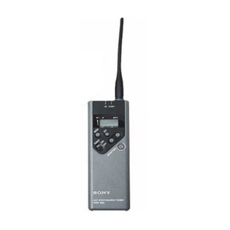
Sony WRR-805A Service Manual
Uhf synthesized portable tuner
Hide thumbs
Also See for WRR-805A:
- Operating instructions manual (94 pages) ,
- Operating instructions manual (20 pages)
Table of Contents
Advertisement
Quick Links
Advertisement
Table of Contents

Related Manuals for Sony WRR-805A


Summary of Contents for Sony WRR-805A
- Page 1 UHF SYNTHESIZED PORTABLE TUNER WRR-805A SERVICE MANUAL CE/AU Model 1st Edition...
- Page 2 Ce manual est destiné uniquement aux personnes compétentes en charge de l’entretien. Afin de réduire les risques de décharge électrique, d’incendie ou de blessure n’effectuer que les réparations indiquées dans le mode d’emploi à moins d’être qualifié pour en effectuer d’autres. Pour toute réparation faire appel à une personne compétente uniquement. WRR-805A...
-
Page 3: Table Of Contents
TABLE OF CONTENTS 1. OPERATING INSTRUCTIONS 1-1. WRR-805A (CE) .................... 1-1 1-2. WRR-805A (AU) ..................1-10 2. SERVICE OVERVIEW 2-1. DISASSEMBLY .................... 2-1 2-2. NOTES ON PARTS REPLACEMENT ............2-2 2-2-1. EEPROM (IC604/MB-861 board) Replacement ........2-2 2-3. ERROR MESSAGES ..................2-2 3. - Page 5 Overview Precautions • Overview ................1 The WRR-805A is a highly reliable portable tuner for the Saved channel setting The unit is designed for use in ambient temperature range 800 MHz band Sony UHF wireless microphone system to The unit stores the channel setting when it is turned off. The of 0°C to 50°C (32°F to 122°F).
- Page 6 No dot: less than 15 dBµ See “Settings” on page 8. contact. If there seems to be poor battery contact, consult your Sony dealer. D GP/CH (group/channel) indication 6 POWER switch Shows the reception channel group and respective channel Turns the power of the tuner ON or OFF.
- Page 7 When connecting the unit to a camcorder, be sure to turn the mode unit off. The time indication accumulates time in hours and minutes when the WRR-805A is on. Display example for CE62 model Connect the OUTPUT (BAL) connector to the microphone Reset the indication to “00:00” whenever you replace the...
- Page 8 Battery life Approx. 6 hours of continuous use 70 dB or more • When using two or more WRR-805As, do not directly put with two Sony LR6 batteries Image rejection ratio one unit upon the other. at 25 °C (77 °F)
- Page 9 Este producto se ha diseñado para proporcionar una Sony = Sony original channel groups / Sony-Kanalgruppen / Grupos de various countries, and will not always guarantee operación excelente sin interferencias en sistemas de canales originales de Sony interference free operation.
- Page 10 12-channel group 8-Kanal-Gruppe 8-Kanal-Gruppe 12-Kanal-Gruppe Sony Original Channel Groups / Sony-Kanalgruppen / Grupos de canales originales de Sony Grupo de 8 canales Grupo de 8 canales Grupo de 12 canales (Channel spacing=125kHz) /(Kanalabstand = 125 kHz) / (Espaciado entre canales = 125 kHz)
- Page 11 Wireless Channel Lists / Übertragungskanallisten / Listas de canales inalámbricos Wireless Channel Lists / Übertragungskanallisten / Listas de canales inalámbricos German User Group-3 / Deutsche Benutzergruppe-3 / Grupo de usuarios alemanes 3 German User Groups / Deutsche Benutzergruppen / Grupos de usuarios alemanes (Kanalabstand (Channel spacing 25kHz) / = 25 kHz) / (Espaciado entre canales = 25 kHz)
- Page 12 Frequenz (MHz) WL-Kanal Frequenz (MHz) Canal WL Frecuencia Canal WL Frecuencia Canal WL Frecuencia Canal WL Frecuencia Sony Original Channel Groups / Sony-Kanalgruppen / Grupos de canales originales de Sony 63-117 808.925 63-151 809.775 63-185 810.625 63-219 811.475 63-118 808.950 63-152 809.800...
- Page 13 Wireless Channel Lists / Übertragungskanallisten / Listas de canales inalámbricos Group 01/Gruppe 01/Grupo 01 UK General Use Groups 10-channel group Gruppen für allgem. Verwendung in Großbritannien 10-Kanal-Gruppe Grupos de uso general para el Reino Unido Grupo de 10 canales (Channel spacing 25kHz) / (Kanalabstand = 25 kHz) / WL Channel Frequency (Espaciado entre canales = 25 kHz)GP/CH indication (example) /...
- Page 14 © 1999 by Sony Corporation [AU66] Overview The WRR-805A is a highly reliable portable tuner for the Remote battery alarm from transmitter 800 MHz band Sony UHF wireless microphone system to be This tuner has capability of receiving “Battery status used for broadcast or movie production purposes.
- Page 15 To maintain this, Sony recommends that one of the original Sony groups, number Output monitoring 11, 12, 13, A1, A2, A3, L1, L2, M1, M2, H1 or H2 is The audio output can be monitored through headphones selected.
- Page 16 Lights when the output audio signal is over the reference left in the holder case and the unit may cause poor battery level. contact. If there seems to be poor battery contact, consult Accumulated time indication Set the battery holder in the original position. your Sony dealer.
- Page 17 The time indication accumulates time in hours and minutes Press the SET button. insert them immediately and repeat the steps on pages 12 when the WRR-805A is on. The tuner enters in group selection mode and the group to 13 from the beginning.
- Page 18 Battery life Approx. 6 hours of continuous use with 70 dB or more • When using two or more WRR-805As, do not directly put two Sony LR6 batteries at 25°C Image rejection ratio one unit upon the other Operating temperature 60 dB or more 0°C to +50°C (32°F to 122°F)
-
Page 19: Service Overview
SECTION 2 SERVICE OVERVIEW 2-1. DISASSEMBLY MB-861 Board/Battery case/Case (Upper) Casa (upper) MB-861 board Battery case 1.7x12 Antenna/RF-93 Board/Case (Lower) 1.7x8 1.7x10 Shield cover Flat cable RF-93 board Antenna Case (lower) WRR-805A (CE, AU) -
Page 20: Notes On Parts Replacement
If the EEPROM (IC604 on the MB-861 board) is replaced, do the following. When the power of the WRR-805A is turned on for the first time after the replacement: 1. “Error 11” appears on the LCD, and data is automatically initialized. -
Page 21: Electrical Alignment
Part No. Remarks MM-SMA Conversion connector J-6402-480-A SMA-BNC Conversion connector J-6402-490-A AF Input/Output Cable Sony K-1334 or equivalent . Wiring diagram 3-pole mini Phone plug (ø 3.5) XLR, 3P connector (male) Chip 1 ; GND 2 ; HOT 3 ; COLD... -
Page 22: Notes On Adjustment
0 dBm = 1 mW at 50 ohm loaded termination probe Signal generator (SSG) 100 dBu Adjust the output of the signal generator (SSG) so that the 50 Z meter reards 50 mV. 50 Z 50 mV WRR-805A (CE, AU) - Page 23 1. Preparation 2. Adjustment Location (1) When adjustments/checking are performed, remove the MONITOR OUTPUT case(upper) and antenna from the WRR-805A unit. RF-93 board RV301 (J302) (J301) (2) Connect between the connector CN1 of MB-861 board and connector CN3 of the RF-93board with harness as...
-
Page 24: Output Level Adjustment
Oscilloscope MM-SMA conversion connector (Part No. J-6402-480-A) TP601 Freqency SMA-BNC conversion connector (Part No.J-6402-490-A) counter AF Input/Output cable (Sony K-1334 or equivalent) Adjuster (0.4 x 1.3 mm) : (Part No. 7-221-652-81) CT601 Connection/Adjustment Location Signal NM - SMA conversion connector... -
Page 25: Muting Level And Rf Level Adjustment
Specification : OUTPUT connector output level connector. (level meter indication level) (2) Turn OFF the WRR-805A POWER switch (S501). = _58.0 dBm ± 0.5 dB (at 600 Z loaded) (3) Set the signal generator as follows : Adjustment : 1 RV301/RF-93 board (A side) -
Page 26: S/N Checking
3-2-4. S/N Checking (5) Turn ON the WRR-805A POWER switch (S501). (6) Release (open) the jumper wire from the TP604 (land) Equipment and Tools Required on the MB-861 board (A side), and check that the DC power supply : +3.00 Vdc ± 0.02 V following indication on the LCD appears as follows : LCD display : “C 1 x x”... - Page 27 RF OUTPUT (output level) : 60 dBuV (10)Set the audio analyzer to the distortion mode. (11)Turn ON the MODULATION of the signal generator. (12)Check that distortion ratio is 0.9 % or less (_41 dB or less) with A-weighted filter. WRR-805A (CE, AU)
-
Page 28: Distortion Ratio Check
CE69 model : Group 00, 6901 channel (854.125 MHz) AU66 model : Group 00, 6601 channel (792.250 MHz) Signal generator setting : FREQUENCY(Carrier frequency) CE62 model : 800.125 MHz CE69 model : 854.125 MHz AU66 model : 792.250 MHz WRR-805A (CE, AU) -
Page 29: Rf Level Indicator Check
RF level indicator Signal generator lights in output level LCD : ± 4 dB 15 dBuV LCD : ± 4 dB 25 dBuV LCD : ± 4 dB 35 dBuV LCD : ± 4 dB 45 dBuV WRR-805A (CE, AU) -
Page 31: Semiconductor Pin Assignments
MA133 MA133-TX —TOP VIEW— CL-165HR/YG-D-T SML-310LTT86 GREEN TRANSISTOR —TOP VIEW— —TOP VIEW— —TOP VIEW— (WIDE) 2SA1965-TL 2SC4738-YGR-TE85L 3SK254-T2 DTA114EE 2SB815B7-TB 2SC4915-O-TE85L (R1=10k,R2=10k) 2SC4919 DTA114EE-TL 2SC4919-TL 2SC5374-TL 2SD2216-Q FMMT617TA —TOP VIEW— —TOP VIEW— DTC114EE XN4504 (R1=10k,R2=10k) XN4504-TX DTC114EE-TL WRR-805A (CE, AU) - Page 32 DET AGC NJM2100V-TE2 (JRC) FM IF DUAL OPERATIONAL AMPLIFIERS FM IF IN DISCRI (DUAL-SUPPLY TYPE) —TOP VIEW— FM DISCRI TUNING METER METER BAND SIGNAL OUTPUT CONTROL BAND SIG AFC/AGC1 AFC/AGC2 REGULATOR FM/AM BAND SELECT RIPPLE FILTER RIPPLE FILTER WRR-805A (CE, AU)
- Page 33 LNA OUT RECTIFIER 3.9k RECT. RECTIFIER 10 pF 3.9k IF BYP RF IN RECT. RECT IF2 OUT RECT MIXER IF1 OUT LO IN COMP. IF BYP COMP. GAIN CELL SUM NODE 2 GAIN CELL GAIN CELL GAIN CELL WRR-805A (CE, AU)
- Page 34 TA75W01FU-TE12R DUAL OPERATIONAL AMPLIFIERS (SINGLE-SUPPLY TYPE) —TOP VIEW— TK11230BMCL (TOKO) REGULATOR USED FOR POWER SUPPLY —TOP VIEW— CONT CONT NOISE BYPASS NOISE BYPASS TA75W393FU (TOSHIBA) TA75W393FU-TE12R THERMAL CONT DUAL COMPARATORS PROTECTION —TOP VIEW— BANDGAP REFERENCE NOISE BYPASS WRR-805A (CE, AU)
-
Page 35: Spare Parts
Therefore, specified parts should be used in the case of replacement. (2) Standardization of Parts Repair parts supplied from Sony Parts Center may not be always identical with the parts which actually in use due to “accommodating the improved parts and/or engineering changes”... -
Page 36: Exploded Views
2-540-507-01 o SHAFT, ROTARY 2-545-712-01 o LABEL (MUTE) 2-545-242-01 o PLATE, LCD 3-678-343-01 s CASE(LCD) 2-545-696-01 s SCREW (S) (M1. 7X8) 3-703-357-08 s PIN (DIA. 1.6 SERISE) 2-545-697-01 s SCREW (M) (M1. 7X10) 3-936-998-01 s SCREW (DIA. 1.7X12), PRECISION WRR-805A (CE, AU) -
Page 37: Electrical Parts List
8-719-069-28 s DIODE 1SS400TE61 C507 1-164-866-11 s CERAMIC 47PF 5% 16V C508 1-162-977-11 s CERAMIC 0.0018uF 10% 50V FB301 1-414-227-11 s INDUCTOR CHIP 0UH C509 1-164-943-11 s CERAMIC 0.01uF 10% 16V FB302 1-414-227-11 s INDUCTOR CHIP 0UH WRR-805A (CE, AU) - Page 38 1-208-927-11 s RESCHIP 47K 0.50% 1/16W R613 1-208-927-11 s RESCHIP 47K 0.50% 1/16W R403 1-208-707-11 s RESCHIP 10K 0.50% 1/16W R614 1-208-675-11 s RESCHIP 470 0.50% 1/16W R404 1-208-687-11 s RESCHIP 1.5K 0.50% 1/16W R615 1-208-675-11 s RESCHIP 470 0.50% 1/16W WRR-805A (CE, AU)
- Page 39 1-164-862-11 s CERAMIC 33PF 5% 16V C210 1-117-739-81 s CERAMIC 3PF 0 16V C211 1-117-735-81 s CERAMIC 2PF 0 16V C212 1-164-862-11 s CERAMIC 33PF 5% 16V C213 1-117-743-81 s CERAMIC 5PF 0 16V C214 1-164-862-11 s CERAMIC 33PF 5% 16V WRR-805A (CE, AU)
- Page 40 1-234-093-21 s FILTER, BAND PASS(for CE62) R222 1-218-849-11 s RESCHIP 3.3K 0.50% 1/16W IC101 8-759-572-44 s IC RF2418TR13 R223 1-218-933-11 s RESCHIP 22 0.50% 1/16W IC102 8-759-355-20 s IC TA31161FN(EL) R224 1-218-941-11 s RESCHIP 100 0.50% 1/16W WRR-805A (CE, AU)
- Page 41 R325 1-208-699-11 s RESCHIP 4.7K 0.50% 1/16W R326 1-208-699-11 s RESCHIP 4.7K 0.50% 1/16W RV301 1-225-668-21 s RES, ADJ, CERMET 4.7K SWF101 1-760-028-11 s FILTER, SAW TH301 1-801-951-21 o THERMISTOR (1005) TH302 1-810-805-21 s THERMISTOR, NTC (1608) WRR-805A (CE, AU)
-
Page 42: Accessories Supplied
5-4. ACCESSORIES SUPPLIED Ref. No. or Q'ty Part No. SP Description 1-790-935-11 s CABLE, CONNECTION 2-545-716-01 s CASE, ATTACHMENT 3-866-674-21 s MANUAL, INSTRUCTION(for CE62,CE69) 3-866-674-31 s MANUAL, INSTRUCTION(for AU66) WRR-805A (CE, AU) -
Page 43: Block Diagram
SECTION 6 BLOCK DIAGRAM CIRCUIT DESCRIPTION MB-861 Board The WRR-805A is composed of the following circuit (1) Output signal control block blocks. There are two signal paths for the audio output signal from the RF-93 board. RF-93 Board One is connected to the main signal path, and the other is (1) RF Block connected to the detector circuit described below. - Page 44 RSSI signal at the learning mode. If “Error11”, that is an indicative of the data error in the EEPROM, is displayed, initial setting shall be carried out again in the learning mode. WRR-805A (CE, AU)
- Page 45 http://getMANUAL.com RF-93 BOARD ANTENNA RF AMP 1st Mixer Filter 2nd Mixer IF AMP IF AMP Discriminator FL101 IC101 FL102 IC101 SWF101 Q101,102 CF101 Q103 CF102 IC102 CF103 CXA1611N J101 2nd LO Buff. AMP CP202 Ceramic Q202 Discriminator (CF104) CP201 140.05 MHz 10.7MHz output Mute...
- Page 47 RF-93 RF-93 SECTION 7 SCEMATIC DIAGRAMS AND BOARD LAYOUTS RF-93 RF-93 -A SIDE- -B SIDE- SUFFIX: -11 SUFFIX: -11 WRR-805A (CE, AU)
- Page 48 MB-861 MB-861 MB-861 -A SIDE- SUFFIX: -11 MB-861 -B SIDE- SUFFIX: -11 WRR-805A (CE, AU)
- Page 49 0 dBu = 1 uV (at no load) 0 dbu = _113 dBm (0 = 1 mW, 50 Z load) 0 dBu = 0.775 Vrms (at no load) For measuring points (A to I), see schematic diagrams. WRR-805A (CE, AU)
- Page 50 The power supply voltage DC 3 V is supplied to the battery spring terminal of the unit. The DC voltages are measured with a digital multimeter (input impedance 1 MZ or more) under no-signal condition. Voltage variations may be noted due to normal production tolerances. RF-93 WRR-805A B-¥APX400-WRR805-RF-93 WRR-805A (CE, AU)
- Page 51 C513 01ZA8.2 C512 DTC114EE 01ZA8.2 0.01 16V B (TPL3) 33 10V MOLD-B (TPL3) CE62 4.7k 5.6k 1.6V Voltage variations may be noted due to normal production tolerances. CE69 5.6k 8.2k 1.8V R507 WRR-805A 47k 1/16W 0.5% B-¥APX400-WRR805-MB861 WRR-805A (CE, AU)
- Page 54 Printed in Japan Sony Corporation WRR-805A (CE, AU) E 1999. 4 11 Broadcasting & Professional Systems Company 9-976-869-01 ©1999...