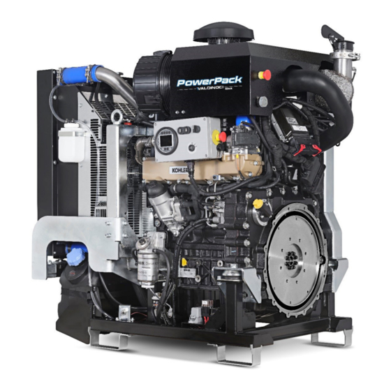
Kohler PowerPack VALDINOCI KDI 3404 TCR Assembly, Use And Maintenance Instructions
Hide thumbs
Also See for PowerPack VALDINOCI KDI 3404 TCR:
- Owner's manual (40 pages) ,
- Owner's manual (40 pages) ,
- Owner's manual (56 pages)
Table of Contents
Advertisement
Available languages
Available languages
Power Pack KDI 3404 TCR
Rev. 1.0 - Settembre/September 2021
IT
ISTRUZIONI DI ASSEMBLAGGIO, USO E MANUTENZIONE
EN
ASSEMBLY, USE AND MAINTENANCE INSTRUCTIONS
Via Antico Acquedotto, 19 • 47122 Forlì • ITALIA • Tel. +39 0543 720 909 •
Istruzioni originali in lingua italiana
Translation of the original instructions in Italian
VALDINOCI LUIGI
S.p.a.
www.valdinoci.it
• motori@valdinoci.it
Advertisement
Chapters
Table of Contents

Related Manuals for Kohler PowerPack VALDINOCI KDI 3404 TCR


Summary of Contents for Kohler PowerPack VALDINOCI KDI 3404 TCR
- Page 1 Power Pack KDI 3404 TCR Rev. 1.0 - Settembre/September 2021 ISTRUZIONI DI ASSEMBLAGGIO, USO E MANUTENZIONE Istruzioni originali in lingua italiana ASSEMBLY, USE AND MAINTENANCE INSTRUCTIONS Translation of the original instructions in Italian VALDINOCI LUIGI S.p.a. Via Antico Acquedotto, 19 • 47122 Forlì • ITALIA • Tel. +39 0543 720 909 • www.valdinoci.it •...
- Page 2 Anno di costruzione / Year of manufacture Matricola / Serial number KOHLER KDI3404TCR s/n 0000000000 Motore / Engine È È C C O O N N F F O O R R M M E E , , I I N N B B A A S S E E A A L L L L ’ ’ A A N N A A L L I I S S I I D D E E I I R R I I S S C C H H I I E E F F F F E E T T T T U U A A T T A A E E S S E E I I N N S S T T A A L L L L A A T T A A...
- Page 3 PER I PAESI CEE • Il gruppo motore endotermico, in base alla Direttiva Europea 2006/42/CE, è da considerarsi una quasi-macchina. • Il Costruttore Valdinoci Luigi S.p.A vieta la messa in servizio della "quasi-macchina" fino a quando la macchina finale in cui deve essere incorporata non è...
-
Page 4: Table Of Contents
INDICE IDENTIFICAZIONE COSTRUTTORE E QUASI-MACCHINA INDICE RIASSUNTIVO OPERAZIONI DI MANUTENZIONE ..............3 Indice riassuntivo operazioni di manutenzione ....3 INFORMAZIONI GENERALI ...........5 Premessa................5 INFORMAZIONI SULLA SICUREZZA ........7 Impieghi ammessi e uso improprio ........7 Avvertenze di sicurezza ............7 Simbologia di redazione ............9 Sicurezza per l'impatto ambientale ........9 Ubicazione dei pittogrammi di sicurezza sul motore ..10 CARATTERISTICHE TECNICHE .........13 Caratteristiche tecniche ............13... -
Page 5: Indice Riassuntivo Operazioni Di Manutenzione
(3) - Testare annualmente le condizioni del refrigerante usando delle apposite strisce per il controllo. (4) - Rivolgersi alle officine autorizzate KOHLER. (5) - Gli intervalli di sostituzione sono puramente indicativi, dipendono fortemente dalle condizioni ambientali e dallo stato dei tubi rilevato durante le regolari ispezioni visive. - Page 6 INDICE RIASSUNTIVO OPERAZIONI DI MANUTENZIONE SOSTITUZIONE DELLA CARTUCCIA DEL FILTRO DELL'OLIO E DELL'OLIO MOTORE FREQUENZA DI INTERVENTO (ORE) VERSIONE MOTORE 1000 2000 5000 KDI TCR Tier 4 final - Stage IIIB - Stage IV - Stage V KDI TCR/D Tier 3 - motore non emissionato SOSTITUZIONE DELLA CARTUCCIA DEL PREFILTRO E DEL FILTRO DEL CARBURANTE FREQUENZA DI INTERVENTO (ORE) VERSIONE MOTORE...
-
Page 7: Informazioni Generali
Valdinoci Luigi S.p.A. Avvertenza • Il presente manuale deve essere consultato unitamente al manuale del motore Kohler installato sulla quasi-macchina. Collegarsi al sito http://iservice.lombardini.it e scaricare sul proprio dispositivo l'ultima revisione disponibile del manuale uso e manutenzione relativa al modello di motore installato nel power pack in Vostro possesso. - Page 8 INFORMAZIONI GENERALI Clausola di Garanzia La Valdinoci Luigi S.p.A garantisce i prodotti di sua fabbricazione da difetti di conformità per un periodo di 24 mesi dalla data di consegna al primo utente finale. Per i motori installati su gruppi stazionari (con impiego a carico costante e/o lentamente variabile entro i limiti di regolazione ) la garanzia è...
-
Page 9: Informazioni Sulla Sicurezza
INFORMAZIONI SULLA SICUREZZA Impieghi ammessi e uso improprio • Chi esegue le operazioni di uso e manutenzione del motore • L’uso previsto del motore è quello in combinazione con la deve impiegare le dotazioni di sicurezza ed i dispositivi di macchina sul quale è... - Page 10 INFORMAZIONI SULLA SICUREZZA • Verificare attentamente il perfetto funzionamento dei • L'avviamento accidentale del motore può provocare gravi dispositivi di sicurezza ogni qual volta si usi la quasi-macchina. lesioni personali o la morte. Prima di qualsiasi intervento su motore o apparecchiatura, scollegare il cavo negativo (-) •...
-
Page 11: Simbologia Di Redazione
INFORMAZIONI SULLA SICUREZZA Simbologia di redazione • Al fine di garantire un utilizzo sicuro, si prega di leggere Qui di seguito sono elencate le avvertenze di sicurezza che si attentamente le seguenti istruzioni. possono trovare all'interno del manuale che indicano di prestare attenzione nell'effettuare particolari procedure potenzialmente •... -
Page 12: Ubicazione Dei Pittogrammi Di Sicurezza Sul Motore
INFORMAZIONI SULLA SICUREZZA Ubicazione dei pittogrammi di sicurezza sul motore Importante Importante • La posizione dei ganci di sollevamento varia tra i diversi • Qualora i segnali di sicurezza risultassero celati da parti della modelli del motore (nel disegno sono rappresentate le versioni struttura della macchina, sarà... - Page 13 INFORMAZIONI SULLA SICUREZZA SEGNALE DESCRIZIONE OCCHIALI DI PROTEZIONE Segnala che è obbligatorio indossare gli occhiali di protezione antinfortunistici prima di effettuare interventi sulla macchina. GUANTI DI PROTEZIONE Segnala che è obbligatorio indossare i guanti di protezione antinfortunistici prima di effettuare interventi sulla macchina.
- Page 14 INFORMAZIONI SULLA SICUREZZA SEGNALE DESCRIZIONE DIVIETO DI RIMOZIONE PROTEZIONI Indica il divieto di rimuovere le protezioni. Attenzione • Sostituire gli adesivi non appena deteriorati. Attenzione • Il mancato rispetto di una qualsiasi prescrizione per deterioramento, perdita o mancata consultazione di un adesivo di sicurezza, può...
-
Page 15: Caratteristiche Tecniche
CARATTERISTICHE TECNICHE Caratteristiche tecniche Modello PowerPack PP 3404 PP 3404 PP 3404 PP 3404 PP 3404 PP 3404 Motore non Tier 4 final Stage V (P<56 Stage 3B Stage IV Tier 4 final emissionato (P<56 kW) Peso Dimensioni (LxPxA) 110x70x123 110x70x123 110x70x123 135,6x74,6x126,6 135,6x74,6x126,6 124,1x74,7x117,8 Normativa... - Page 16 CARATTERISTICHE TECNICHE PowerPack KDI 3404 stage IV / Tier 4 final...
- Page 17 CARATTERISTICHE TECNICHE PowerPack KDI 3404 stage V (P<56 kW)
-
Page 18: Componenti
COMPONENTI Legenda componenti principali... - Page 19 COMPONENTI Pos. Descrizione Filtro aria Radiatore Targhetta PowerPack (posizionata nella parte superiore del radiatore nelle versioni non stage IV - Tier 4 final) Serbatoio urea (presente solo nelle versioni stage IV - Tier 4 final) Fungo emergenza (presente solo nella versione Stage IV - Tier 4 final) Connettore diagnostica Quadro comandi (opzionale) Tappo riempimento olio...
-
Page 20: Prima Dell'avviamento
PRIMA DELL'AVVIAMENTO Movimentazione Movimentazione tramite carrello elevatore Pericolo • Accertarsi che il carrello elevatore sia idoneo al peso del carico da sollevare, pari a: 530kg per le versioni "Motore non Pericolo emissionato", Stage 3B e Tier 4 Final (P<56 kW), 660 kg per le versioni stage IV, Tier 4 Final e stage V. - Page 21 MOVIMENTAZIONE Sollevamento Agganciare il bilancino agli appositi attacchi B prestando Pericolo attenzione che l’angolo delle catene rispetto alla verticale non • Avvalersi di una gru idonea al peso del carico da sollevare, sia superiore a 15°. pari a 530 kg per i Powerpack 3404 "Motore non emissionato", Stage 3B e Tier 4 Final (P<56 kW) e pari a 660 kg per le Nell’immagine 1 è...
-
Page 22: Ancoraggio
ANCORAGGIO Ancoraggio Per il fissaggio del power pack utilizzare gli appositi piedi di appoggio A-B-C-D presenti. Attenzione • Per i modelli KDI 3404 Stage IV/Tier 4 Final sono forniti anche Attenzione gli antivibranti; questi sono adatti a sopportare il peso del motore ed un massimo di 150 kg di accessori montati. -
Page 23: Circuiti
CIRCUITI Batteria Attenzione • La batteria non è fornita; consultare il manuale uso e manutenzione del motore per identificare le batterie consigliate. Collegare negli appositi punti, come indicato nel manuale di installazione del motore, i cavi della batteria: cavo negativo (-) sulla carcassa motore (al di sopra degli antivibranti);... -
Page 24: Collegamento Tubazioni Combustibile
CIRCUITI Collegamento tubazioni combustibile Una volta ancorato il power pack alla macchina, eseguire il collegamento delle tubazioni di aspirazione e ritorno del combustibile. Rimuovere il cappuccio nero di protezione A e montare sul raccordo la tubazione di aspirazione in arrivo dal serbatoio combustibile, fissandola accuratamente tramite una fascetta metallica. -
Page 25: Pannello Comandi
PANNELLO COMANDI Pannello comandi (opzionale) La quasi-macchina può essere dotata di un pannello comandi, rappresentato nella figura sottostante. Ruotare la chiave A su ON per dare tensione e accendere la centralina ATS45 D. Ruotare la chiave A su START per avviare il motore. Ruotare la chiave A su OFF per spegnere il motore. -
Page 26: Manutenzione
MANUTENZIONE Interventi di manutenzione Per reperire le necessarie informazioni sulle tempistiche e sui Pericolo metodi da seguire per eseguire gli interventi di manutenzione ordinaria sul gruppo motore endotermico, consultare: • È estremamente pericoloso commettere errori. Leggere - il paragrafo "Indice riassuntivo operazioni di attentamente il manuale di uso e manutenzione. - Page 27 Non riempire completamente il radiatore, ma lasciare un volume libero adeguato per l’espansione del liquido refrigerante. Avvitare il tappo A del radiatore. 4. Controllo cinghia alternatore (Poly-V) Rivolgersi alle officine autorizzate Kohler. 5. Sostituzione cinghia alternatore (Poly-V) Rivolgersi alle officine autorizzate Kohler.
- Page 28 MANUTENZIONE 6. Sostituzione cartuccia filtro aria Sganciare i due ganci F del coperchio A. Estrarre la cartuccia B. Rimontare: - la nuova cartuccia B; - Il coperchio A verificando la corretta tenuta dei ganci F.
-
Page 29: Rifornimenti
RIFORNIMENTI Rifornimenti 1. Liquido refrigerante Importante • È obbligatorio usare liquido refrigerante anticongelante e protettivo ANTIFREEZE miscelato con acqua decalcificata. Il punto di congelamento della miscela refrigerante varia in funzione della concentrazione del prodotto in acqua. Oltre che abbassare il punto di congelamento il liquido permanente ha anche la caratteristica di innalzare il punto di ebollizione. - Page 30 RIFORNIMENTI 2. Rifornimento ADBLUE (solo per PowerPack Stage IV - Tier 4 final) Svitare il tappo A. Rifornire il serbatoio di AdBlue fino a quando non viene raggiunta la linea rossa dell’oblò B. Importante • AdBlue deve essere conforme alle caratteristiche descritte nel manuale uso e manutenzione del motore.
-
Page 31: Dismissione
DISMISSIONE Dismissione Pericolo • Le operazioni di smontaggio devono essere eseguite esclusivamente da personale specializzato. In caso di dubbi, prima di procedere, contattare il costruttore. Attenzione • Seguire le leggi vigenti nel paese per tutto quello che riguarda: • stoccaggio; •... - Page 32 NOTE ................................................................................................................................................................................................................................................................................................................................................................................................................................................................................................................................................................................................................................................................................................................................................................................................................................................................................................................................................................................................................................................................................................................................................................................................................................................................
- Page 33 TABLE OF CONTENTS MANUFACTURER AND PARTLY COMPLETED MACHINERY IDENTIFICATION SUMMARY OF MAINTENANCE OPERATIONS ....32 Summary of maintenance operations .......32 GENERAL INFORMATION ...........34 Introduction ................34 SAFETY INFORMATION ............36 Intended use and improper use .........36 Safety instructions ..............36 Symbols used in the manual ..........38 Environmental impact ............38 Position of safety signs on the engine ......39 TECHNICAL CHARACTERISTICS ........42...
-
Page 34: Summary Of Maintenance Operations
(2) - The first check must be carried out after 10 hours. (3) - Check coolant effectiveness yearly using the special test strips. (4) - Contact a KOHLER authorised workshop. (5) - Replacement intervals are indicative only as they greatly depend on the environmental conditions and the hose defects found during regular visual inspection. - Page 35 Summary of maintenance operations OIL FILTER CARTRIDGE REPLACEMENT AND ENGINE OIL CHANGE MAINTENANCE SCHEDULE (HOURS) ENGINE VERSION 1000 2000 5000 KDI TCR - Tier 4 final - Stage IIIB - Stage IV - Stage V KDI TCR/D - Tier 3 - non emissionized FUEL PRE-FILTER CARTRIDGE AND FILTER REPLACEMENT MAINTENANCE SCHEDULE (HOURS) ENGINE VERSION...
-
Page 36: General Information
Caution • This manual shall be consulted together with the manual of the Kohler engine installed on the partly completed machinery. Access to the website http://iservice.lombardini.it and download the latest available revision of the owner manual related to the engine model installed on your power pack. - Page 37 GENERAL INFORMATION Warranty Valdinoci Luigi S.p.A Valdinoci Luigi S.p.A warrants its products to be free from defects or non-conformities for a period of 24 months from the date of delivery to the first final user. For engines installed on stationary units (used at constant load and/or slightly variable speed within the setting limits), warranty is granted for a maximum period of 2000 service hours if the 24-month warranty period has not been exceeded.
-
Page 38: Safety Information
SAFETY INFORMATION Intended use and improper use • Personnel using or servicing the engine must use the safety • The engine is intended for use in combination with the machine devices and wear suitable personal protective equipment. on which it is installed. •... - Page 39 SAFETY INFORMATION protective gloves). only be carried out by adequately trained personnel wearing the prescribed personal protective equipment. Fluid injection • During operation the engine surface reaches potentially injuries can have a highly toxic effect and are dangerous. In dangerous temperatures. Avoid any contact, especially with case of injury, immediately seek medical advice.
-
Page 40: Symbols Used In The Manual
SAFETY INFORMATION Symbols used • In order to ensure safe use, carefully read the following Below are the safety notices used in this manual to highlight instructions. precautions or safety information which, if not observed, can result in personal injury or damage to property. •... -
Page 41: Position Of Safety Signs On The Engine
SAFETY INFORMATION Position of safety signs on the engine Important Important • The position of the lifting hooks varies depending on the engine • If the safety signs are hidden by parts of the machine structure, model (the drawing shows the KDI 3404 TCR SCR stage IV they can be moved to a new position, near the original one, - Tier 4 final version). - Page 42 SAFETY INFORMATION SIGN DESCRIPTION SAFETY GLASSES This sign indicates you must wear suitable safety glasses or eye protection before performing any intervention on the machine. PROTECTIVE GLOVES This sign indicates you must wear protective gloves before performing any intervention on the machine. MANDATORY LIFT POINT This sign indicates the anchoring and lift points.
- Page 43 SAFETY INFORMATION SIGN DESCRIPTION DO NOT REMOVE GUARDS This sign indicates that guards must not be removed. Warning • Replace damaged safety signs. Warning • Failure to observe any safety instructions due to a lost or damaged decal/plate or failure to read a safety sign can lead to serious accidents.
-
Page 44: Technical Characteristics
TECHNICAL CHARACTERISTICS Technical characteristics Power Pack model PP 3404 Non PP 3404 PP 3404 PP 3404 PP 3404 PP 3404 emissionized Tier 4 final Stage V (P<56 Stage 3B Stage IV Tier 4 final engine (P<56 kW) Weight Dimensions (LxDxH) 110x70x123 110x70x123 110x70x123 135,6x74,6x126,6 135,6x74,6x126,6 124,1x74,7x117,8... - Page 45 TECHNICAL CHARACTERISTICS Stage IV / Tier 4 final KDI 3404 Power Pack...
- Page 46 TECHNICAL CHARACTERISTICS Stage V KDI 3404 Power Pack (P<56 kW)
-
Page 47: Main Parts
MAIN PARTS List of the main parts... - Page 48 MAIN PARTS Pos. Description Air filter Radiator Power pack plate (affixed to the top of the radiator on non-stage IV - Tier 4 final versions) Urea tank (only for stage IV - Tier 4 final versions) Emergency button (only for stage IV - Tier 4 final versions) Diagnostics connector Control panel (optional) Oil filler plug...
-
Page 49: Before Start-Up
BEFORE START-UP Handling Handling by forklift truck Danger Danger • Make sure the capacity of the forklift truck is suitable for the weight to be lifted, namely 530 kg for Powerpack 3404 • Before handling the partly completed machinery, make sure with "non emissionized”, Stage 3B or Tier 4 Final (P<56 there are no persons within range. - Page 50 HANDLING Lifting Attach the spreader beam to the special lifting points B making Danger sure the chains make an angle of max 15° with respect to the • Use a crane with a suitable capacity for the weight to be vertical.
-
Page 51: Anchoring
ANCHORING Anchoring To secure the Power Pack use the special supporting feet A-B- C-D provided. Warning • For the Stage IV/Tier 4 Final KDI 3404 models, special Warning vibration mounts are also provided. These mounts are suitable to support the weight of the engine plus an additional weight •... -
Page 52: Circuits
CIRCUITS Battery Warning • The battery is not provided. For the recommended batteries, refer to the engine use and maintenance manual. Connect the battery cables to the points indicated in the engine installation manual. Connect the negative cable (-) to the engine housing (above the vibration mounts). -
Page 53: Fuel Line Connection
CIRCUITS Fuel line connection Once the power pack has been anchored to the machinery, proceed with connection of the fuel suction and return hoses. Remove the black protective cap A and connect the suction hose from the fuel tank to the fitting locking it in position with a metal clamp. -
Page 54: Control Panel
CONTROL PANEL Control panel (optional) The partly completed machinery can be equipped with a control panel shown in the following figure. Turn the key A to ON to supply power and turn on the ATS45 control unit D. Turn the key A to START to start the engine. Turn the key A to OFF to stop the engine. -
Page 55: Maintenance
MAINTENANCE Maintenance operations For any information on the routine maintenance intervals and Danger procedures of the endothermic engine unit, please refer to: - section "Summary of maintenance operations” in this • Errors are extremely hazardous. Thoroughly read the use and manual;... - Page 56 Do not completely fill the radiator but leave some room for coolant expansion. Install the radiator cap A. 4. Checking the alternator Poly-V belt Contact a Kohler authorised workshop. 5. Replacing the alternator Poly-V belt Contact a Kohler authorised workshop.
- Page 57 MAINTENANCE 6. Replacing the air filter cartridge Open the two latches F of cover A. Remove cartridge B. Install: - the new cartridge B; and - cover A and close latches F securely.
-
Page 58: Refilling
REFILLING Refilling 1. Coolant mixture Important • Compulsorily use a protective ANTIFREEZE additive diluted with softened water. The freezing point of the coolant mixture varies in relation to the water-antifreeze mixing ratio. The extended life coolant lowers the freezing point, while increasing the boiling point A 50/50 antifreeze and water mixture is therefore recommended to obtain optimum protection and to prevent galvanic corrosion,... - Page 59 REFILLING 2. Filling the ADBLUE tank (only for Power Pack with Stage IV - Tier 4 final engine) Unscrew cap A. Fill the AdBlue tank until reaching the red mark of the sight gauge B. Important • The AdBlue fluid should meet the engine specifications indicated in the relevant use and maintenance manual.
-
Page 60: Dismantling
DISMANTLING Dismantling Danger • Dismantling must only be carried out by qualified personnel. Should you be unsure about anything, contact the manufacturer before starting dismantling. Warning • Observe the local and national legislation in force as regards: • storage; • disposal of materials and fluids used in the partly completed machinery. - Page 61 NOTES ................................................................................................................................................................................................................................................................................................................................................................................................................................................................................................................................................................................................................................................................................................................................................................................................................................................................................................................................................................................................................................................................................................................................................................................................................................................................
- Page 62 NOTES ................................................................................................................................................................................................................................................................................................................................................................................................................................................................................................................................................................................................................................................................................................................................................................................................................................................................................................................................................................................................................................................................................................................................................................................................................................................................
- Page 63 Istruzioni originali in lingua ITALIANA: Questo documento è stato emesso originariamente in lingua Italiana. In presenza di eventuali controversie dovute alle traduzioni il testo di riferimento sarà unicamente la versione italiana. Original instructions in ITALIAN language: This document has been originally issued in Italian. In the event of conflict between the original and translated versions, the Italian version will prevail.
- Page 64 CODICE/CODE REV. DATA/REV. DATE PM01 09/2021 VALDINOCI LUIGI S.p.a. Via Antico Acquedotto, 19 • 47122 Forlì • ITALIA • Tel. +39 0543 720 909 • www.valdinoci.it • motori@valdinoci.it...