Table of Contents
Advertisement
Available languages
Available languages
Quick Links
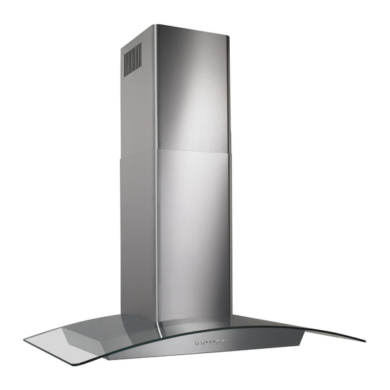
Chimney
Range Hood
READ AND SAVE THESE INSTRUCTIONS
WARNING
TO REDUCE THE RISK OF FIRE, ELECTRIC SHOCK, OR INJURY
TO PERSON(S) OBSERVE THE FOLLOWING:
1. Use this unit only in the manner intended by the manufacturer. If
you have questions, contact the manufacturer at the address or
telephone number listed in the warranty.
2. Before servicing or cleaning unit, switch power off at service panel
and lock service disconnecting means to prevent power from being
switch on accidentally. When the service disconnecting means
cannot be locked, securely fasten a prominent warning device,
such as a tag, to the service panel.
3. Installation work and electrical wiring must be done by qualified
personnel in accordance with all applicable codes and standards,
including fire-rated construction codes and standards.
4. Sufficient air is needed for proper combustion and exhausting
of gases through the flue (chimney) of fuel burning equipment to
prevent back drafting. Follow the heating equipment manufacturer's
guideline and safety standards such as those published by the
National Fire Protection Association (NFPA), and the American
Society for Heating, Refrigeration and Air Conditioning Engineers
(ASHRAE), and the local code authorities.
5. This product may have sharp edges. Be careful to avoid cuts and
abrasions during installation and cleaning.
6. When cutting or drilling into wall or ceiling, do not damage electrical
wiring and other hidden utilities.
7. Ducted fans must always be vented to the outdoors.
8. Use only metal ductwork.
9. Do not use this unit with any other solid-state speed control device.
10. Do not operate any fan with a damaged cord or plug. Discard fan or
return to an authorized service facility for examination and/or repair.
11. GROUNDING INSTRUCTION: The appliance must be grounded.
In the event of an electrical short circuit, grounding reduces the risk
of electric shock by providing an escape wire for the electric current.
The appliance is equipped with a cord having a grounding wire with
a grounding plug. The plug must be plugged into an outlet that is
properly installed and grounded. WARNING: Improper grounding
can result in a risk of electric shock. Consult a qualified electrician
if the grounding instructions are not completely understood, or if
doubt exists as to whether the appliance is properly grounded. Do
not use an extension cord. If the power supply cord is too short,
have a qualified electrician install an outlet near the appliance.
TO REDUCE THE RISK OF A RANGE TOP GREASE FIRE:
a) Never leave surface units unattended at high settings. Boilovers
cause smoking and greasy spillovers that may ignite. Heat oils
slowly on low or medium settings.
b) Always turn hood ON when cooking at high heat or when flambéing
food (i.e. Crêpes Suzette, Cherries Jubilee, Peppercorn Beef
Flambé).
c) Clean ventilating fans frequently. Grease should not be allowed to
accumulate on fan or filters.
d) Use proper pan size. Always use cookware appropriate for the size
of the surface element.
FOR DOMESTIC COOKING ONLY
MODELS EW5630SS • EW5636SS
WARNING
TO REDUCE THE RISK OF INJURY TO PERSON(S) IN THE EVENT
OF A RANGE TOP GREASE FIRE, OBSERVE THE FOLLOWING*:
1. SMOTHER FLAMES with a close-fitting lid, cookie sheet, or metal
tray, then turn off the burner. BE CAREFUL TO PREVENT BURNS.
IF THE FLAMES DO NOT GO OUT IMMEDIATELY, EVACUATE
AND CALL THE FIRE DEPARTMENT.
2. NEVER PICK UP A FLAMING PAN – You may be burned.
3. DO NOT USE WATER, including wet dishcloths or towels – a violent
steam explosion will result.
4. Use an extinguisher ONLY if:
A. You know you have a Class ABC extinguisher, and you
know how to operate it.
B. The fire is small and contained in the area where it started.
C. The fire department is being called.
D. You can fight the fire with your back to an exit.
* Based on "Kitchen Fire Safety Tips" published by NFPA
CAUTION
1. For indoor use only.
2. For general ventilating use only. Do not use to exhaust hazardous
or explosive materials and vapors.
3. To avoid motor bearing damage and noisy and/or unbalanced
impeller, keep drywall spray, construction dust, etc. off power unit.
4. Your hood motor has a thermal overload which will automatically
shut off the motor if it becomes overheated. The motor will restart
when it will cool down. If the motor continues to shut off and
restart, have the hood serviced.
5. The bottom of the hood MUST NOT BE LESS than 24" and
recommended at a maximum of 36" above cooktop for best
capture of cooking impurities.
6. Two installers are recommended because of the size of this
hood.
7. To reduce risk of fire and to properly exhaust air, be sure to duct
air outside. Do not exhaust air into spaces within walls or ceilings
or into attics, crawl spaces, or garages.
8. Be careful when installing the decorative flue and hood, they may
have sharp edges.
9. This hood is not intended to be used as a shelf.
10. Please read specification label on product for further information
and requirements.
Register your product online at: www.broan.com
Installer: Leave this manual
with the homeowner.
Homeowner: Operation and Maintenance
instructions on pages 7 & 8.
Page 1
Advertisement
Table of Contents

Related Manuals for Broan ELITE EW5630SS


Summary of Contents for Broan ELITE EW5630SS
-
Page 1: Range Hood
6. Two installers are recommended because of the size of this hood. 7. To reduce risk of fire and to properly exhaust air, be sure to duct air outside. Do not exhaust air into spaces within walls or ceilings or into attics, crawl spaces, or garages. 8. Be careful when installing the decorative flue and hood, they may have sharp edges. 9. This hood is not intended to be used as a shelf. 10. Please read specification label on product for further information and requirements. Register your product online at: www.broan.com Installer: Leave this manual with the homeowner. Homeowner: Operation and Maintenance instructions on pages 7 & 8. Page 1... -
Page 2: Measure The Installation
MEASURE THE INSTALLATION 6” ROUND DUCT DECORATIVE FLUE 3¾” FROM WALL TO CENTER LINE OF DUCT DECORATIVE FLUE HOOD 3½” 24” 36” ABOVE COOKING SURFACE The minimum hood distance above cooktop MUST NOT BE LESS than 24” . A maximum of 36” above cooktop is recommended for best capture of cooking impurities. -
Page 3: Install The Wiring
INSTALL THE WIRING H O O D C E N T E R L I N E 5 ” M A X . GROUNDING INSTRUCTIONS This appliance must be grounded. In the event of an electrical short circuit, grounding reduces the risk of electric shock by providing an escape wire for the electric current. This appliance is equipped with a cord having a grounding wire with a grounding plug. The plug must be plugged into an outlet that is properly installed and grounded. -
Page 4: Install The Hood
INSTALL THE HOOD (Ducted Hoods Only) Center of Ceiling installation Upper flue mounting bracket slots 1. Center the flue mounting bracket over the hood location and flush with the ceiling. Secure the upper flue bracket to the wall using (2) 4mm x 38mm mounting screws. Note: Drywall anchors may be needed (not included). 2. Tighten the screws completely. Make sure that the bracket is tight against the wall and ceiling. 3. Remove (3) screws holding electronics mounting bracket to hood. Rotate bracket 180 degrees and re-attach bracket to hood with same (3) screws. -
Page 5: Install The Hood
6” ROUND STEEL DUCT DUCT LENGTH DECORATIVE FLUE 10. Measure and install steel ductwork to hood duct connector and ductwork rough-in on ceiling or wall. Use duct tape to make all joints secure and air tight. 11. Plug power cord into wall outlet. 12. Slide the upper decorative flue section into the lower decorative flue section. NOTE For ducted applications, the louvers on the upper flue should be hidden by positioning the louvers down, inside of the lower flue. 13. Carefully place the upper/lower flue assembly into the recessed area of the hood. - Page 6 4. Remove (3) screws holding electronics mounting bracket to hood. Rotate bracket 180 degrees and re-attach bracket to hood with same (3) screws. 5. Remove the grease filter by pulling down the metal latch tab and tilting filter downward to remove. 6. Remove the protective plastic film covering the decorative flue and the hood at this time. 7. Remove the grease filter by pulling down the metal latch tab and tilting filters downward to remove. 8. Align the keyhole slots on the hood with the mounting screws that were partially tightened into the wall framing. Ensure that hood is seated entirely on mounting screws and that hood is level. Then tighten screws completely. MODELS EW5630SS • EW5636SS 9. Install (2) 4mm x 38mm long screws into the holes inside the hood and tighten them securely. 10. Carefully place glass canopy on top of the hood. Align nuts on glass canopy with holes inside the hood. Attach canopy with (4) .188” x .250” long flat head screws. Tighten screws...
-
Page 7: Operation
NON-DUCT PLENUM 6” ROUND FLEXIBLE METAL DUCT DUCT LENGTH DECORATIVE FLUE 14. Measure and install section of flexible metal ductwork (included with RKE56) to hood duct connector and bottom of non-duct plenum. Use duct tape to make all joints secure and air tight. CAUTION Do not use plastic duct. 15. Plug power cord into wall outlet. 16. Slide the upper decorative flue section into the lower decorative flue section. NOTE For non-ducted applications, the upper flue should be oriented so the louvers are towards the ceiling. 17. Carefully place the upper/lower flue assembly into the recessed area of the hood. -
Page 8: Cleaning And Maintenance
To replace a fuse (by qualified person(s): 1. Disconnect power at service entrance. 2. Remove decorative flues. 3. Remove control cover. 4. Remove and inspect fuse. MAKE-UP AIR DAMPER The hood is compatible with Broan Make-Up Air Damper Model MD6T or Model MD8T (optional). Purchase separately. MAKE UP DAMPER CONNECTION MAKE-UP AIR DAMPER (switched low voltage) 20 GAUGE BELL WIRE FOR LOW VOLTAGE CONNECTION ON... -
Page 9: Service Parts
WARRANTY Broan-NuTone warrants to the original consumer purchaser of its products that such products will be free from defects in materials or workmanship for a period of one year from the date of original purchase. THERE ARE NO OTHER WARRANTIES, EXPRESS OR IMPLIED, INCLUDING, BUT NOT LIMITED TO, IMPLIED WARRANTIES OF MERCHANTABILITY OR FITNESS FOR A PARTICULAR PURPOSE. - Page 10 9. Cette hotte n’est pas conçue pour servir d’étagère. 10. Veuillez lire l’étiquette de spécifications du produit pour obtenir plus de renseignements, notamment sur les exigences. Enregistrez votre produit en ligne à : www.broan.com Installateur : Veuillez remettre ce manuel au propriétaire.
-
Page 11: Mesures De L'installation
MESURES DE L’INSTALLATION CAPUCHON DE TOIT CONDUIT ROND CONDUIT DÉCORATIF (3 ¾ ENTRE LE MUR ET LA LIGNE CENTRALE DU CONDUIT CONDUIT DÉCORATIF HOTTE (3,5 À À DESSUS DE LA SURFACE DE CUISSON La distance minimale de la hotte au-dessus de la surface de cuisson NE DOIT PAS ÊTRE INFÉRIEURE à 61 cm (24 po). Un maximum de 91 cm (36 po) est également fortement recommandé pour mieux capter les vapeurs de cuisson. Une distance de plus de 91 cm (36 po) est laissée à la discrétion de l’installateur et des utilisateurs si la hauteur du plafond le permet. INSTALLATION DES CONDUITS (hottes avec conduits seulement) 1. Planifiez la pose du conduit en déterminant son tracé entre la hotte et l’extérieur de la maison. -
Page 12: Installation Du Câblage
INSTALLATION DU CÂBLAGE L I G N E C E N T R A L E D E L A H O T T E M A X . 1 3 C M ( 5 p o ) INSTRUCTIONS DE MISE À LA TERRE Cet appareil doit être correctement mis à la terre. Dans l’éventualité d’un court-circuit, la mise à la terre réduit les risques de décharge électrique en permettant au courant de s’échapper dans un fil. Cet appareil comporte un cordon électrique muni d’un fil et d’une fiche... -
Page 13: Installation De La Hotte
INSTALLATION DE LA HOTTE (hottes avec conduits seulement) Centre de Plafond l’installation Fentes de la bride de montage de conduit décoratif supérieur 1. Centrez la bride de montage du conduit décoratif à l’emplacement de la hotte au ras avec le plafond. Fixez la bride de montage du conduit décoratif supérieur au mur avec deux (2) vis de montage de 4 x 38 mm. Remarque : Des chevilles d’ancrage peuvent être nécessaires (non comprises). 2. Serrez complètement les vis. Assurez-vous que la bride est fermement appuyée contre le mur et le plafond. 3. Enlevez les trois (3) vis qui retiennent la bride de montage électronique à la hotte. Faites pivoter la bride de 180 degrés et fixez-la à nouveau à la hotte avec les trois (3) vis. - Page 14 CONDUIT ROND DE 15 CM (6 PO) LONGUEUR DU CONDUIT CONDUIT DÉCORATIF 10. Mesurez et fixez le conduit en acier sur le raccord de conduit de la hotte et les conduits du plafond ou du mur. Utilisez du ruban pour conduit afin de fixer solidement tous les joints et assurer leur étanchéité. 11. Branchez le cordon électrique dans la prise de courant. 12. Glissez la section supérieure du conduit décoratif dans sa section inférieure. REMARQUE : pour les applications avec conduits, vous devez dissimuler les évents à lames du conduit décoratif supérieur en les faisant glisser à l’intérieur du conduit inférieur. 13. Placez avec précaution les conduits décoratifs inférieur et supérieur dans la partie de la hotte en retrait.
- Page 15 4. Enlevez les trois (3) vis qui retiennent la bride de montage électronique à la hotte. Faites pivoter la bride de 180 degrés et fixez-la à nouveau à la hotte avec les trois (3) vis. 5. Enlevez le filtre à graisse en tirant vers le bas sur la languette métallique de retenue et en basculant le filtre vers le bas. 6. Enlevez la pellicule protectrice en plastique recouvrant la hotte et le conduit décoratif. 7. Enlevez le filtre à graisse en tirant vers le bas sur la languette métallique de retenue et en basculant le filtre vers le bas. 8. Alignez les trous de serrure de la hotte avec les vis de montage que vous avez partiellement serrées dans la charpente murale. Assurez-vous que la hotte est complètement appuyée sur les vis de montage et qu’elle est bien de niveau. Ensuite, serrez complètement les vis.
- Page 16 CAISSON NON CANALISÉ CONDUIT ROND DE MÉTAL LONGUEUR DE 15 CM (6 PO) DU CONDUIT CONDUIT DÉCORATIF 14. Mesurez et fixez le conduit en métal flexible (fourni avec le modèle RKE56) sur le raccord de la hotte et au bas du caisson non canalisé. Utilisez du ruban pour conduit afin de fixer solidement tous les joints et assurer leur étanchéité.
-
Page 17: Nettoyage Et Entretien
Pour remplacer un fusible (le remplacement doit être effectué par une ou des personnes qualifiées) : 1. Coupez le courant au panneau électrique. 2. Enlevez les filtres. 3. Enlevez le couvercle de commandes. 4. Enlevez et inspectez le fusible. CLAPET D’AIR DE COMPENSATION La hotte est compatible avec le Clapet d’air de compensation Broan modèle MD6T ou modèle MD8T (en option). Vendu séparément. CONNEXION DU CLAPET D’AIR CLAPET D’ A IR DE COMPENSATION DE COMPENSATION (basse tension) FIL DE SONNETTE DE CALIBRE... -
Page 18: Pièces De Rechange
Pour le service sous garantie, vous devez (a) aviser Broan-NuTone à l’adresse ou numéro de téléphone mentionnée ci-dessous, (b) donner le numéro de modèle et l’identification de la pièce et (c) décrire la nature de tout défaut dans le produit ou la pièce. Au moment de la demande de service sous garantie, vous devez présenter une preuve de la date d’achat original du produit en question. - Page 19 10. Lea la etiqueta de especificaciones que tiene el producto para ver información y requisitos adicionales. Registre su producto en Internet en: www.broan.com Aviso al instalador: Deje este manual con el dueño de la casa. Aviso al dueño de la casa: Instrucciones de funcionamiento y mantenimiento en la páginas 25 y 26.
-
Page 20: Mida La Instalación
MIDA LA INSTALACIÓN CONDUCTO REDONDO . (15 PULG TUBO DE HUMOS DECORATIVO 3 ¾ . (10 PULG DE LA PARED A LA LÍNEA CENTRAL DEL CONDUCTO TUBO DE HUMOS DECORATIVO CAMPANA 3 ½ PULG . (61 PULG POR ENCIMA DE LA SUPERFICIE DE COCINADO La distancia mínima de la campana sobre la superficie de la estufa NO DEBE SER MENOR de 24 pulg. (61 cm). - Page 21 INSTALE EL CABLEADO L Í N E A C E N T R D E L A C A M P A N A 5 p u l g ( 1 3 c m M Á X . INSTRUCCIONES PARA LA PUESTA A TIERRA Este aparato debe estar conectado a tierra. En caso de un cortocircuito eléctrico, la puesta a tierra reduce el riesgo de una descarga eléctrica al suministrar un cable de escape para la corriente eléctrica. Este aparato está equipado con un cordón que tiene un...
-
Page 22: Instale La Campana
INSTALE LA CAMPANA (sólo en campanas con conductos) Centro de la Cielo raso instalación Ranuras del soporte de montaje del tubo de humos superior 1. Centre el soporte de montaje del tubo de humos sobre la ubicación de la campana y a nivel con el cielo raso. Fije el soporte del tubo de humos superior a la pared utilizando dos (2) tornillos de montaje de 4 x 38 mm. Nota: Podría necesitar anclajes para paneles de yeso (no se incluyen). - Page 23 CONDUCTO REDONDO DE ACERO DE 6 PULG. (15 CM) LONGITUD DEL CONDUCTO TUBO DE HUMOS DECORATIVO 10. Mida e instale los conductos de acero al conector para conductos de la campana y el empalme para conducto sobre el cielo raso o la pared. Use cinta para conductos para fijar y sellar todas las uniones. 11. Conecte el cable eléctrico en el tomacorriente de la pared. 12. Deslice la sección superior del tubo de humos decorativo en la sección inferior. NOTA Para aplicaciones con conductos, el alistonado del tubo de humos superior debe quedar oculto deslizándolo hacia abajo dentro del tubo inferior.
- Page 24 4. Retire tres (3) tornillos que sostienen el soporte de montaje para componentes electrónicos a la campana. Gire 180 grados el soporte y fije nuevamente el soporte a la campana con los mismos tres (3) tornillos. 5. Retire el filtro de grasa estirando hacia abajo la pestaña metálica e inclinando el filtro hacia abajo para quitarlo. 6. En este momento quite la película de plástico protector que cubre el tubo de humos decorativo y la campana. 7. Retire el filtro de grasa estirando hacia abajo la pestaña metálica e inclinando los filtros hacia abajo para quitarlos.
- Page 25 PLENO PARA SISTEMAS SIN CONDUCTOS CONDUCTO METÁLICO FLEXIBLE LONGITUD REDONDO DE DEL CONDUCTO 6 PULG. (15 CM) TUBO DE HUMOS DECORATIVO pestaña metálica del cierre, presione el filtro en su posición y suelte. Asegúrese de que el filtro esté firmemente enganchado después de su instalación. 14. Mida e instale la sección de conducto metálico flexible (incluido con el RKE56) al conector del conducto de la campana y a la parte inferior del pleno sin conducto. Use cinta para conductos para fijar y sellar todas las uniones. PRECAUCIÓN No use conductos de plástico. 15. Conecte el cable eléctrico en el tomacorriente de la pared. 16. Deslice la sección superior del tubo de humos decorativo en la sección inferior. NOTA Para aplicaciones sin conducto, el tubo de humos superior debe quedar orientado de tal manera que el alistonado quede hacia el cielo raso. 17. Coloque con cuidado el conjunto superior/inferior del tubo de humos en el área empotrada de la campana.
-
Page 26: Limpieza Y Mantenimiento
Para reemplazar un fusible (hecho por una persona cualificada): 1. Desconecte la energía en la entrada de servicio. 2. Quite los filtros. 3. Retire la cubierta de control. 4. Quite y revise el fusible. REGULADOR DE AIRE DE REPUESTO La campana es compatible con el regulador de aire de repuesto Broan, Modelo MD6T o Modelo MD8T (opcional). Se compra por separado. REGULADOR DE AIRE CONEXIÓN DEL REGULADOR DE REPUESTO DE REPUESTO (conmutado en bajo voltaje) CABLE DEL TIMBRE CALIBRE 20 PARA CONEXIÓN DE BAJO VOLTAJE EN LA... -
Page 27: Piezas De Servicio
Esta garantía le proporciona derechos legales específicos, y usted puede también tener otros derechos, los cuales varían de estado a estado. Esta garantía reemplaza todas las garantías anteriores. Para calificar en la garantía de servicio, usted debe (a) notificar a Broan-NuTone al domicilio o al número de teléfono que se menciona abajo, (b) dar el número del modelo y la identificación de la pieza, y (c) describir la naturaleza de cualquier defecto en el producto o pieza. - Page 28 MODELS / MODÈLES / MODELOS EW5630SS • EW5636SS Page / Página 28 99527439C...